logo elektroda
logo elektroda
X
logo elektroda

Beginner-Friendly Electronic Circuit Layouts: LEDs, Capacitors & Easy Projects for Students

patricious 131979 45
ADVERTISEMENT
Treść została przetłumaczona polish » english Zobacz oryginalną wersję tematu
  • #1 3226558
    patricious
    Level 12  
    Hello. I'm starting my electronics career :P I am in the 1st year of technical secondary school. But everyone has to start sometime. That is why I am asking for some interesting but simple electronic circuits. It could be anything with LEDs, capacitors, etc., but simple. I don't know where to start, that's why I reach for advice and layouts here. Thanks in advance. Greetings !
  • ADVERTISEMENT
  • #2 3226616
    d.d
    Level 20  
    Hello
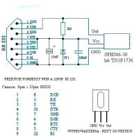
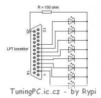
    make yourself led lights for the computer
    eight LEDs
    you connect plus the diodes to pins 2-9
    and the minus you connect and to pin 25

    there are plenty of programs to control
    even on the electrode in the download section there are two
    then you can expand the circuit and instead of diodes, insert npn transistors and connect relays to it
    possibly triacs and without relays
    and you have a home control system :D
    I still have a program to control these devices on lpt via the internet :D

    or do a se girdera
    it is a coma infrared receiver
    you can control the computer with the remote control


    like what, enter exactly what you want to do, you will surely find something
  • #4 3226740
    eP
    Level 27  
    patricious wrote:
    Hello. I'm starting my electronics career :P I am in the 1st year of technical secondary school. But everyone has to start sometime. That is why I am asking for some interesting but simple electronic circuits. It could be anything with LEDs, capacitors, etc., but simple. I don't know where to start, that's why I reach for advice and layouts here. Thanks in advance. greetings !


    Maybe you'd better write what interests you in electronics?

    Do you only want to show off a hand-made gadget or would you like to learn something thanks to it?

    Having access to the network and time to play and learn, you can use it much more effectively than just by having to solder ready-made putties or by mounting simple circuits on universal boards.
    In the past, parts were expensive and finished devices even more expensive. By making some not too complicated layout, you could even save a little on it by spending your time on making one copy.
    Today, parts are relatively cheap and finished products are even cheaper. Such a home tinkering makes sense only because of gaining experience - for economic reasons it is rather completely unprofitable.
    And you can gain experience much faster by getting to know various tools from the electronics workshop. And to handle many of them, you don't need any very advanced knowledge.
    If you are willing and a little patient, you can do much more interesting things in electronics with a computer than with a soldering iron.
    I would recommend you to start with some simulation tool.
    It will cost you much less, but you will learn something useful much faster.

    greetings
  • #5 3227771
    patricious
    Level 12  
    Thanks. Listen to EP, I don't know exactly, you also didn't start with building a TV right away :D I don't know exactly what I would like to do. The only thing I did myself was the LEDs blinking in time with the bass. I'm glad because it's a nice effect. But, for example, I do not know how to connect the 12LED blue ones to 12V? This is where it starts :P greetings.
  • #6 3227984
    eP
    Level 27  
    patricious wrote:
    Thanks. Listen to EP, I don't know exactly, you also didn't start with building a TV right away :D I don't know exactly what I would like to do. The only thing I did myself was the LEDs blinking in time with the bass. I'm glad because it's a nice effect. But, for example, I do not know how to connect the 12LED blue ones to 12V? This is where it starts :P greetings.


    When you are already in a technical school, you should know something that fascinates you about electronics. With online access, you are not at the mercy and disfavor of your teachers alone.
    Even if none of your colleagues is interested in electronics, now it's not a problem for you because you always have the opportunity to find people who know about it in a few moments and will find time to answer your questions.

    It seems to me that you are actually not interested in electronics yet and you just want to be able to boast that you did something there, as long as you do not strain your mind too much :D
    Nobody offers you to assemble TV sets at the beginning, but you are already big enough that it's high time to start using your head not only for games with the computer and friends. :D
  • ADVERTISEMENT
  • #7 3228189
    Anonymous
    Anonymous  
  • #8 3228211
    patricious
    Level 12  
    If you want them to sound quieter, you have to experimentally select a resistor. I have a resistance of 330? for 3 white LEDs, and it must be really loud when it shines, but I love loud music. ;]
    As for the earlier one, does anyone have an idea how to make 12LED under 12V?
  • ADVERTISEMENT
  • #9 3228419
    eP
    Level 27  
    There is a whole separate thread about LEDs in the section about lighting effects.

    But by the way, you could suggest something yourself - if you have no idea about blue LEDs, use the goggles.
  • #10 3229684
    patricious
    Level 12  
    Ok, and could you make me a 1: 1 scale tile pattern for this mixer?
    Because there is a board here, but immediately with elements, i.e. the assembly diagram. It needs the tile pattern itself. Thx
    https://www.elektroda.pl/rtvforum/topic604350.html#3136286 " target="_blank" class="postlink inline" title="" > https://www.elektroda.pl/rtvforum/topic604350.html#3136286
  • #11 4898040
    kunio13
    Level 12  
    Hello!!
    My question is for those who have already made diodes to the rhythm of the bass. Namely, I mean what resistor they used to make the LEDs shine at low volume. Thank you in advance.
  • #12 5204707
    slepy9393
    Level 11  
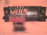
    When it comes to this girder, don't take a risk, I burned the com port: / And this led.jpg project, with each led, the resistor should be separate (when you turn on all the LEDs, it's a bad effect (I apologize in advance for the poor quality of the photo)
    Beginner-Friendly Electronic Circuit Layouts: LEDs, Capacitors & Easy Projects for Students
  • #13 5213432
    Jakub 1551
    Level 13  
    Hey.
    12 LEDs at 12V?
    You connect 4 LEDs in series, and you have 3 rows. You give a resistor to each row and you connect these 3 rows in parallel to the source.
    You figure it out and you will surely get to it. At the beginning you may have too many cables, don't worry, with time they "disappear"
  • #14 5213493
    meek
    Level 15  
    If you want to start playing with electronics, I recommend simple kits, e.g. from Jablo ...
    There you have the tiles and all the elements, plus a detailed description of what to do and how it works. You will make a few putties and you will see what interested you more and you can do some more difficult putties or build something simple on your own ...
  • ADVERTISEMENT
  • #15 5214427
    Anonymous
    Anonymous  
  • #16 5838844
    letho29
    Level 2  
    when it comes to eP development, try to play with PSpice, a really simple and transparent program for building virtual circuits and simulating their operation
    Greetings
  • #17 6154873
    darek_16
    Level 15  
    Hello
    Try to make such a toy
    Beginner-Friendly Electronic Circuit Layouts: LEDs, Capacitors & Easy Projects for Students
    It doesn't have to be 12V at all, I connected a flat 9V battery and it worked too
    I put on a regular diode with increased brightness 3V 5 mm and somehow it holds (it flashed continuously for 30 minutes). The best transistor is bc547 and the capacitor and resistor depend on the length of the blink and the length of the pause
    resistor - break capacitor The length of the diode's flash.
    I put a 10k potentiometer and a 1000 uf capacitor.
    greetings
  • #18 6219321
    piotrb_91
    Level 1  
    Hello everyone!
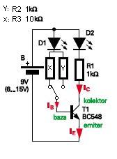
    This is my first post on this forum. I am a beginner. I have a question for the above layout. Will the transistor T1 conduct if no current flows through the base? I don't think so, but please reply.
  • #19 6300227
    bejano
    Level 1  
    When no current flows through the base, no current should actually flow through the transistor, unless the voltage is so high that a breakdown occurs. The operation of this system is precisely based on the breakdown.
    At first, nothing happens because the capacitor is charging. Then the voltage across the transistor increases to 12V minus the voltage drop across the potentiometer. The potentiometer should be set so that the voltage across the transistor slightly exceeds its breakdown voltage. Then current will flow through the transistor and the diode will glow. At this point, the capacitor starts to discharge and the voltage drops across the transistor. The transistor (if it is not damaged) stops conducting again and the diode turns off. The whole process starts all over again, i.e. the capacitor is charging etc ...
    With the appropriate potentiometer setting, the diode should blink. If it is still on, either the potentiometer has too low resistance or the transistor has been damaged
  • #20 6300588
    Morfeusz1991
    Level 15  
    You can add http://www.belza.cz/hf/bug.htm to the collection of easy things
    I will add that this radio does not require a plate, i.e. you can solder everything "in the air"
  • #21 6408527
    Alann7
    Level 11  
    Hello!

    This is my first post.

    In my technique exercise class there is the following task:

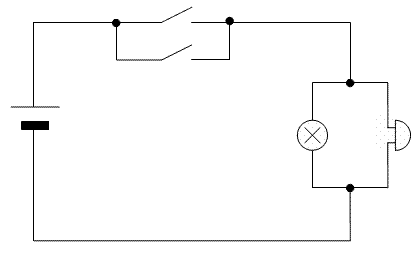
    "Make a project and draw a diagram of the alarm system, e.g. securing the car against theft. The system is to consist of:

    -battery
    - bulbs
    - the ringtone
    -two switches

    The installation is to meet the following conditions:

    - with each switch we can turn on the bell and the light bulb at the same time.

    - unscrewing the bulb does not affect the bell operation and vice versa. "

    I drew such a diagram, but I would like to ask you if it is well drawn :)

    https://obrazki.elektroda.pl/19_1239613093.jpg


    I am waiting for a response :)
  • #22 6412340
    pawem1
    Level 25  
    Bad, because the first condition is not met, the circuit breakers should be together in parallel.
  • #24 6412832
    Alann7
    Level 11  
    Thanks :) And did the bulb and bell do well? (I forgot to give these connections only).
  • #25 6467554
    adriansuru
    Level 1  
    Hello, I have a question - can someone explain to me what it is:
    R1 *
    T1
    C1
    D1
    i bought all the parts but i don't know how to put it together.
  • #26 6470209
    Alann7
    Level 11  
    These are the markings in the diagram, eg R1 will be a resistor, T1 - transistor, D1 is a diode. It can also be R2, R3 because these numbers only number them to make it easier. You can connect everything on a universal board. :)
  • #30 6709692
    maras3103
    Level 9  
    Hello, I'm new to this forum from September, I'm going to the electronic technical school and I would like you to help me how to connect such a system as the one below, only with, for example: 4 LEDs. Please give me a diagram and a list of elements, thank you in advance. Regards


    darek_16 wrote:
    Hello
    Try to make such a toy
    Beginner-Friendly Electronic Circuit Layouts: LEDs, Capacitors & Easy Projects for Students
    It doesn't have to be 12v at all, I connected a flat 9v battery and it worked too
    I put the ordinary diode with increased brightness 3 v 5 mm and somehow it stays (it flashed continuously for 30 minutes). The transistor is best bc547 and the capacitor and resistor depend on the length of the blink and the length of the pause
    resistor - break capacitor The length of the diode's flash.
    I put a 10k potentiometer and a 1000 uf capacitor.
    greetings

Topic summary

The discussion revolves around beginner-friendly electronic circuit layouts involving LEDs and capacitors, aimed at students starting their electronics journey. Participants suggest various simple projects, such as LED flashers and LED lights for computers, and provide guidance on connecting components like resistors and transistors. Key advice includes using series and parallel configurations for LEDs, experimenting with resistor values to control brightness, and utilizing simulation software for circuit design. The conversation emphasizes the importance of hands-on experience and learning through practical projects, while also addressing common issues faced by beginners, such as component connections and circuit functionality.
Summary generated by the language model.
ADVERTISEMENT