 Hello my dears
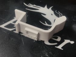
I would like to introduce you to my mini-tutorial of the free Blender program. The tutorial will focus on showing that although Blender is more artistically inclined, it is also suitable for preparing a simple 3D printable element. I will map the 3D element from a photograph - so that it is compatible with the original. The part I will reproduce will be a lamp shade holder (with a clip and a screw hole).
I'm going to use the popular version of Blender 2.79 for the theme, as I consider it to be stable and it seems to be the version with the most material (and plugins) at the moment.

Of course, it doesn't matter that much, as the model creation mechanisms in other versions of Blender are almost identical.
I will print the piece on a Creality Ender 3 Pro 3D printer with PLA filament.
Introduction
The tutorial will be divided into two sections.
In the first section, I will loosely present a set of useful information and keyboard shortcuts that can come in handy no matter what you are doing. I recommend testing them all on an empty Blender scene.
In the second section, I'll describe step-by-step how I 3D mapped the object from the photo (the lampshade mount) so that I could then 3D print it and replace the print with a component that simply broke.
Of course, I will inevitably not be able to include all the information here, so if something is missing you can always look for the answer in the Blender documentation or in the Blender forum and/or stack exchange.
Basic information, operations and keyboard shortcuts
I will describe here some general concepts from Blender that you should know before proceeding.
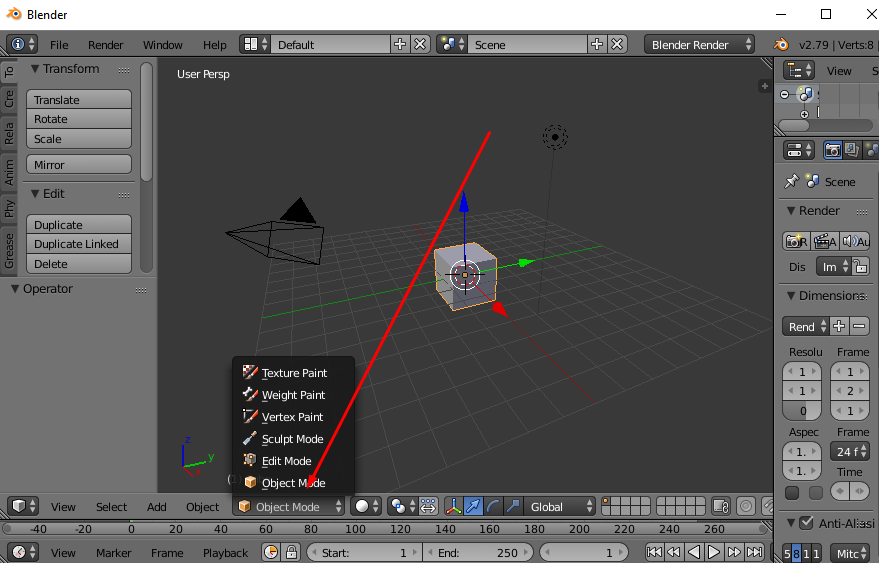
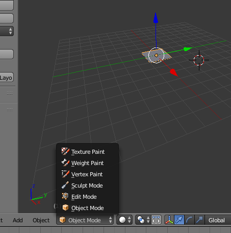
- there are two levels of editing in Blender: Object Mode (move/scale/rotate etc whole shapes, solids) and Edit Mode (edit vertices, faces, edges of one solid). Switch between them with the TAB key. You can also switch between them on the GUI:
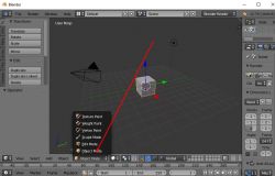
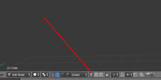
- in Edit Mode there are three selection/editing sub-modes, namely operations on vertices, edges and faces. These are selected here:
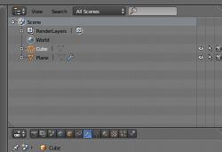
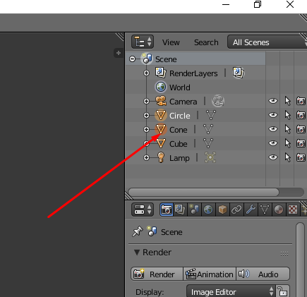
- objects are selected with the right mouse button. PPM alone changes the selection to the clicked object. If you want to select two objects, you click PPM on the object while holding Shift. The clicked object is then additionally selected (the previous object is also selected). In addition, we have the keyboard shortcut A (from 'All'), which means selecting (or deselecting) everything in the scene. The list of objects in the scene is in the upper right corner (where you can also see what you have selected):

- you can also select objects in bulk by holding C and LMB and moving the cursor over the objects you want to select (drag selection)
- you can also select with the B key, the so-called 'box select'
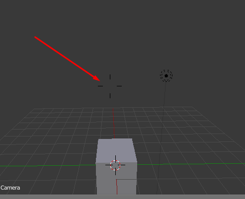
- it is best to move the camera in flight mode, SHIFT + F. Then fly with WSAD and accept the camera settings with LPM. If you do not wish to change the camera settings, you can undo them using Escape. In camera move mode (SHIFT+F) a cursor/target like this appears on the screen:

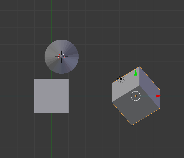
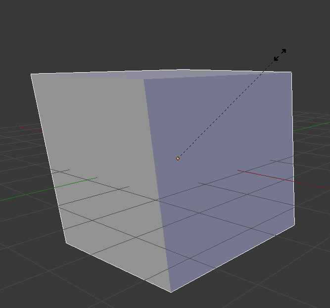
- there are also convenient keyboard shortcuts for operating the camera. The numeric '5' key toggles between perspective mode:
and ortho mode:
In addition, we can automatically set projections from the front/right/etc. etc. with the numeric keys 7 9 1 3. Keys 8,4,6,2 (numeric arrows) rotate the camera.
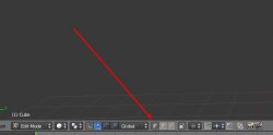
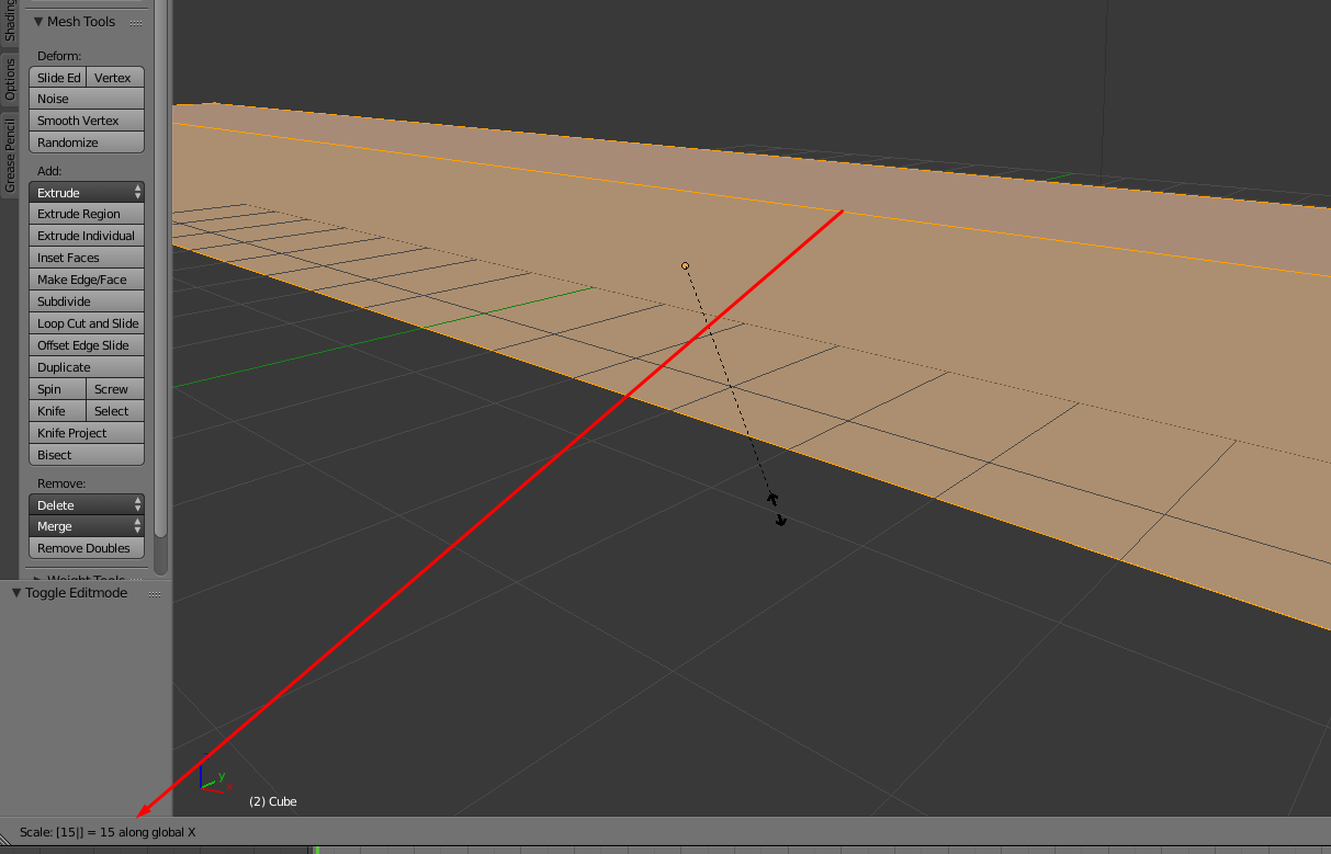
- in Blender we can move, rotate and scale what we have selected. This uses the keyboard shortcuts G (grab; move), S (scale; scale), R (rotation; rotate). By pressing the corresponding key, you can specify whether you are scaling/moving along one axis (to do this, press X or Y or Z) or all axes (default option). Each of these transformations can be performed by a numerical value by typing an offset from the keyboard, for example. For example, if we want to move the selection by 50 units along the X axis we press: G (enables shifting), X (selects the X axis), 50 (i.e. 5 and 0 from the keyboard) and confirm with LPM.

When we perform operations according to an axis by a value from the keyboard, we have a preview of what we have typed in the bar at the bottom:
 Modeled component - replacement shade holder for 12V decorative light
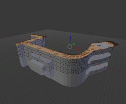
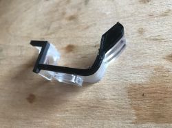
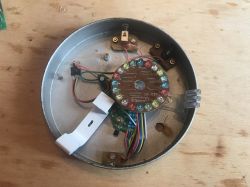
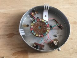
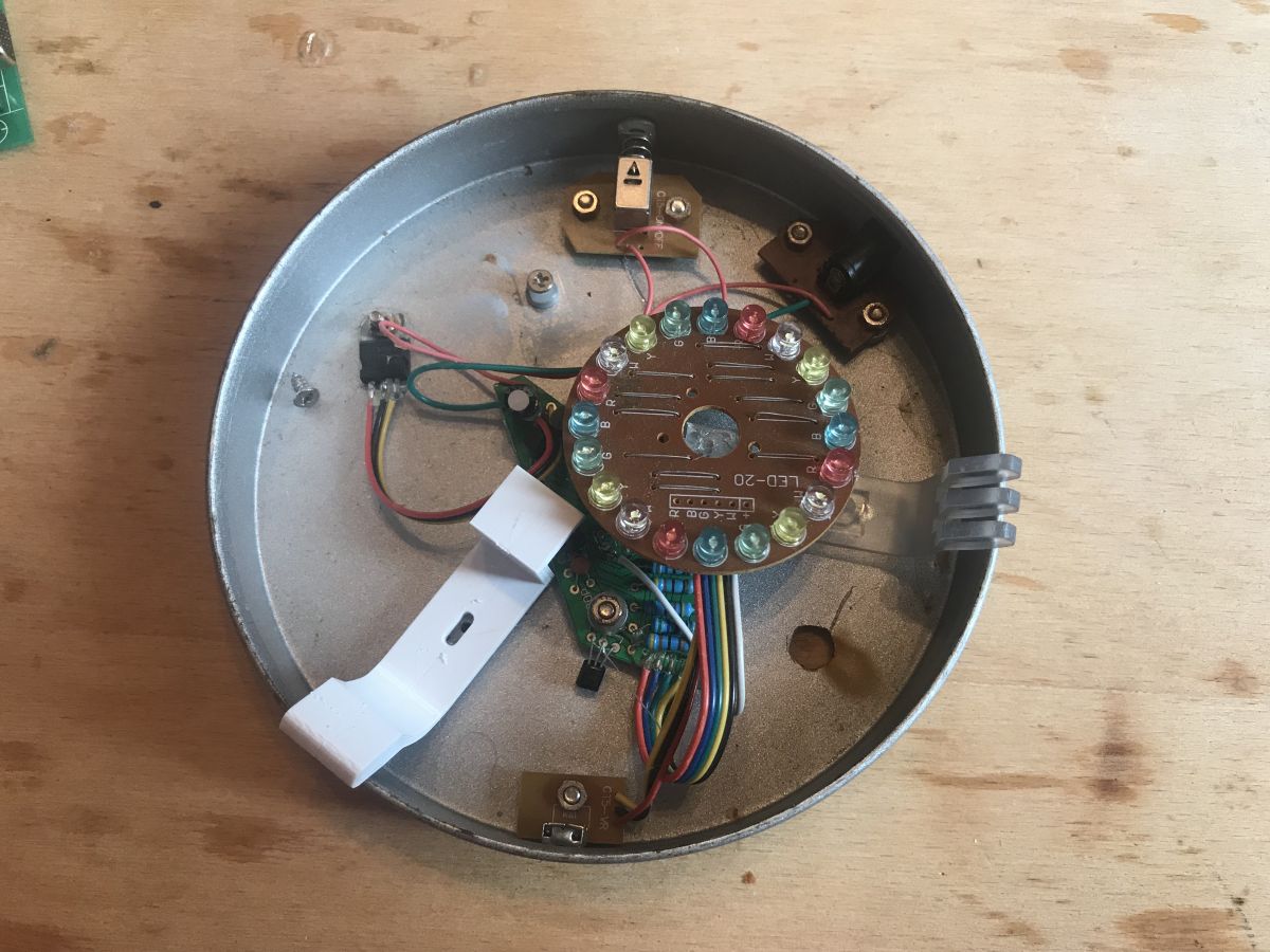
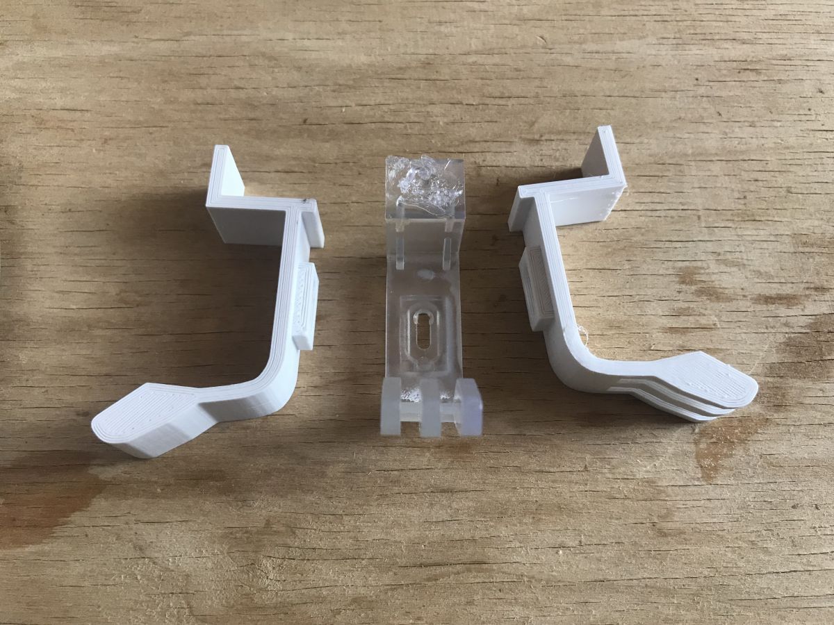
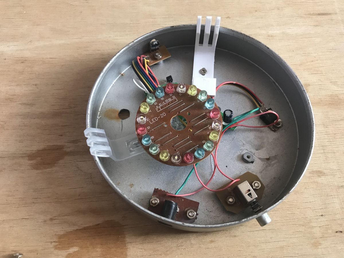
In this tutorial, I'll show how to model a replacement for the diffuser mount from a 12V ornamental lamp under 3D printing. The original mount was probably some kind of factory flimsy, as it broke shortly after purchase. The base from the lamp looks like this:
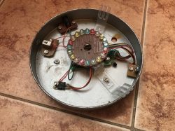
In the photo you can see the two brackets made of transparent plastic. The lampshade overlaps them, they are quite springy, but this is not a problem, as PLA filament prints also have their springiness and are not breakable.
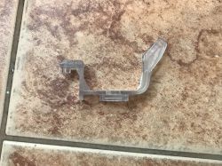
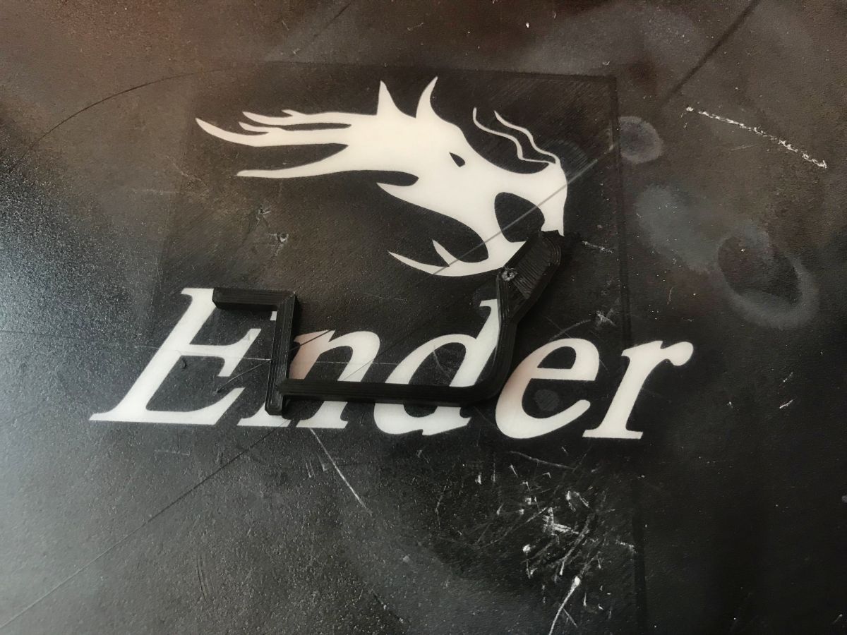
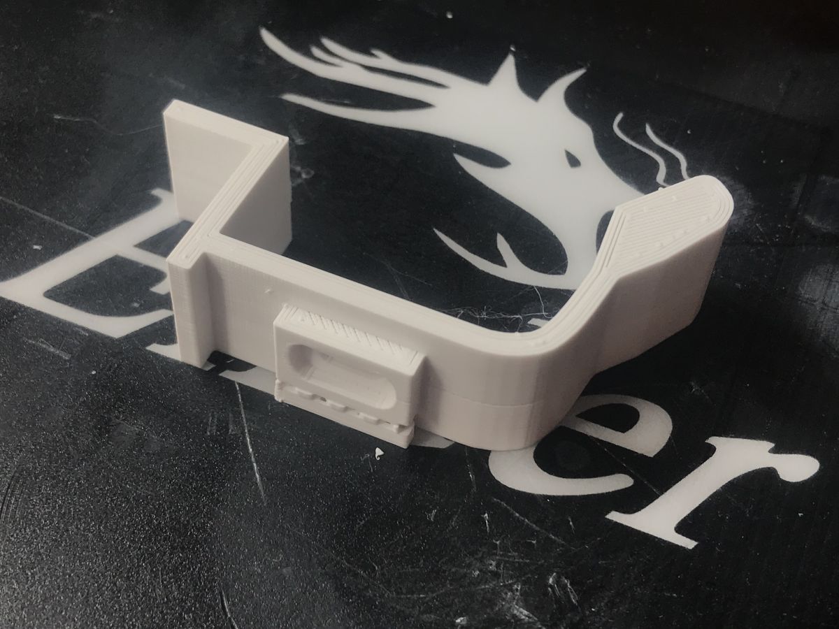
The attachment piece after removal:
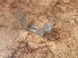
Before modelling it, it is a good idea to take a photo of it from above - we will use it as a background when mapping its outline. This will keep the proportions correct (and the scale can be chosen later).
If we have a regular scanner, we can simply scan the element instead of the photo - then we will get a better outline of it for the background, because we will avoid the problem of perspective distorting the proportions a bit.
So much for the introduction, we are about to move on to modelling.
Step 1: Prepare an empty scene
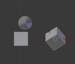
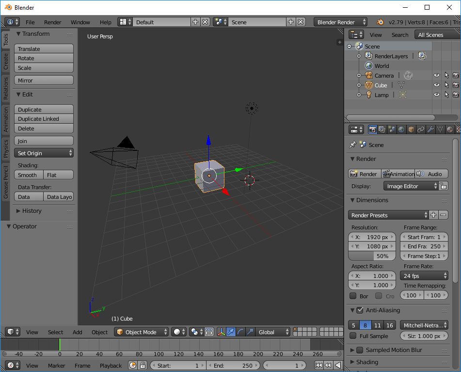
When we start Blender we will be presented with the default scene, which is a single Cube, light and camera in an empty space:
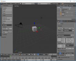
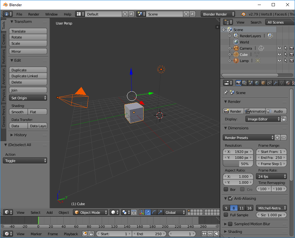
We won't need it, so we press 'A' to select everything:
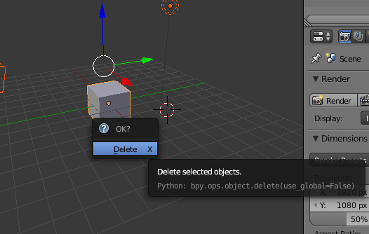
And then Delete to remove the selection:

In this way we gain an empty scene.
Step 2: We add the object
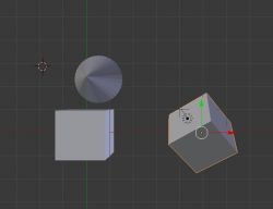
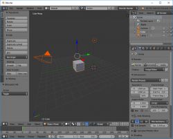
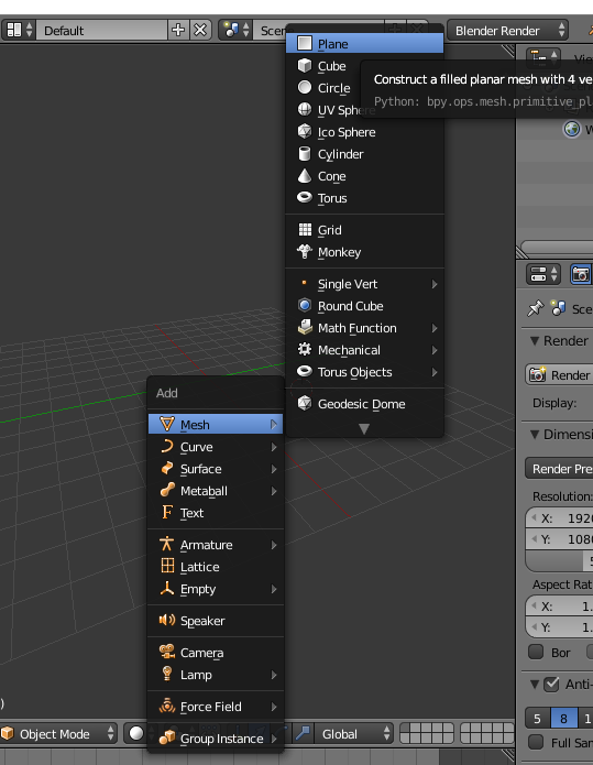
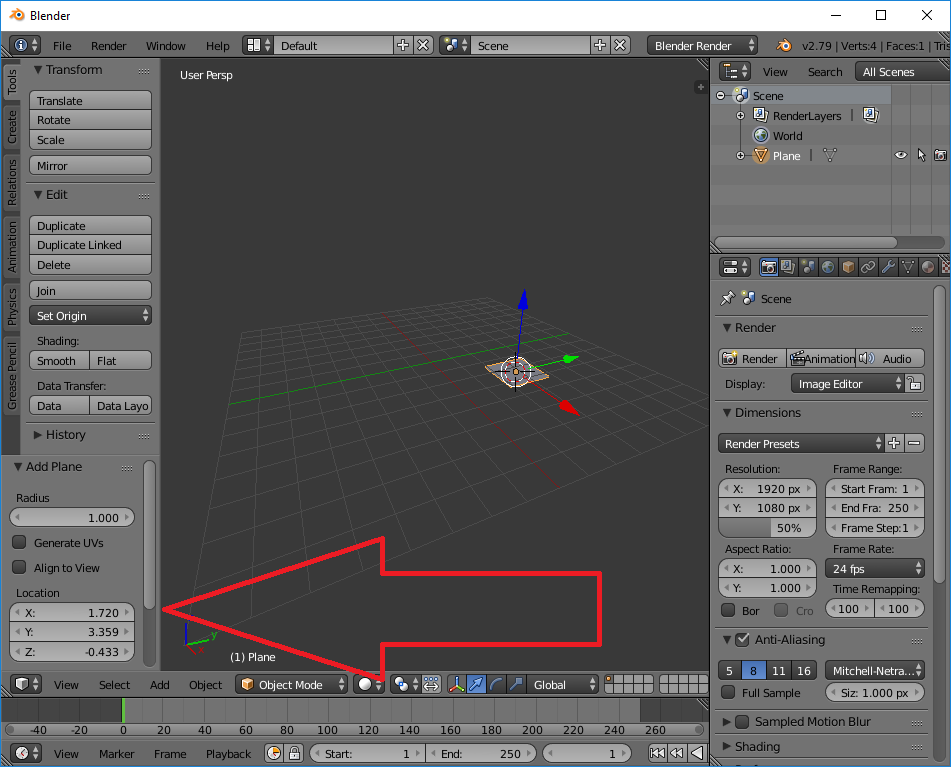
I will start modelling the object with a simple object consisting of four vertices. We add it by pressing SHIFT+A and selecting Plane from the list:

It is then worth setting its position to 0,0,0 in the add options (highlighted in the image):

This way we get a plane at the centre of the coordinate system.
Step 3: Edit Mode
At this stage we can change the editing mode from Object Mode (operating on whole objects, moving them, etc.) to Edit Mode (operating on the shape of objects, their vertices, triangles, etc.). This can be done with the mouse or with the TAB key. The current edit mode is here in the drop-down list:
 Step 4: Moving the camera
The camera on the stage can be moved in the following ways:
- by using the mouse wheel to simply zoom in/out
- if you press Shift+F you can fly the camera with the WSAD keys and rotate the mouse view
- number key 5 toggles between ortho and perspective modes
- number keys 1, 3, 7, 9 conveniently switch between side/hill/etc. projections
When working, position the camera so that you are comfortable, and always check several times that what you are modelling looks as it should from all sides. A popular mistake among beginners is to look at your model from one projection all the time and unconsciously create it with various strange offsets that cannot be seen from one camera, for example.
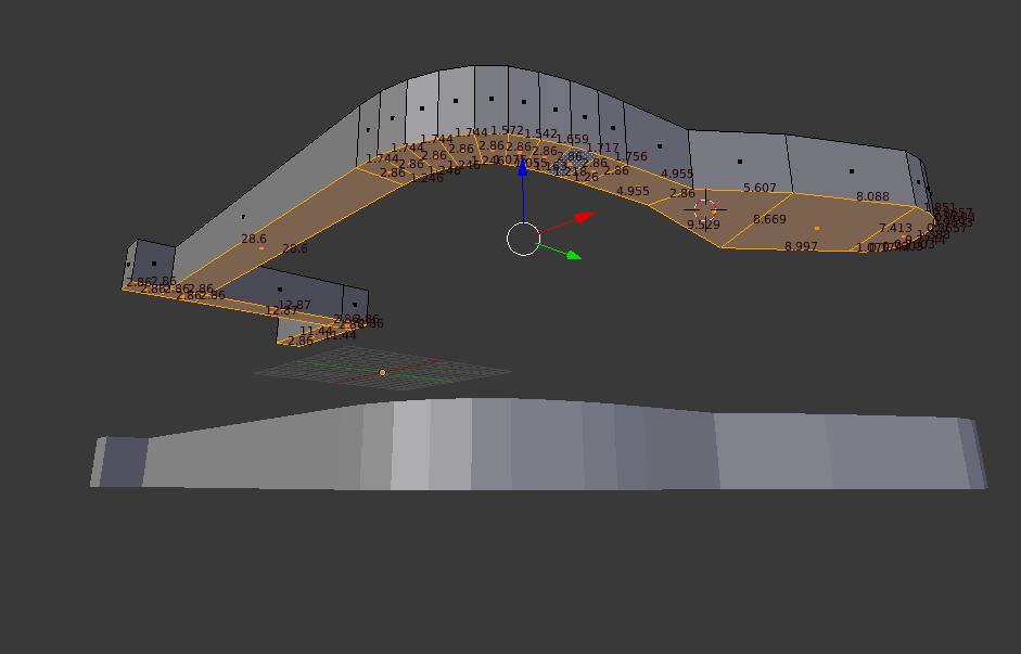
Step 5: Displaying dimensions
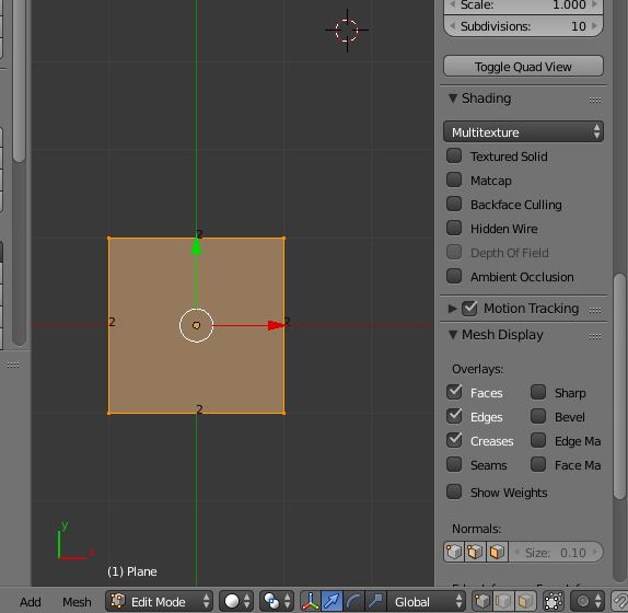
At the beginning, it is also a good idea to enable the display of dimensions. This option can be found in the side menu toggled with the N button:
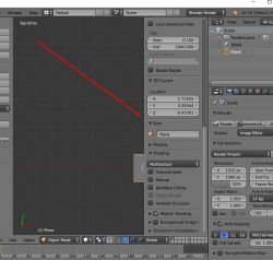
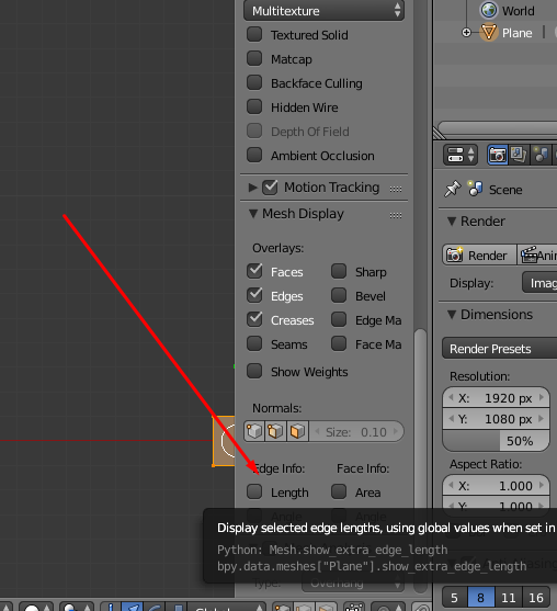
This option is called 'Edge Info/Length', it is available when we are in Edit Mode. It is located in 'Mesh Display':
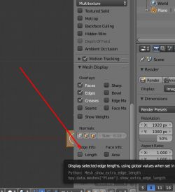
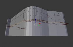
Turning it on results in Blender showing the edge length (in Edit Mode, for the shape being edited at the moment):

Right next to 'Length' there are other display options, such as Angle, but these are not as useful as Lenght in my opinion.
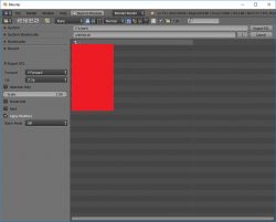
Step 6: Background image
A very useful feature is the ability to set a background image. This makes modelling much easier and allows us to represent an object in detail.
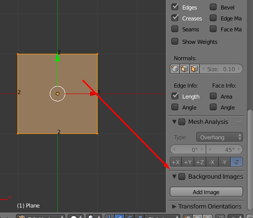
The 'Background Image' option can be found a little further down in the menu accessible under the N key:
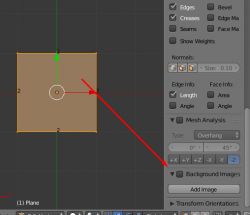
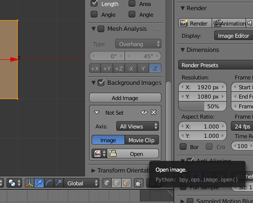
To activate it, we need to tick the checkbox next to 'Background Image' and then click 'Add Image'.
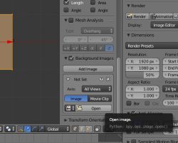
We can then select the background image using 'Open':
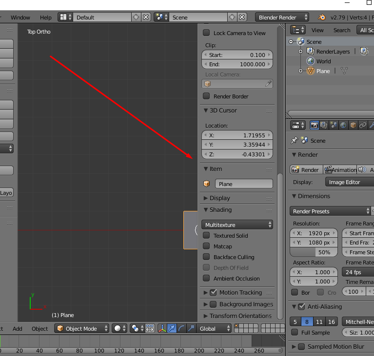
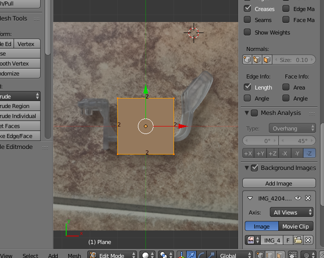
Once the image is selected, the background will appear immediately, but only in the top/right/itp ortho projection view:
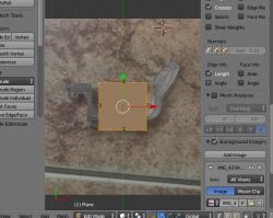
In the perspective camera view the background does not display. This is normal. So if your background is not displaying, check what view you have set (numeric key 5 toggles perspective/ortho).
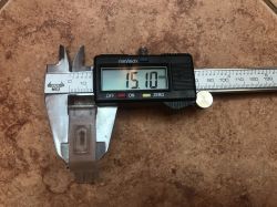
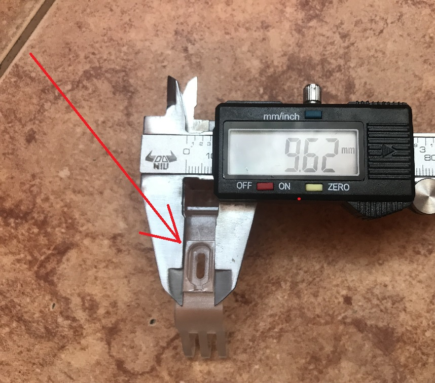
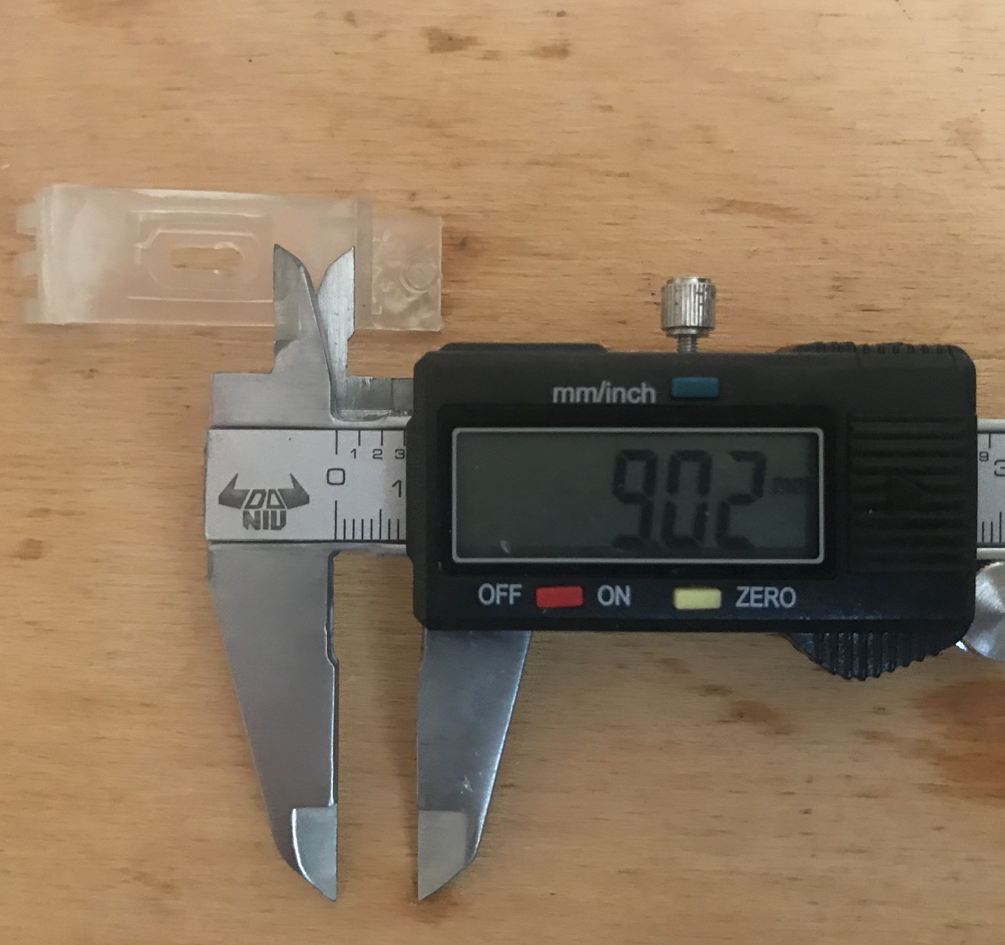
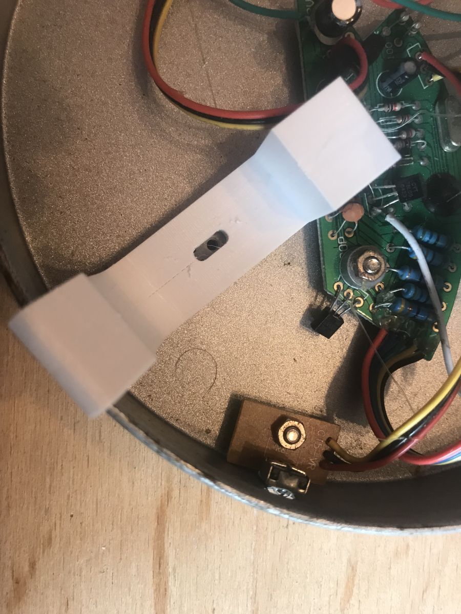
Step 7: Scaling the background
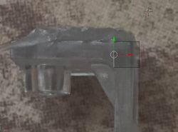
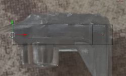
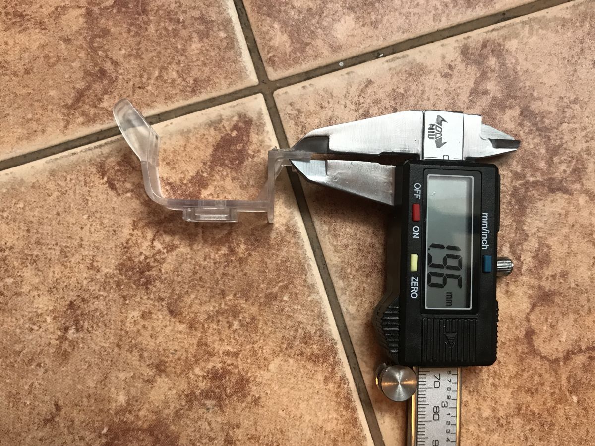
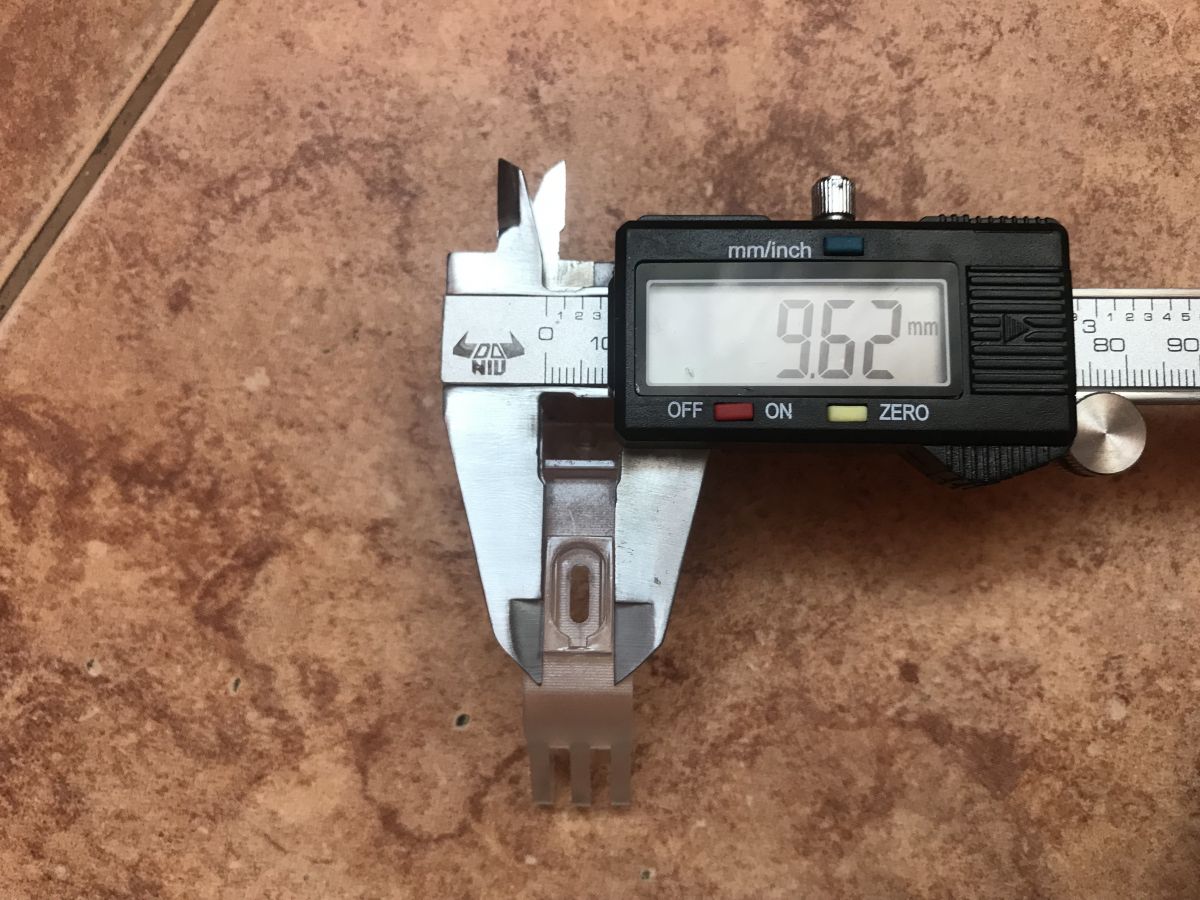
At this stage it is a good idea to scale the background so that it matches the actual dimensions of the object. To do this I measured the thickness of the section of the object I was modelling:

I assumed that there were 2mm there.
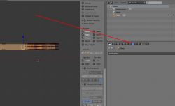
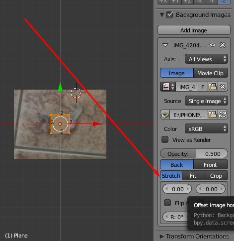
I then matched the background photo to the scene object so that the dimensions matched, the background photo can be moved and scaled here:
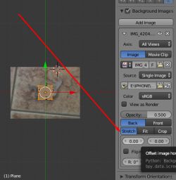
By the way, it is also worth pressing Z to make the triangles of the edited object transparent.
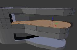
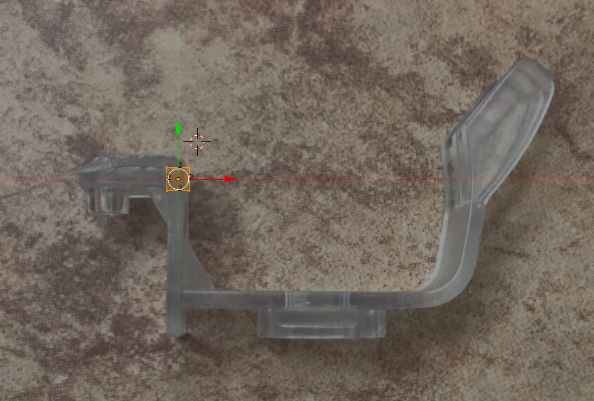
After scaling and centring:
 Step 8: Modelling the outline of the shape in 2D
Now we can map the shape of the object from the photo.
This can be done in various ways, I will only present one of them.
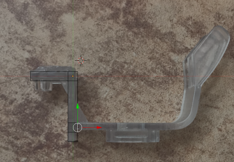
To do this, we select the edge mode, here:
Then select one of the edges of the object (right click on the edge):
Then press E to perform an Extrude operation (create additional edges/surfaces from the one selected) and, holding CTRL (respecting the grid), pull the newly created geometry to the side:
We repeat the same for the rest of the outline (except for the rounded corner, if necessary).

It is also worth mentioning that the keyboard shortcut G allows you to simply move the selection and then CTRL (grid) also works.
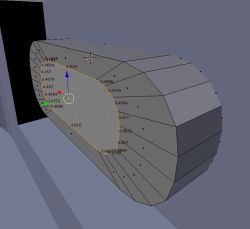
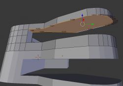
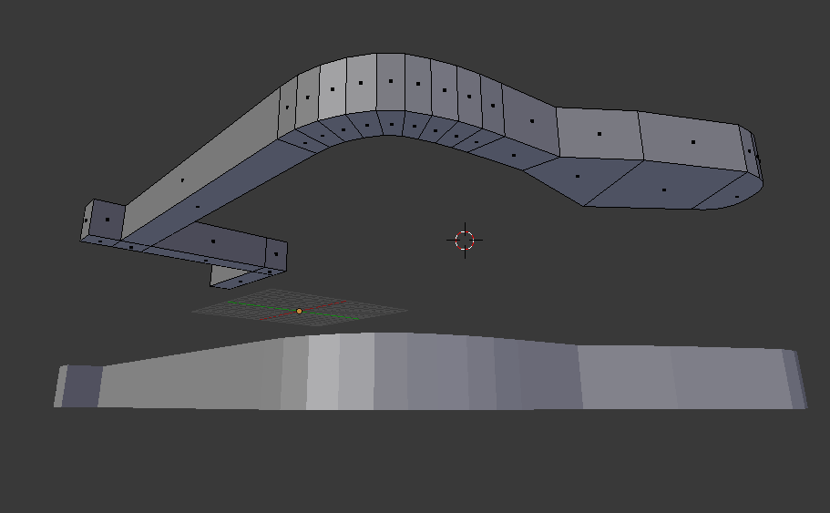
Step 9: Continue Extrude outline, rounded corner (Spin tool)
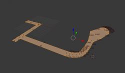
The finished outline came out like this for me:
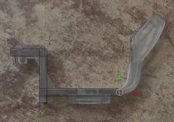
Now you need to add the rounded section.
This can be done manually, but more cleverly you can use Blender's ready-made functionality, Spin.
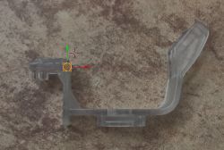
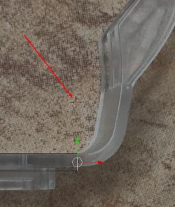
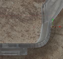
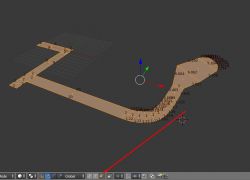
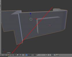
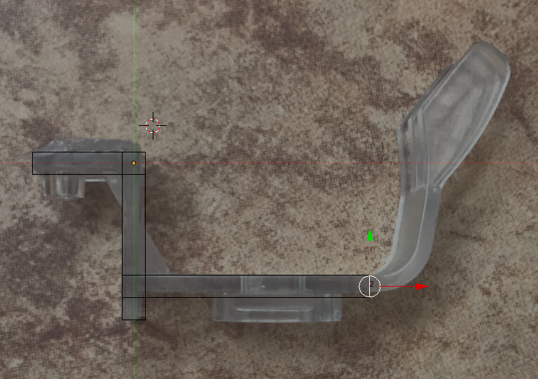
Spin works by doing an Extrude operation repeatedly, rounding the current selection around the position of the 3D cursor.
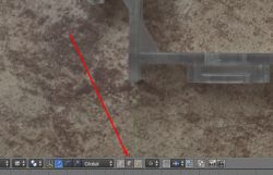
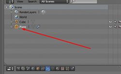
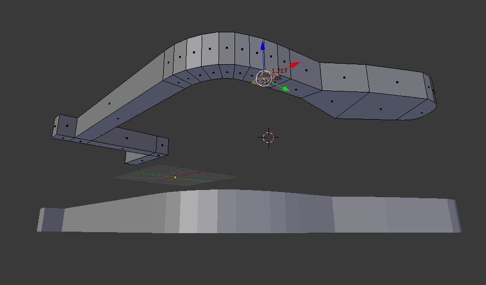
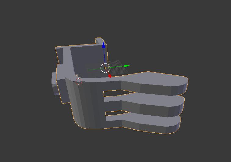
The 3D cursor is positioned at the centre of the radius simply by clicking LMB (the arrow in the screenshot shows the 3D cursor):
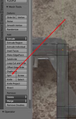
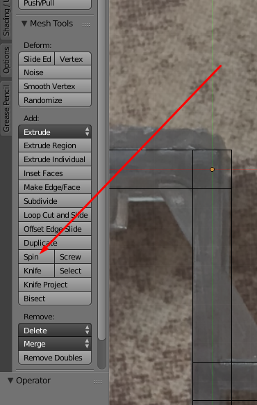
Then from the menu on the left (toggled with the T button) select Spin options:
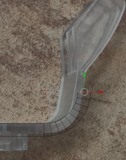
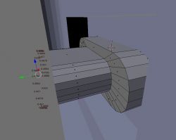
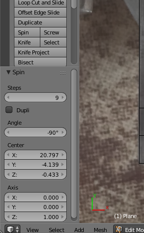
For Spin, the angle can be selected (a negative angle results in rotation in the other direction):
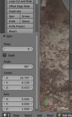
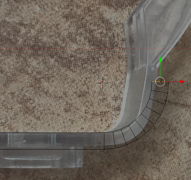
In my case, the spin resulted in the creation of such geometry:
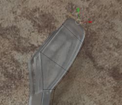
Of course it won't come out perfectly the first time, we can go back and correct the cursor position and spin parameters many times.
Final version:
 Step 10: Rest of outline, corrections
We create the rest of the outline in the same way. We can also assist by moving edges or vertices (select edit vertex mode and move them one at a time).
 Step 11: Round the corner using Bevel
The end of the modelled object is rounded. This can be done manually, or with the help of the Bevel tool, which creates roundings for selected angles (vertices).
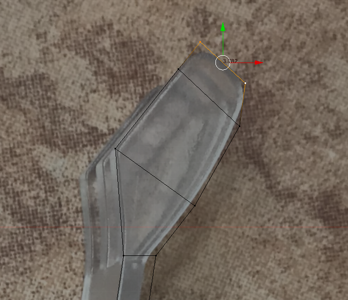
Before using it, the object looks like this:
In the screenshot, I already have the vertices to be rounded selected.
Bevel for the vertices is switched on with the shortcut SHIFT + CTRL + B (for the edges CTRL + B is enough, I recommend experimenting with this)
We control the degree of rounding with the mouse, the density of the new vertices created with the mouse wheel.
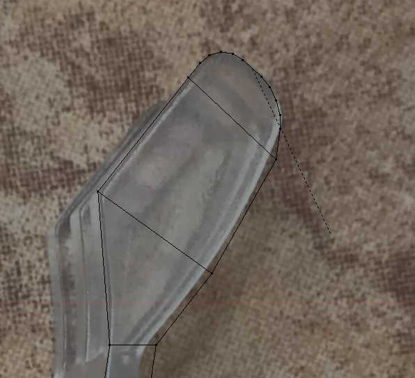
The result:

In this way, we can quickly round off sharp edges.
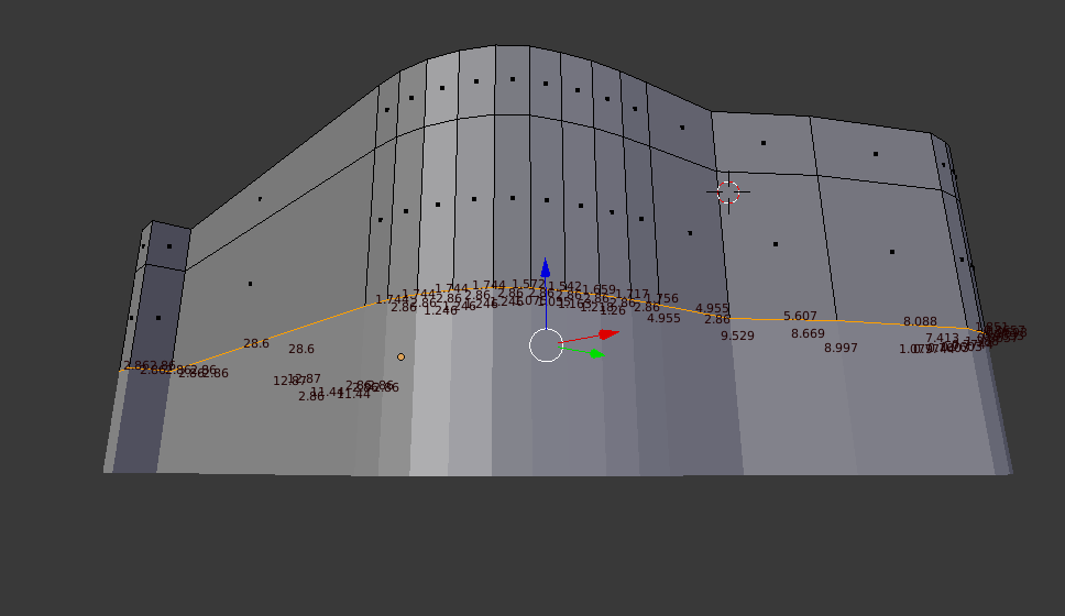
Step 12: Welcome the third dimension, we give the object a thickness
The outline is fully complete. We can now turn on the perspective view and view our final result. It is also a good idea to disable the transparency option (Z key) for this purpose:
It is useful to know how thick the finished object should be:

To give thickness we will use the Extrude option already mentioned, but in faces (walls) mode:
We select everything and press E, and then we can type from the keyboard how much we want to extrude upwards on the object. I chose 2.5mm (I typed 2.5). The result:
 Step 13: Break - test print, scale corrections
At this stage it is a good idea to make a 'test' printout to check that we have definitely reproduced all dimensions with sufficient accuracy.
A test print, that is, we just normally print out what we now have modelled - just to compare the live dimensions to see if everything is as we want it. We may not do this, but I believe that such a print of a flat part of a component does not take long, does not use a lot of filament, and allows us to effectively check that everything is ok.
I will describe here in detail how to make such a print - it is not difficult.
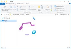
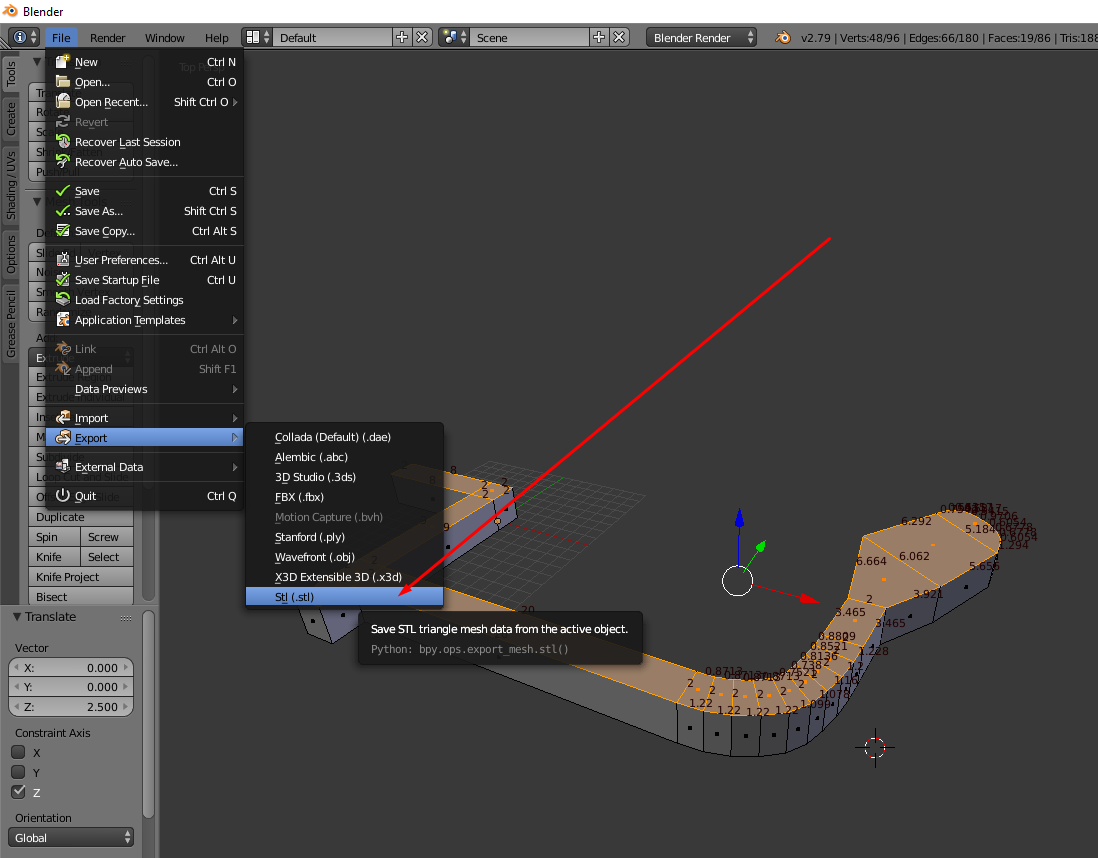
First you need to export our creation to an .STL file:
When saving the exported STL we can select various options. But we will not need them now:
The only option worth remembering is "Selection Only", which allows us to export only what we have selected in the scene to the STL file. This will come in handy when we have several objects in the scene and only want to print one.
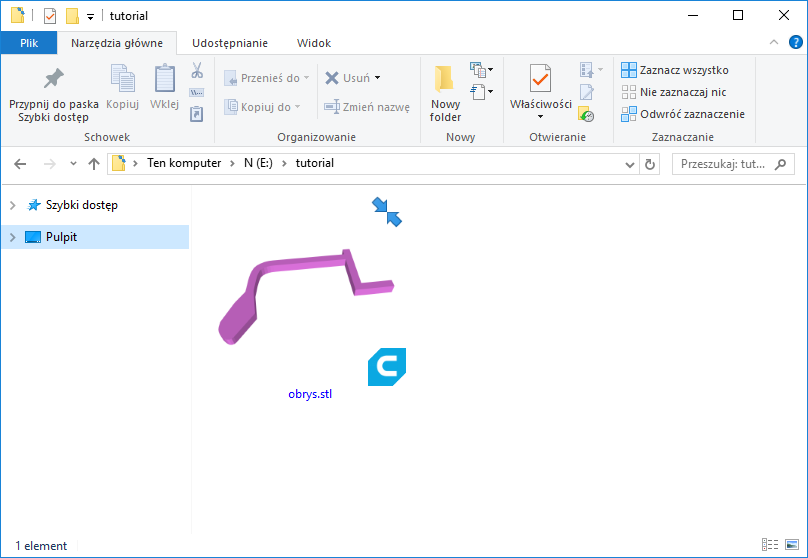
In this way we obtain an STL file:
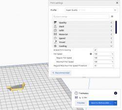
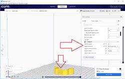
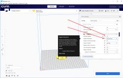
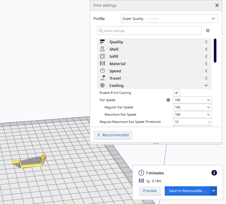
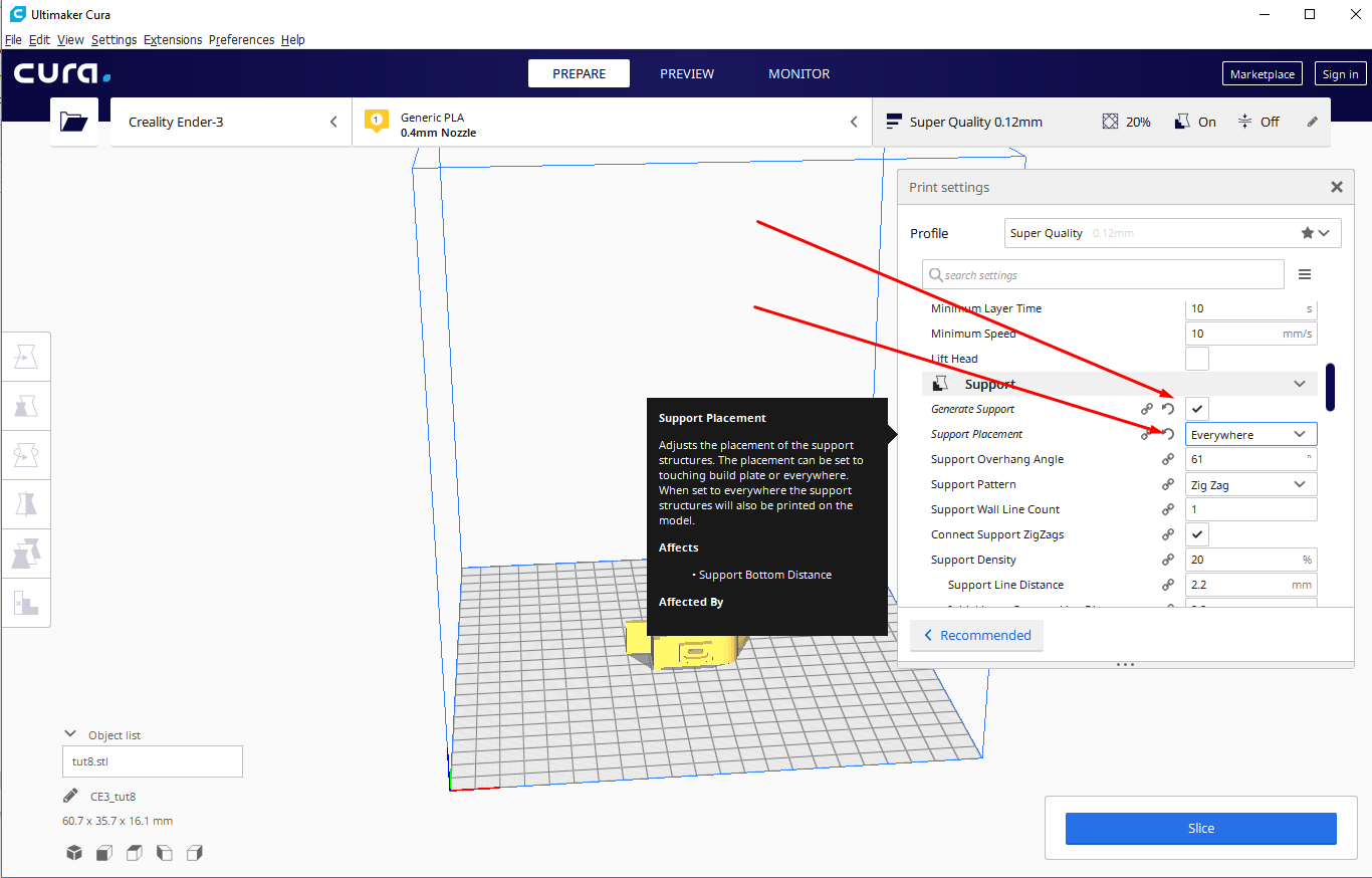
It now needs to be opened in our preferred slicer (I use Cura) and exported to GCode, on the SD card. I used the default 'Super Quality' options:
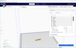
I already had the SD card connected to the computer, so after Slice I could immediately save the result to it:
We put the card with the SD into the printer and simply print our object from the list.

In my case, for the first test print it turned out that I had slightly underestimated the dimensions. I had to scale the whole object. This can easily be done by selecting the whole thing (I recommend scaling in Edit Mode, not in Object; select everything with the A key) and then pressing the S (Scale) key, then typing in the new scale from the keyboard (e.g. press S and then type 1.2 to get 120% scale).
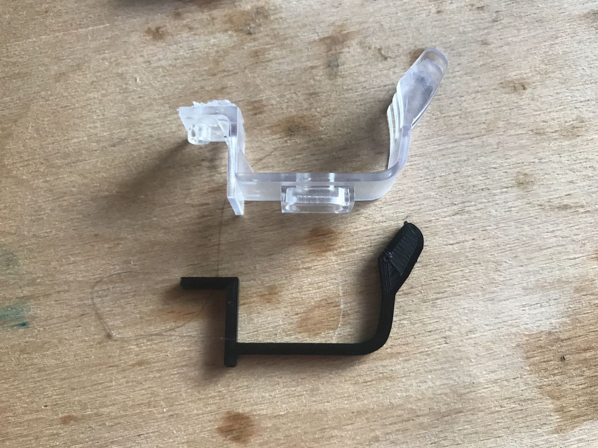
After the scale corrections, I re-printed the part and compared what I already have modelled to the abutment I am trying to reproduce:


The shape of the element has been well mapped, you can proceed to the next modelling step.
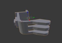
Step 14: Mirror (mirror)
At this point we can take advantage of the fact that the object to be modelled has a single plane of symmetry and apply a so-called mirror. We will model only one side of it, and the other side will be its mirror image.
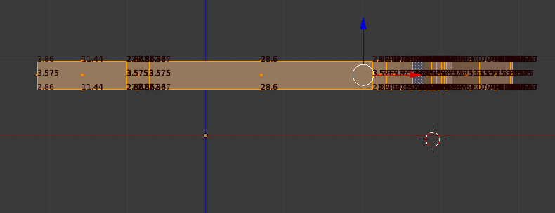
Mirror in Blender works relative to the centre of the coordinate system of the current model. To do this, we will move the object a little lower by selecting it in its entirety and then pressing G (grab, move) and typing Z (the axis along which we are moving) and then 5 (the value of the shift - so that there is about 8mm from the centre of the coordinate system to the top edge of the model:

Now you can add the mirror image.
The mirror image in Blender is created on the fly and we can edit one side of the model.
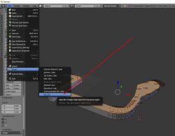
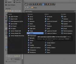
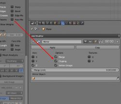
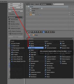
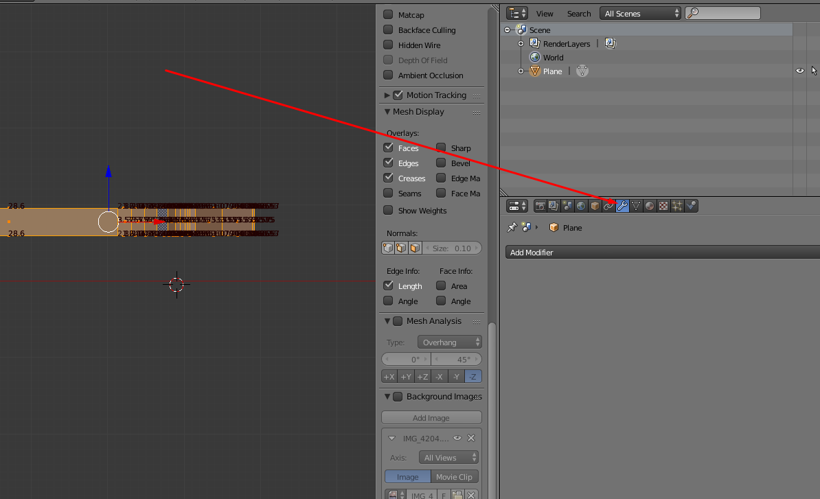
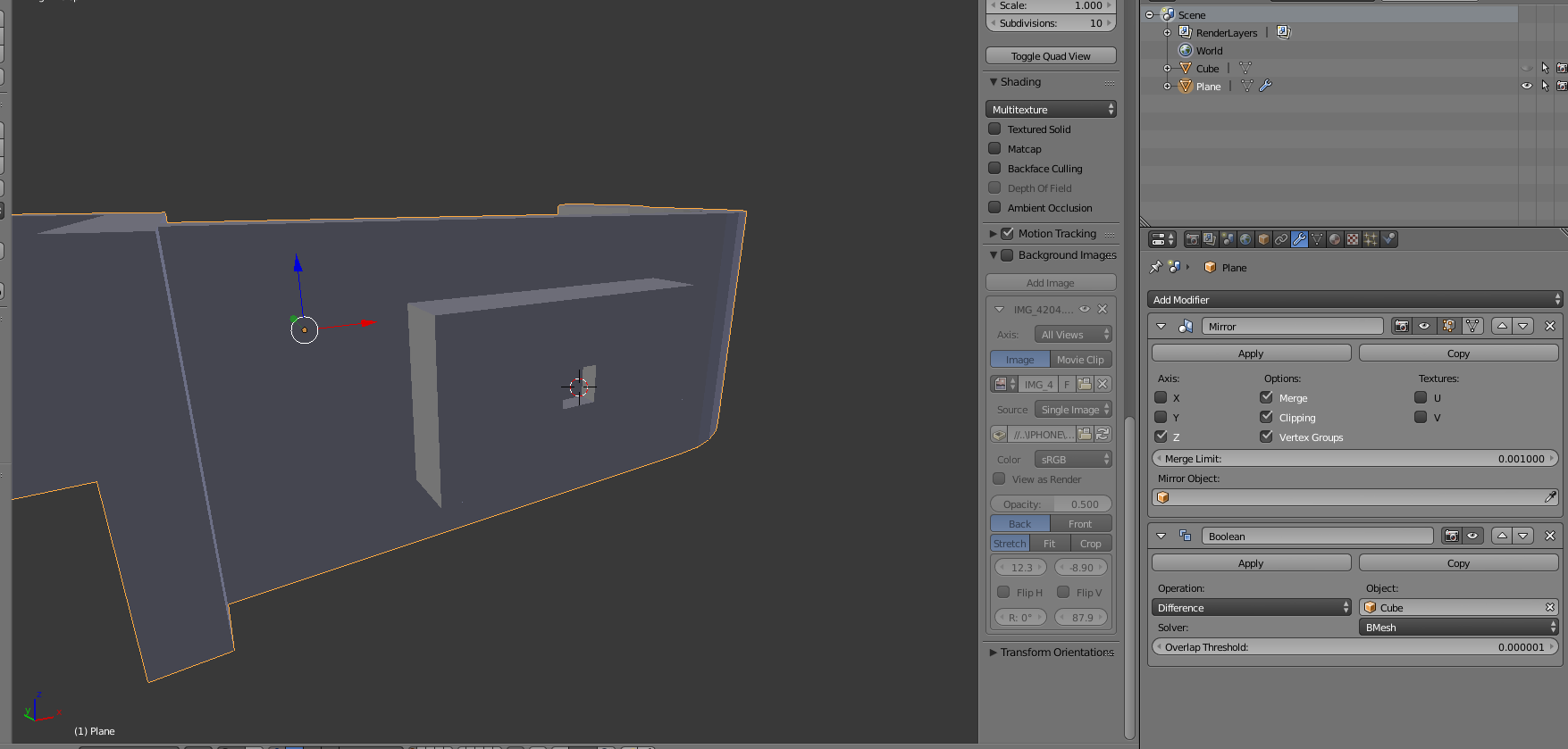
The mirror is added as a so-called modifier from this menu:
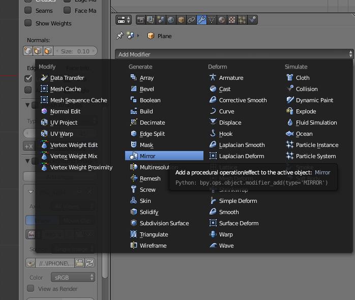
We select 'Mirror' from the 'Add modifier' list:
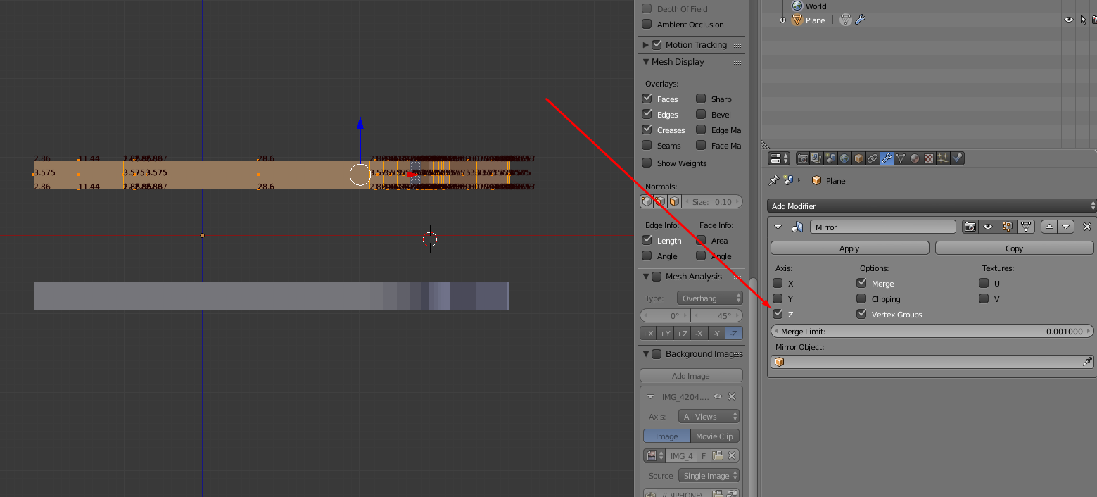
Once the Mirror has been added we configure it accordingly - we want a Z-axis reflection:

And then we DO NOT CLICK 'Apply', but leave it as it is - this way the mirror will reflect our changes one side at a time. If we clicked 'Apply', however, then Blender would process the mirror and create normal geometry from it which we can edit, but which does not update itself after changes from the other side.
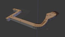
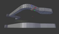
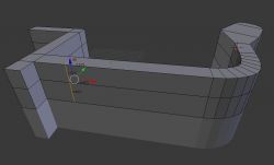
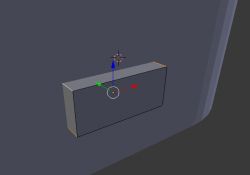
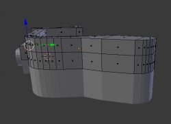
Step 15: First full 3D shape
We now have something like this:
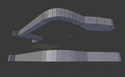
We want to merge the object with its reflection.
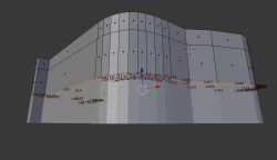
To do this, we right-click one of the walls in selection mode:
And then press CTRL + SHIFT + ALT + F to select the other walls connected to it on its plane (you can also select manually, but this keyboard shortcut speeds things up a lot):
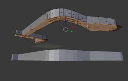
Then don't move them, but do Extrude (E) and only move them down:
 Step 16: Correction of overlapping walls with Mirror
You may now notice that the drawn walls of both sides of the mirror overlap. This is not the desired effect, but can be easily fixed.
Turn on Clipping in the Mirror settings:
Then move the inner walls upwards as far as they will go (G-Z and move with the mouse, or just click and pull on the blue Z axis):
In this situation, the Clipping setting with Mirror will not allow us to move the walls too far. Their edges will "stick" to their Mirror-generated counterparts.
The inner walls can then be removed (Delete key and Faces selected):
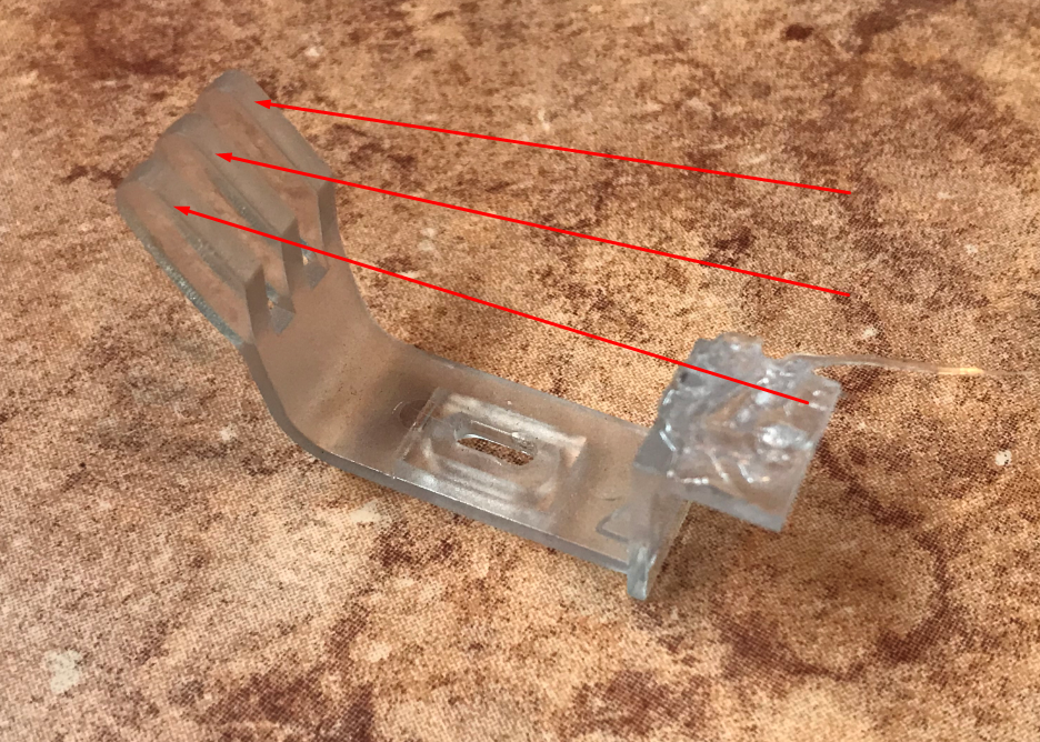
 Step 17: We map the attachment
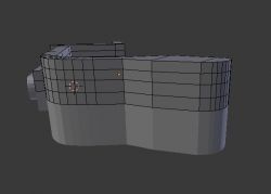
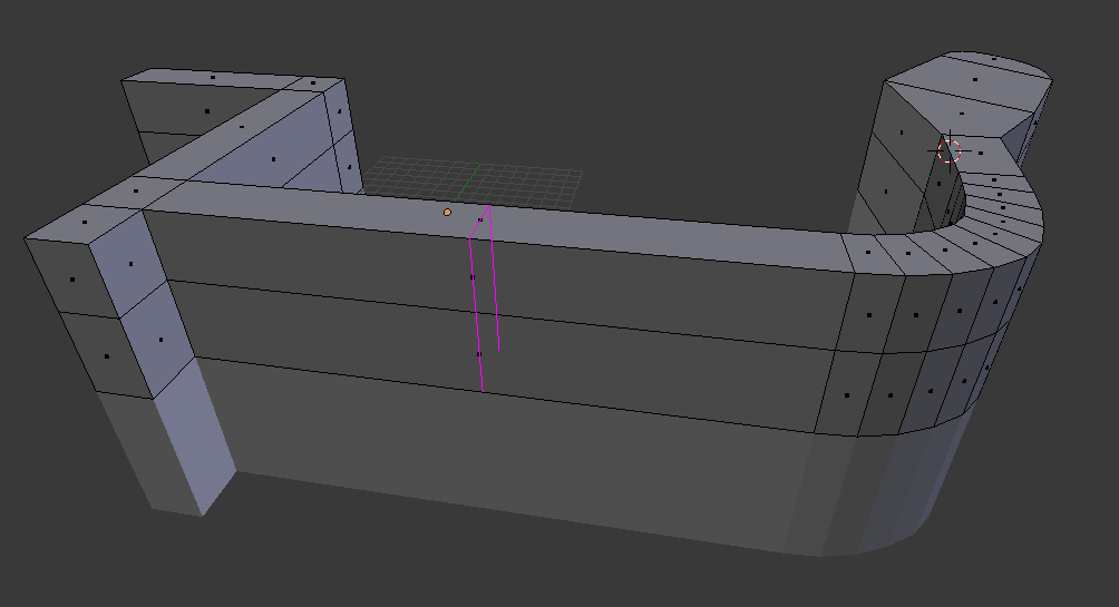
We will now map this section:

To do this, we need to thicken the model mesh. This can be done by adding cross-cuts using the Loop Cut And Slide option (CTRL + R):
Once you have accepted the cut with the LMB, you can move its line with mouse movements. Then you have to press LMB again.
First cut:
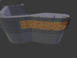
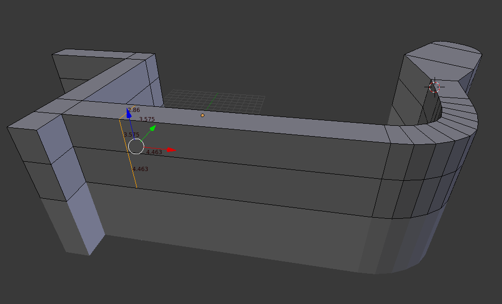
Now we will add a second cut - I will explain how we will use it in a moment:

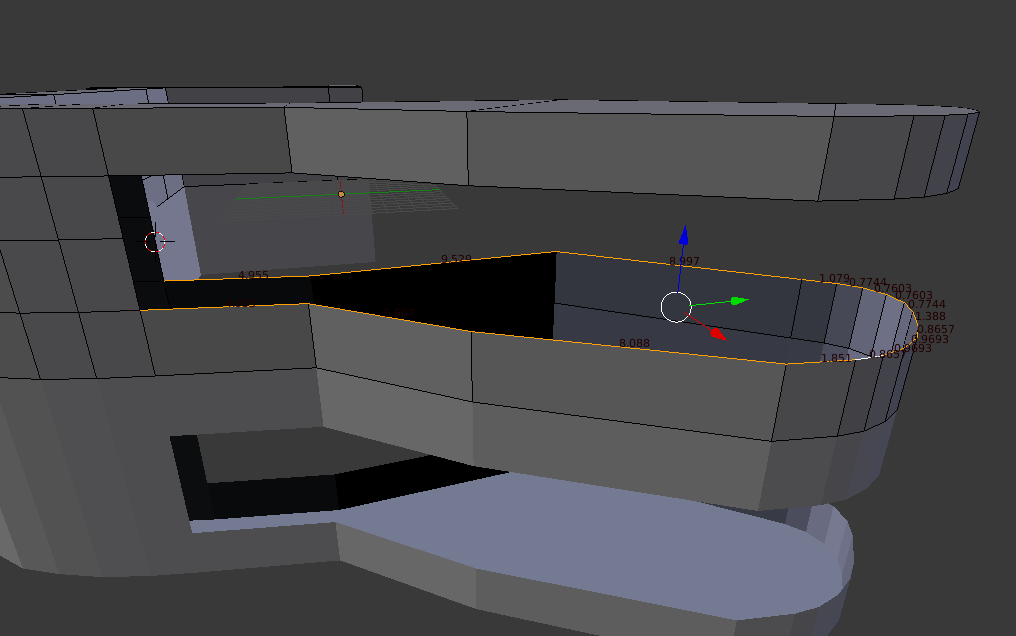
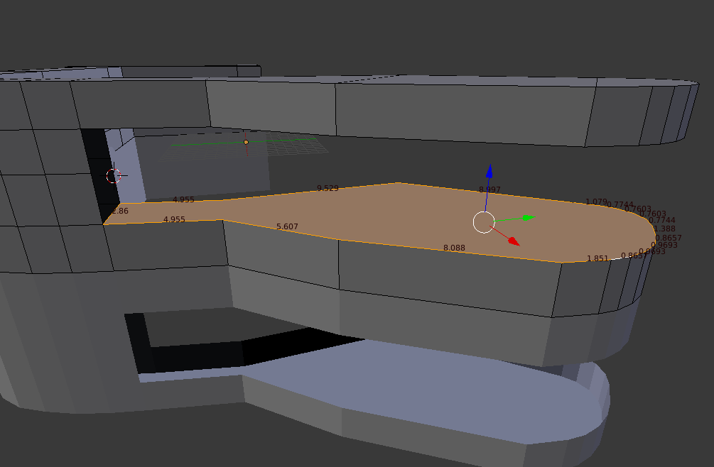
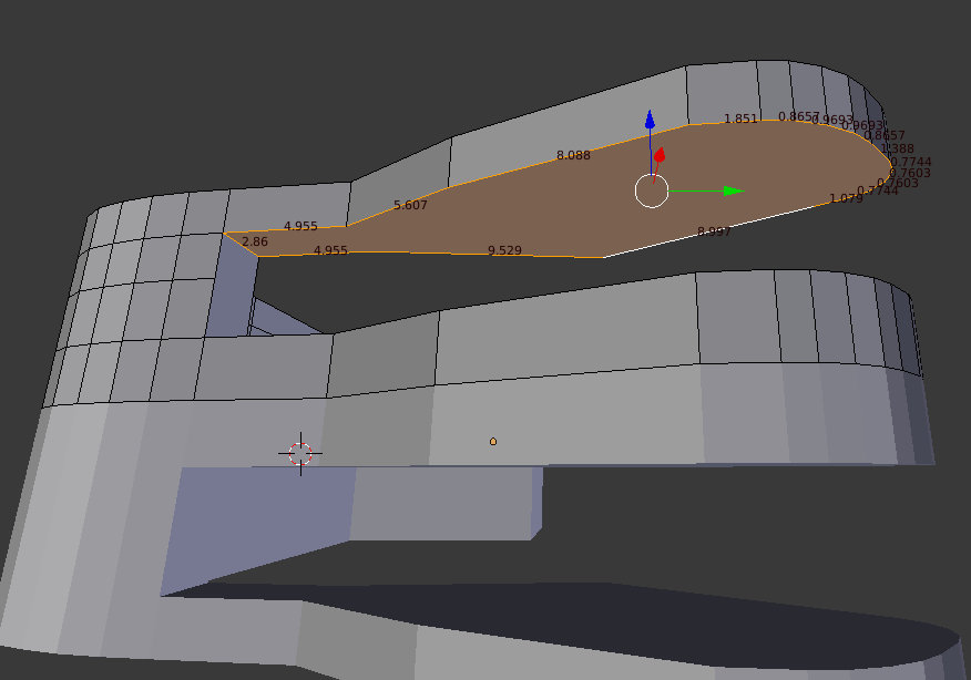
Now you can select the middle face (in face, face selection mode) and use Extrude to draw it out.
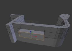
Of course, even after this operation we can correct the dimensions of our extrude so that it is as expected.
Step 18: Check the dimensions
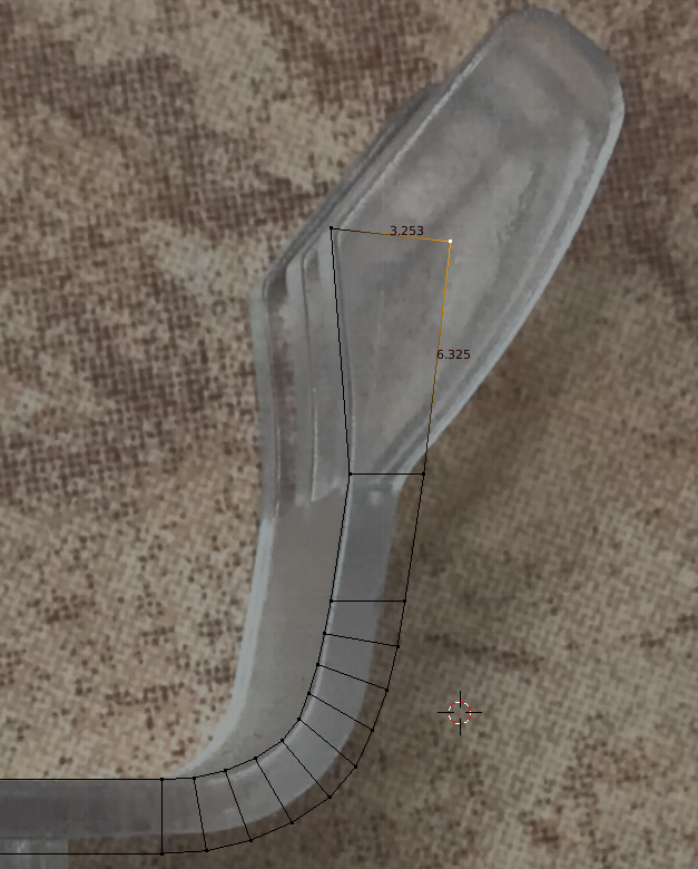
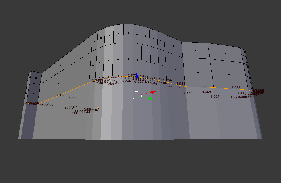
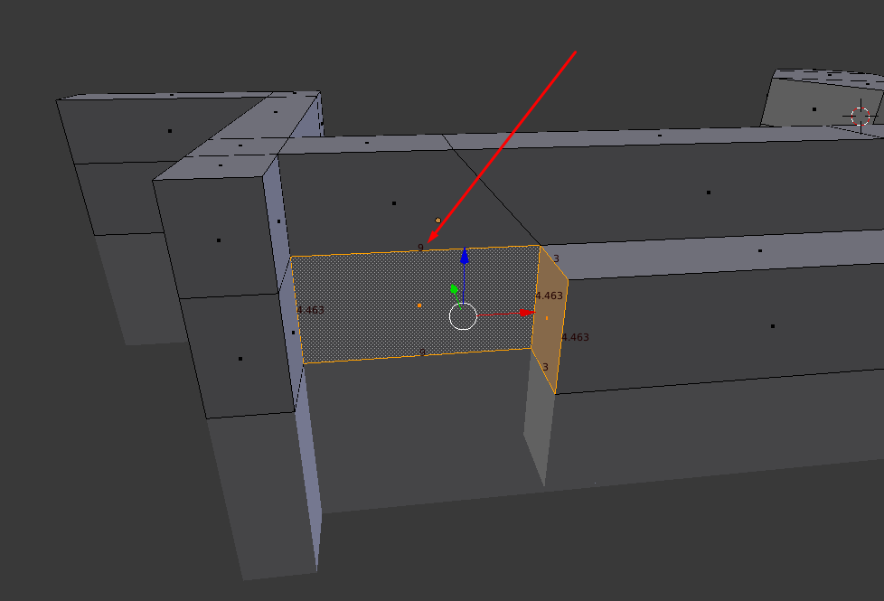
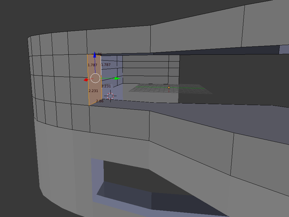
Now I'm just going to highlight something I've introduced before. As you enter the dimensions and add more walls, it is a good idea to verify that the spacing is correct.
For example this dimension:
It is compatible with:

Adjust walls/move if necessary
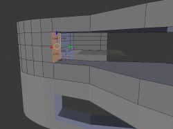
Step 19: Cutting a hole in the mount using a boolean - adding a cutout object
Now we will cut the hole for the mount/screw. I will specifically use the boolean operation for this to demonstrate how it works. Of course, this could also be done without boolean.
We will carry out the cutting out using the second object.
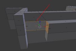
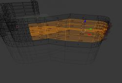
We select the middle edge:
We press SHIFT + S and choose to position the 3D cursor on our selection:
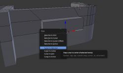
This way we won't have to manually centre the clipping object.
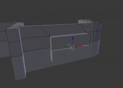
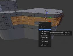
We switch to Object Mode (because we're about to add a second object):
We add the object that will be cut from our model via SHIFT + A:
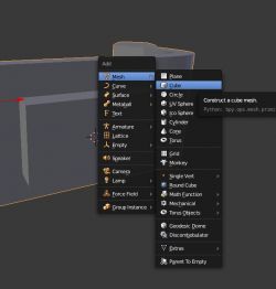
NOTE: If we do a SHIFT + A (add) in Edit Mode, then the added geometry will be within the same object we are editing, and we won't be able to do a boolean operation, because you need two separate objects for it.
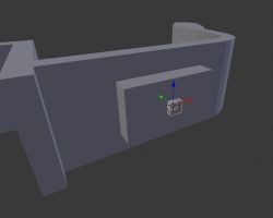
The object is added where we had the cursor:
 Step 20: Cutting a hole in the cradle using a boolean - setting the boolean
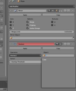
We will now set up a boolean operation (Boolean operations, in subtraction mode, cutting out) for the objects we have.
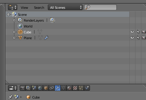
We should have two objects in the scene (the cutting object and the one we will cut from):
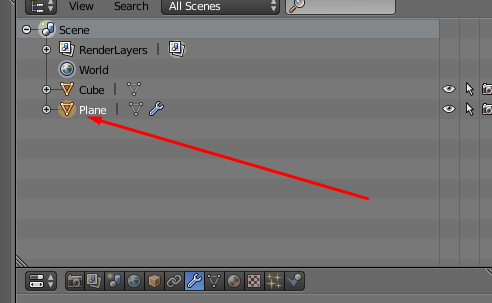
We select the object from which we will cut:
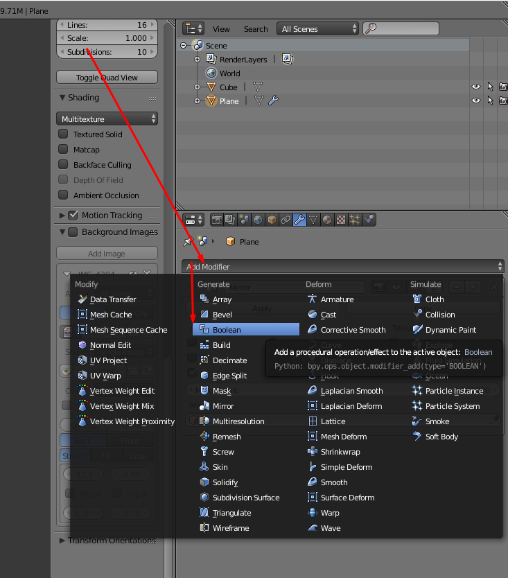
It is on this object that we add the Boolean modifier:
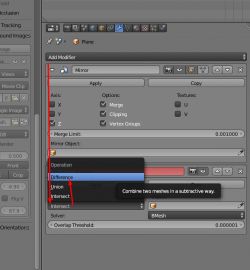
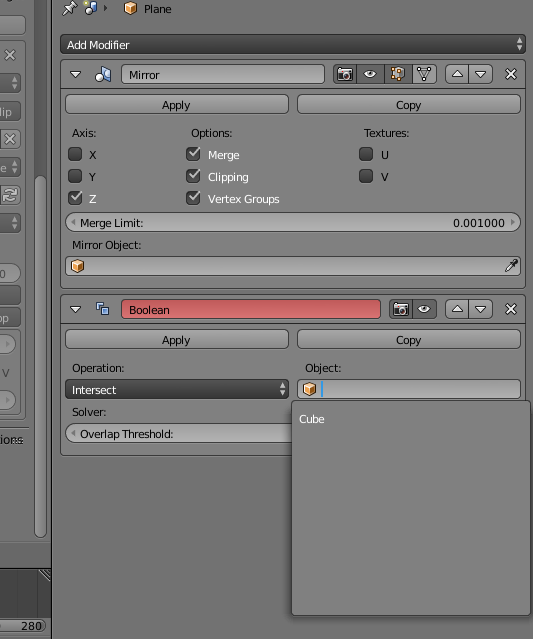
The boolean modifier needs to be set appropriately. We set it to difference mode:
and set the object that will now be cut from our selection:
We can now select the clipping object and hide it from view with H (SHIFT + H will bring it back into view) to see the clipping effect:
The Boolean works - the object has been cut out of our shape.
It is worth noting that the Boolean results can only be seen in Object Mode. In Edit mode there will be no cutout.
Step 21: Cutting a hole in the base using the boolean - cutout shape
Now we can appropriately modify the shape of the cutout object so that it matches what we expect from the element.
I'm not going to describe this in detail, as you can use the mechanics learned earlier in this description to do so.
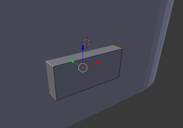
But in brief, I started by stretching (scaling) the Cube:
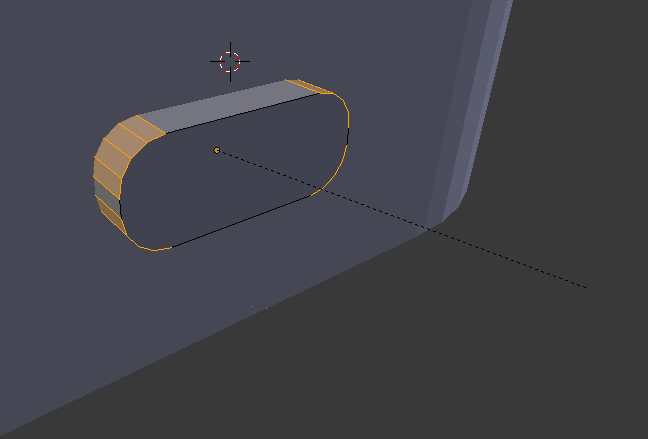
Then I selected four of its edges and, as earlier in the tutorial, used the Bevel tool (CTRL + B, because here for edges) to round them off:

I then used the Extrude option and reduced the scale of the wall to start making the piping:
I then extended it again using Extrude:
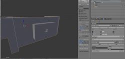
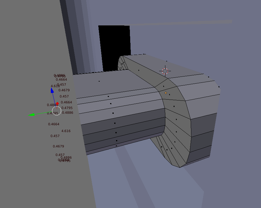
Then you can admire the result of the clipping - to do this, you have to switch to Object Mode and hide the clipping object with the H key. Then only the object from which the shape was clipped will remain on the scene. The result (from below):
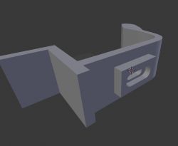
Result (from above):
 Step 22: Functional print
The component can now function as a lampshade attachment. You can only print it with supports on the buildplate (then there will be supports from the base of the print to the element, but they will be missing in the hole from the element. This can only be done in certain situations. Printing such places is called 'bridging', as the printer creates a 'bridge' from the filament without support):
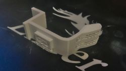
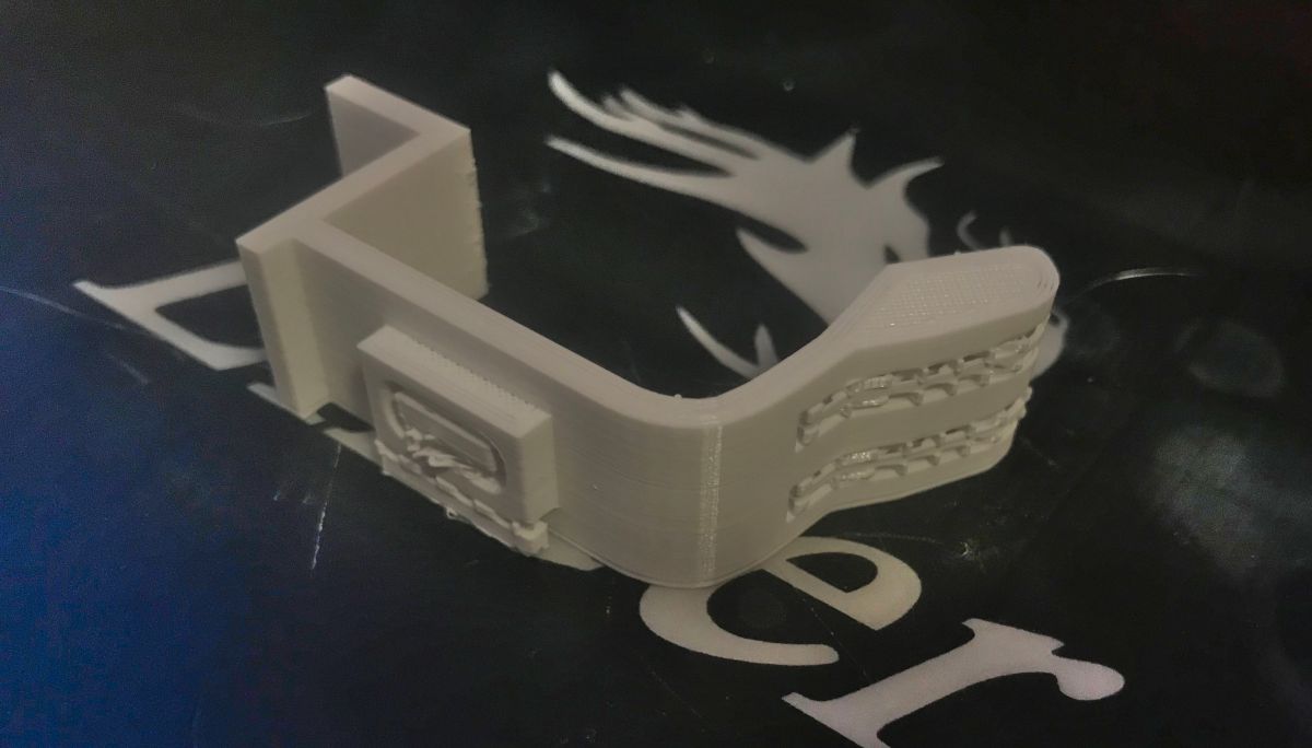
After printing:
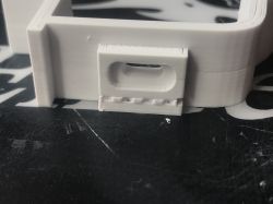
The supports can be broken out of the piece very easily, I used a knife for this. The fitting:
 Step 23: Completion - three separate attachments
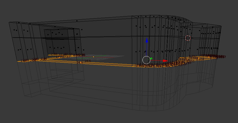
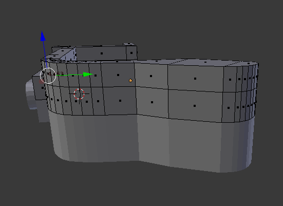
Now I will still show how you can make three separate abutments instead of one thick one, i.e. how to divide this abutment what we already have. We are talking about these abutments:

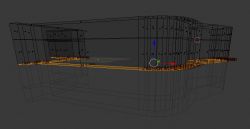
To do this, I will first add two cuts along the model (Loop Cut and Slide, CTRL + R). Before:
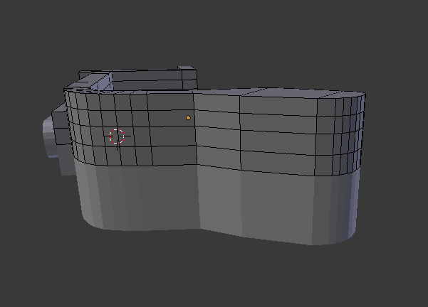
The location of the Loop Cut And Slide is controlled with the mouse. After cuts:
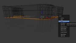
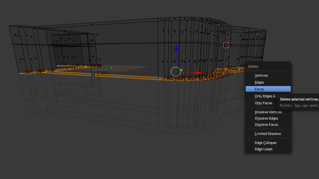
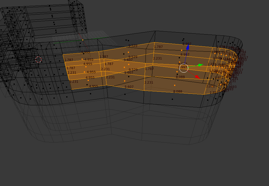
I will then select the walls, which I will then remove (RMB selects one wall; SHIFT + RMB selects the next; you can also select in another way - holding C and LMB, the so-called drag selection):
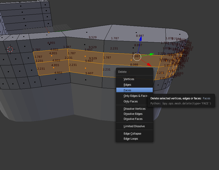
They can be deleted with the Delete key:
The next step is to fill in the cavity. To do this, we will first select the edges that are on the same plane:

And then we will fill in the empty space between them with the F key, creating another wall:
Same for the small wall:
And for the other side:
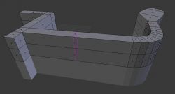
We can then adjust the thickness of the elements by simply moving the corresponding walls along an axis.
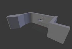
The result:
 Step 24: Final version, final print
I had to print the final version already with full supports (not only on the buildplate) due to the 'teeth' division:
After printing:
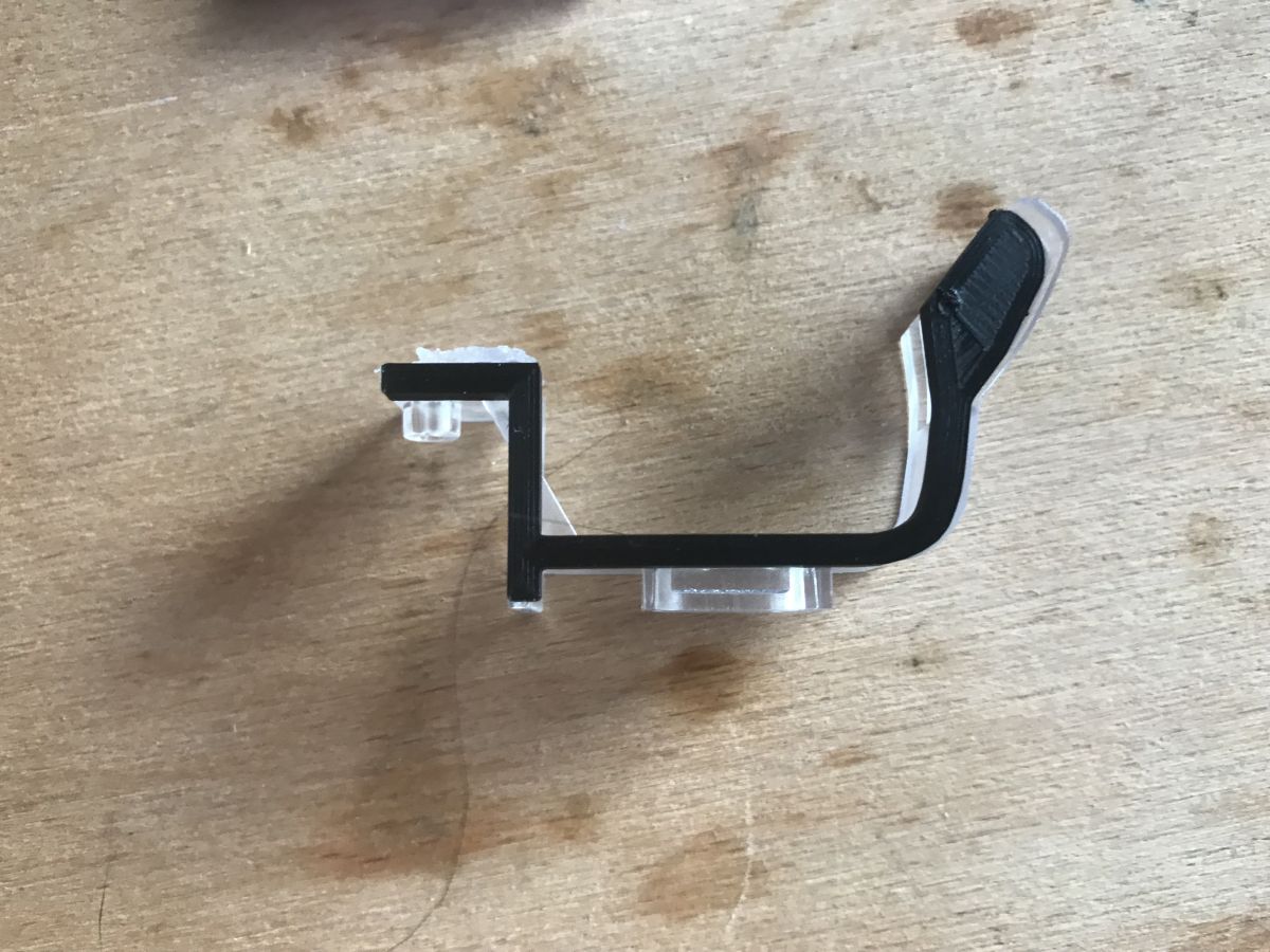
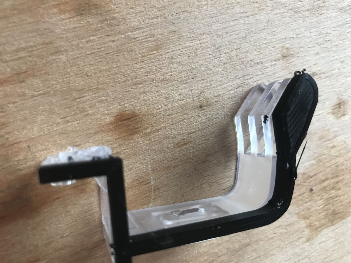
Fitment:

Final result:
The printed piece fits the lamp and does its job well.
Summary
Here I have shown step-by-step how to map in Blender and print on a 3D printer the missing attachment for the lamp. I based the mapping on a photo to keep the proportions correct. Done this way, the element is functional and holds the lampshade well. In fact, it is even better because it is more resilient - the original one broke quite quickly. On the other hand, if you find that you need a more solid element, you can always print it in ABS instead of PLA, for example, and/or set it with a larger infill.
This topic will be edited/revised in the future 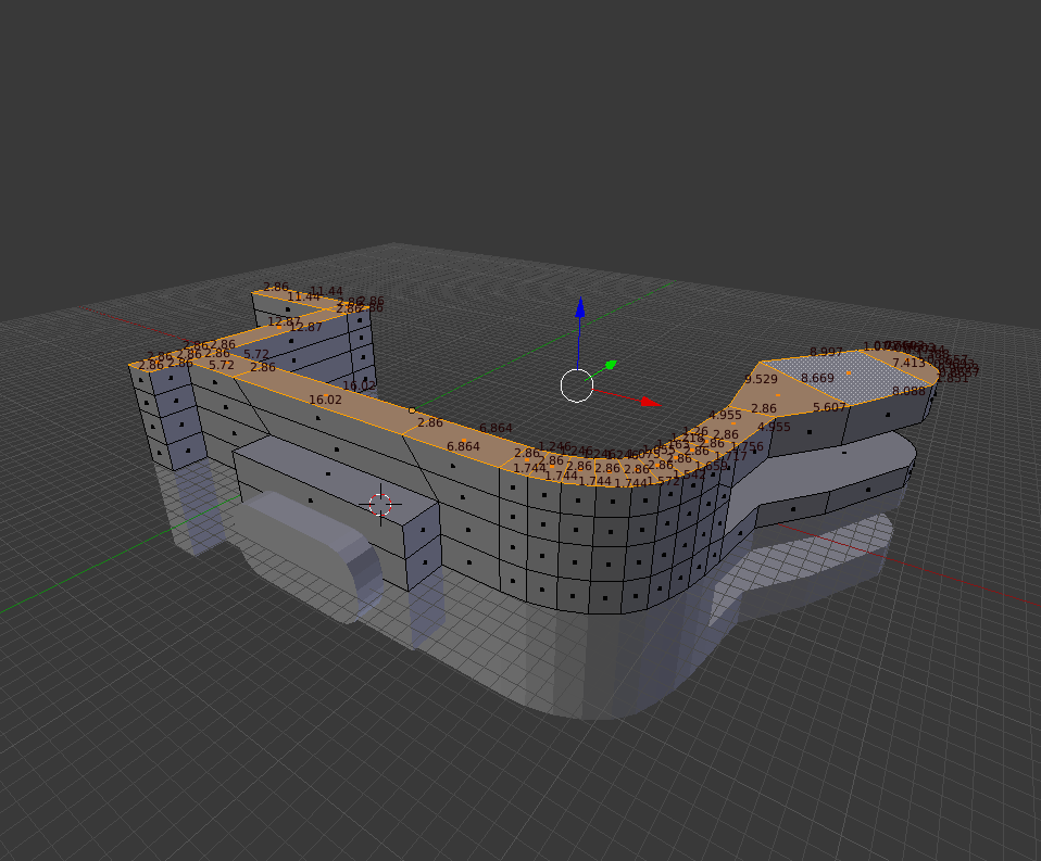


Comments
Mr. @p.kaczmarek2 , scanner, does that tell you something? :D In all seriousness, when you scan an object with a regular scanner you get an accurate outline that is not spoiled by perspective, as... [Read more]
Absolutely right point, I was even going to mention it but I think I missed it. I haven't used a scanner myself, because I don't even have one connected. The scanner and printer have gone out of use... [Read more]
@kaczmarek2 But of course it can be done in Blender, 3D Studio etc. In fact, you can also hammer a nail with your head if you are stubborn, but it is better to reach for the hammer ;) Here as well,... [Read more]
In my opinion, the wrong tool for this type of project. Blender/3DSM are sensational when it comes to organic objects - in any other case, a soft created for parametric representation of shapes is the... [Read more]
Interesting use of Blender in a different environment than it was intended, respect. From my side I can recommend FreeCAD for this kind of work, better IMO, and also open source and free like Blender ... [Read more]
Very interesting article. But could you explain the test print option in more detail? I don't see any settings that suggest a simplified print (on the contrary you select Super Quality). How does this... [Read more]
It's not an option from Cura or Blender, it's just what I call the habit of printing a part of the model only at the beginning of its creation, just to compare the dimensions to see if everything matches... [Read more]
Good approach and I also do it that way - also you can test yourself by printing from any layer, i.e. e.g. the top part if there are any important details to be measured there, or to check if they fit... [Read more]
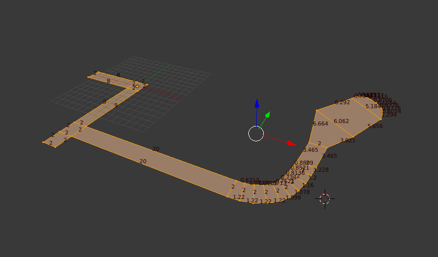
Splitting by layers is easy and convenient, but it is also worth knowing that you can test print parts of the model from different layers. E.g. from this screenshot, just what I have highlighted in yellow: ... [Read more]
Very interesting post, I found it while looking for information on whether you can actually design something in Blender and print it out. I'm just starting to get into 3D, I've been making more artistic... [Read more]