Alteration of a jumper shaver, design and printing of a housing section
TL;DR
- A Hualing HL-677 clothes shaver lost its original non-standard power cable, so the power connector was redesigned and 3D printed instead of discarding the unit.
- The replacement part was modeled in Blender with mirror symmetry, bevels, extrudes, and boolean cuts, then fitted to the shaver’s original hooks and a salvaged radio connector.
- The shaver uses a 600mAh 1.2 Ni-Cd AA cell, and the final printed part weighed about 7 grams, with prototypes bringing total filament use to roughly 25g.
- After assembly, the shaver accepted a standard “doubles” power cable and worked again, while the connector was glued so a pressed plug would not fall into the housing.
Generated by the language model.
Hello my dears.
Here I will present another simple yet practical project for which I used 3D printing. This will be a modification of the so-called "jumper shaver", more specifically the replacement of the power connector with another, more standard one. This swap saved the shaver from being thrown away as the original non-standard power cable was lost when moving house.
NOTE: this topic will also be written "tutorial-wise", more or less step-by-step I will present the process of designing a new part in Blender, although I will not give the absolute basics here anymore as there are already other Blender tutorials of my authorship available in this section.
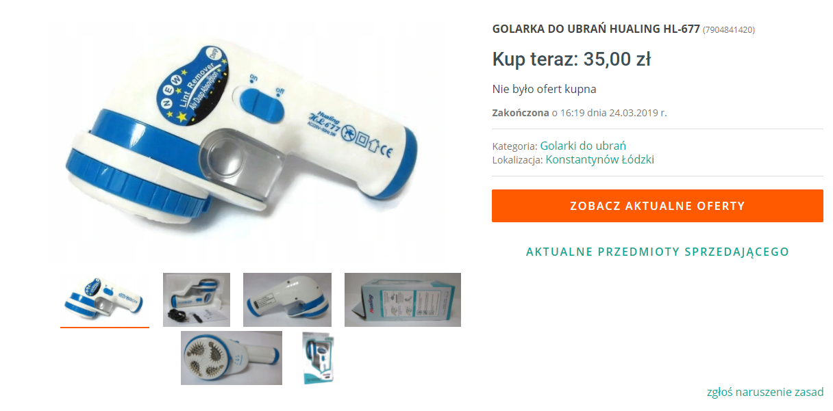
Teardown Hualing HL-677
The Hualing HL-677 is a so-called clothes shaver with a built-in, non-removable rechargeable battery. There must also be some sort of transformer inside, as we connect a 230V cable to the device to charge it, unfortunately its connector is quite non-standard. The product costs around PLN30-40:
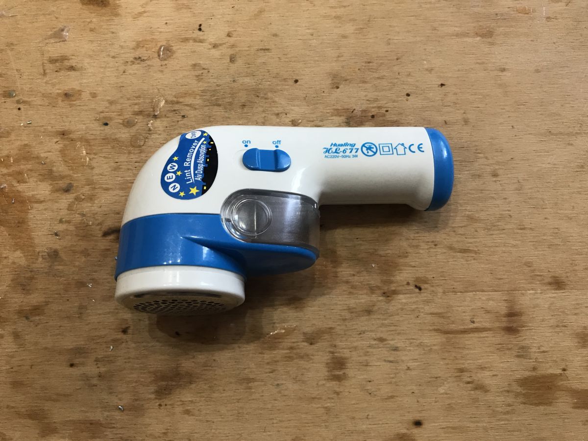
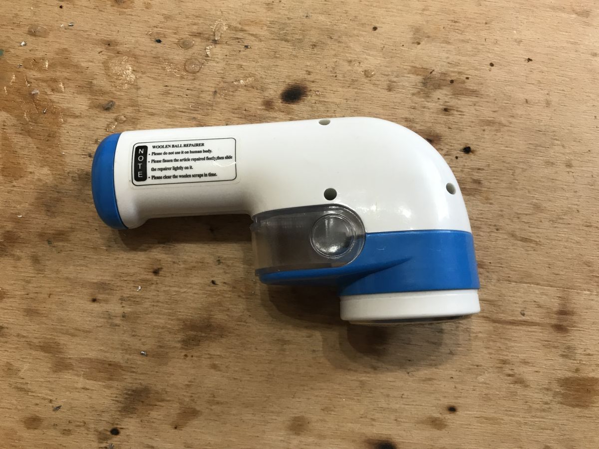
To start with, let's see how this gadget is built in general.
The knife cover is unscrewed, but this does nothing for us.
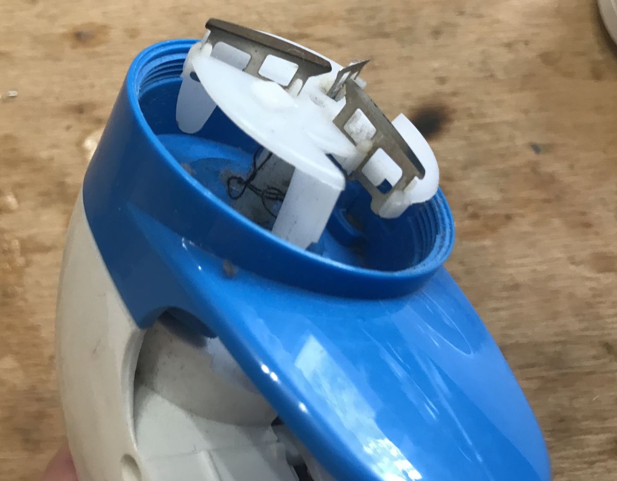
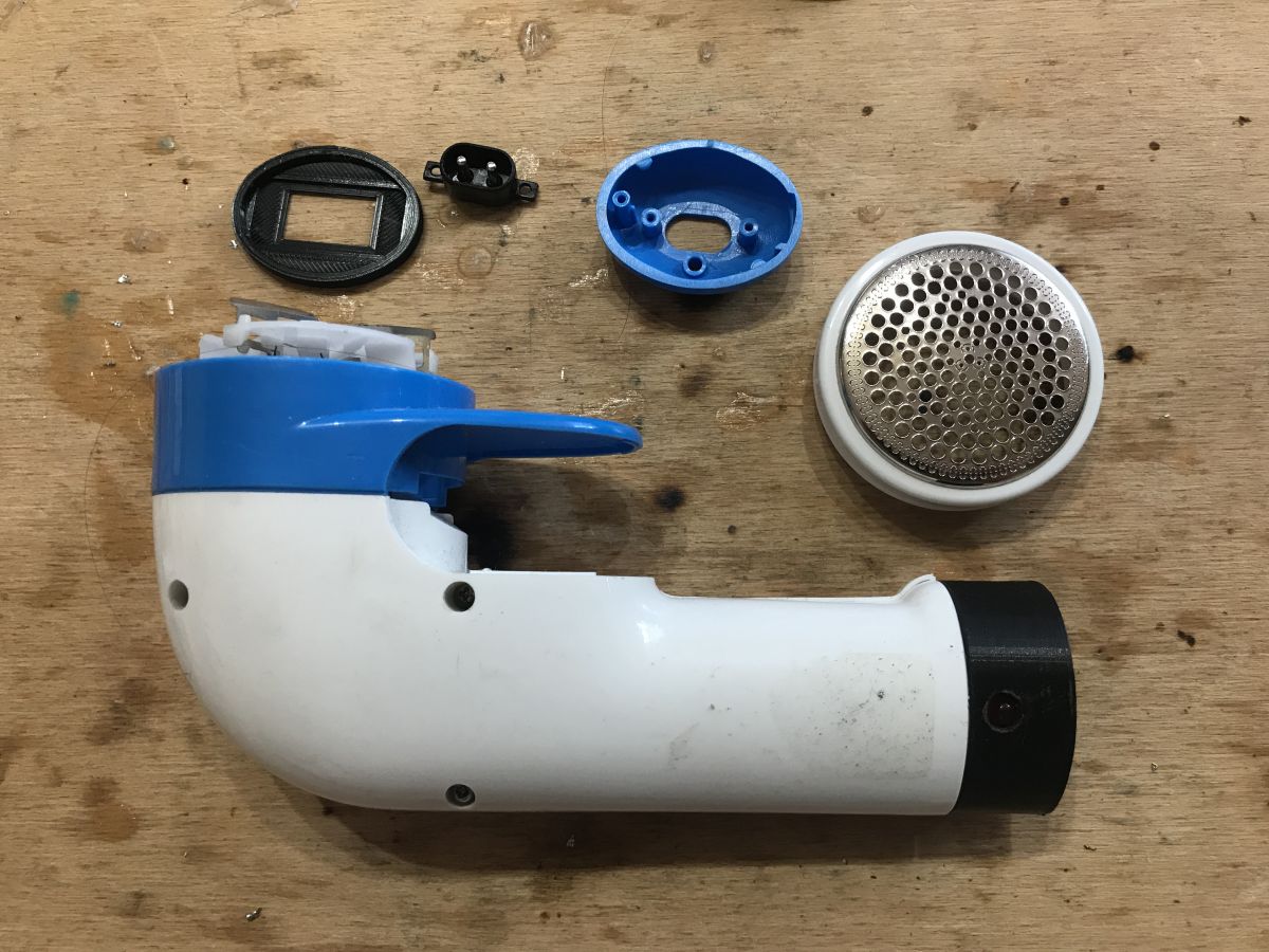
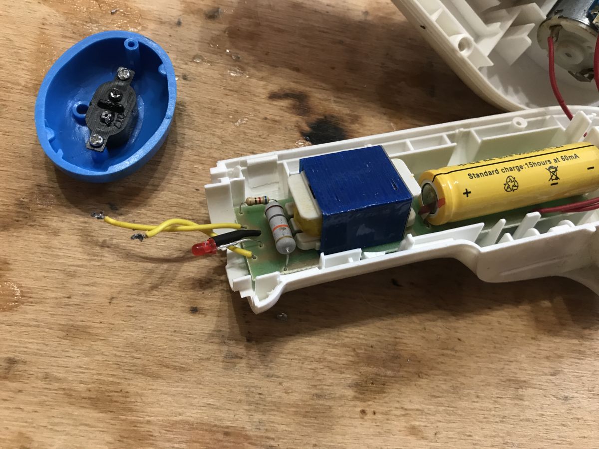
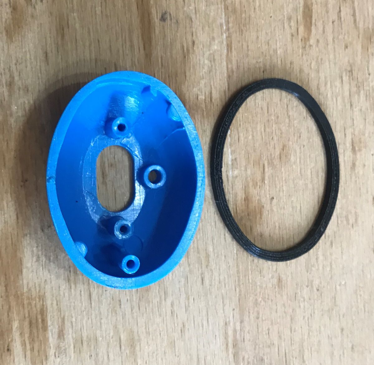
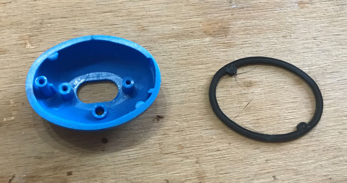
The housing is held on by three screws and a blue piece with a socket for the mains cable.
You can now see that our modification will involve printing the equivalent of the blue element.
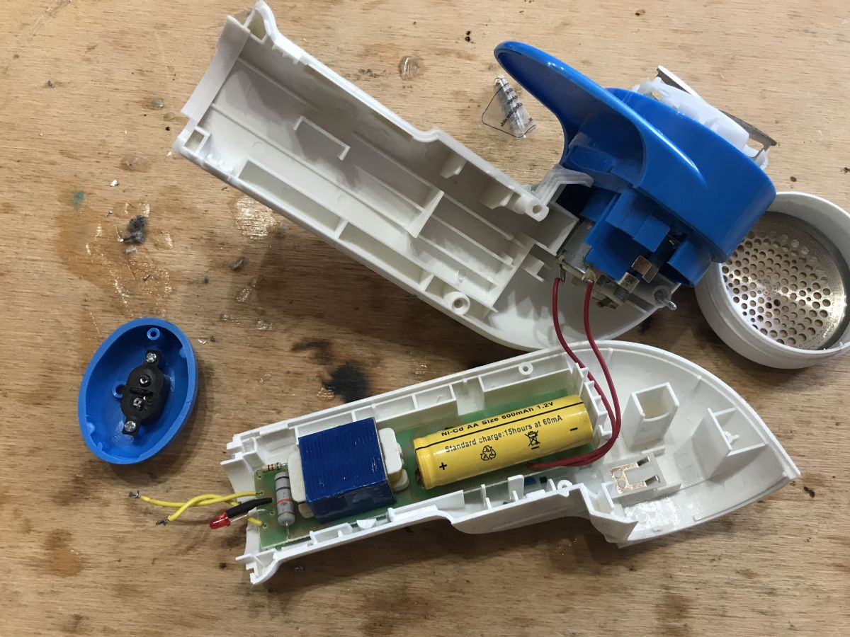
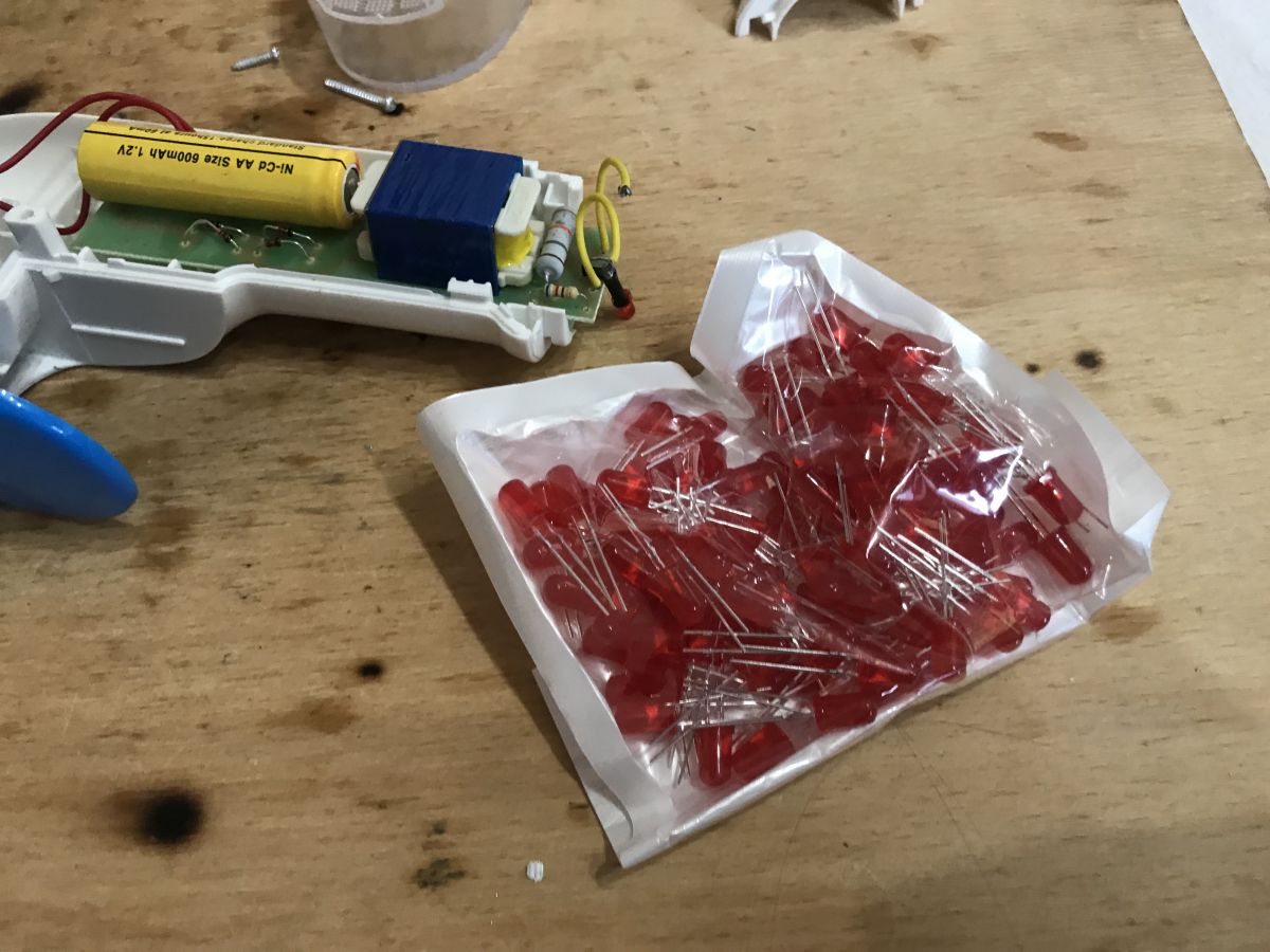
Still out of curiosity you can look at the electronics from inside:
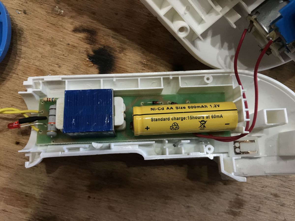
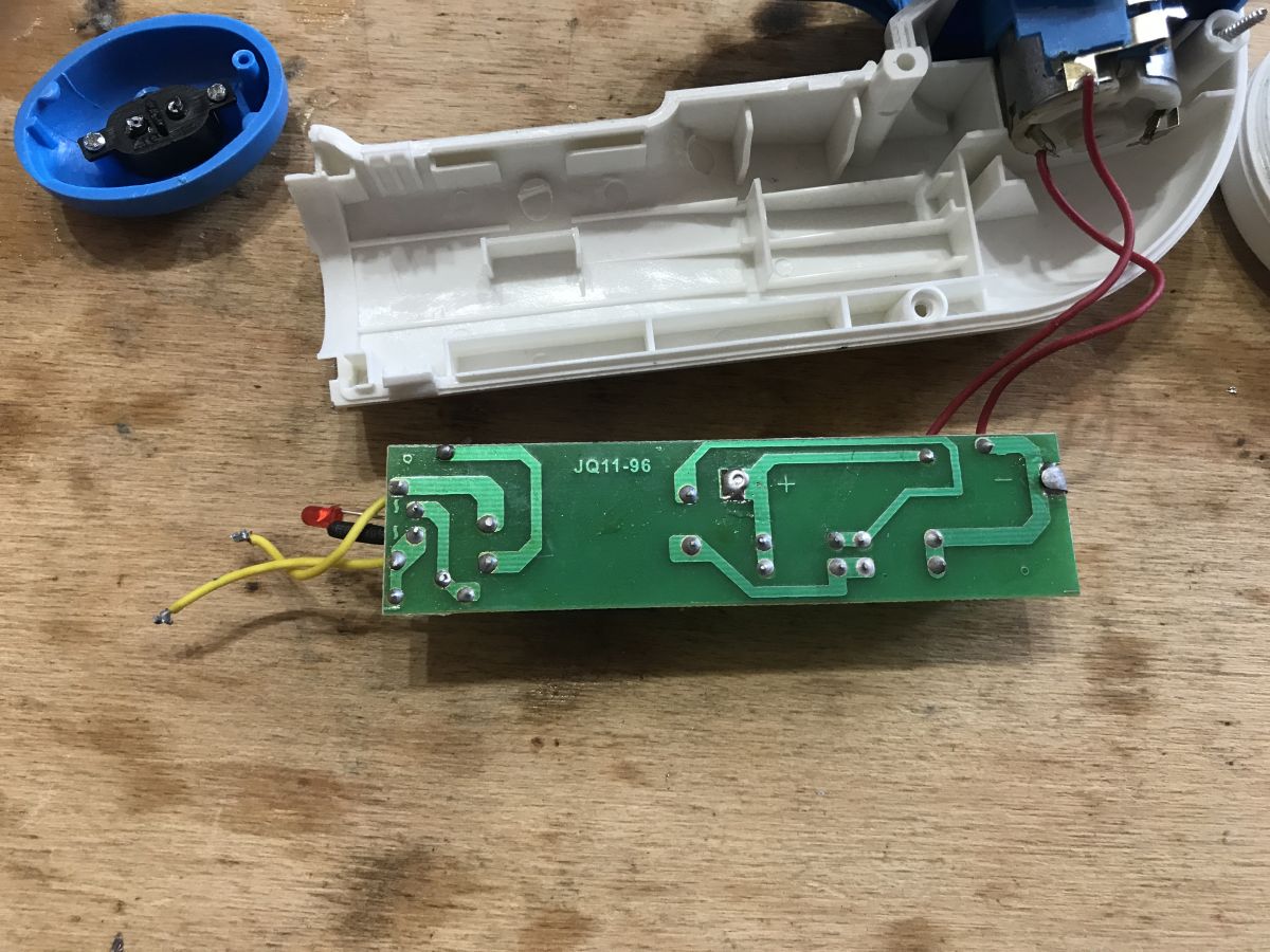
A 600mAh 1.2 Ni-Cd AA cell is used here with the charging system trimmed to the limit. Behind the transformer we only have a rectifier bridge, and in front of it an LED (which only indicates that the power supply is connected) and current limiting resistors.
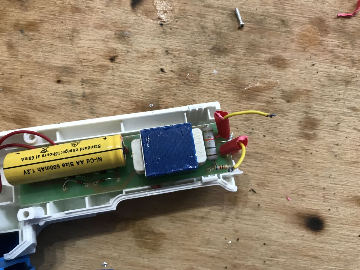
I have superimposed the component information onto the photo of the board and decoded the resistor values:
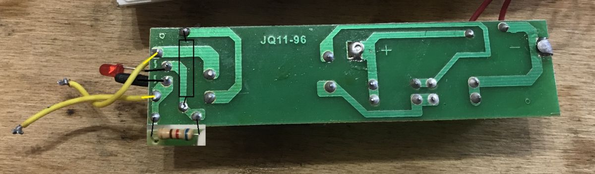
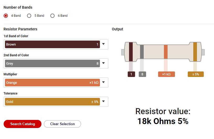
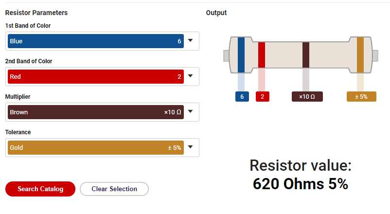
(Source: https://www.digikey.com/en/resources/conversi...ors/conversion-calculator-resistor-color-code )
Fixing design for new connector
Here I will describe step by step how I created the attachment object for the connector in Blender.
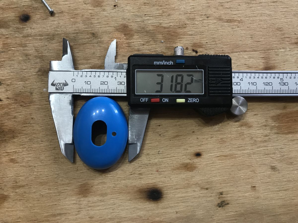
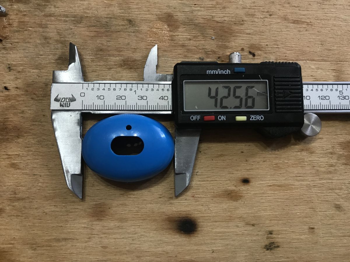
I started by dimensioning the component:
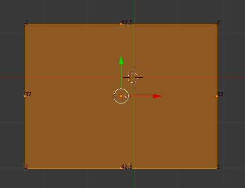
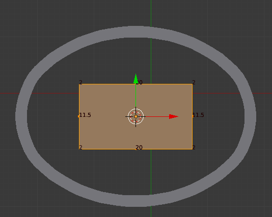
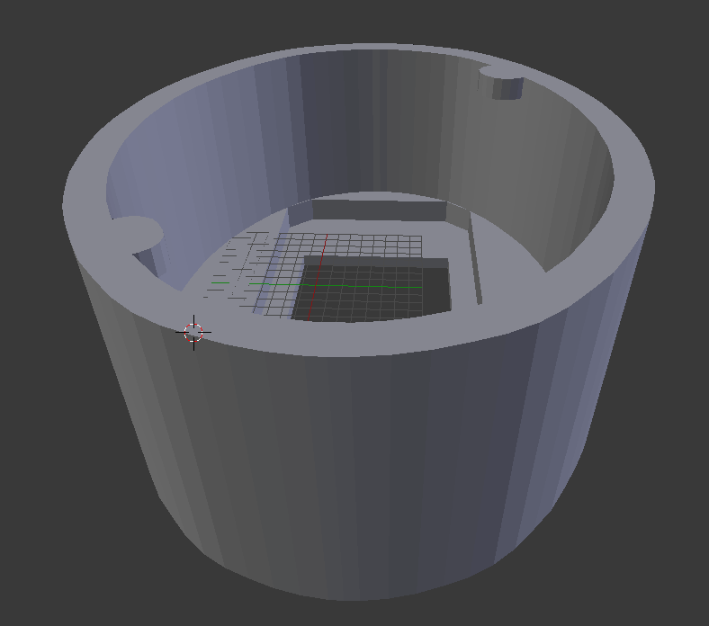
In Blender, I created a ... plane (Quad) to start with. I prepared a mirror (mirror) for it according to two axes:

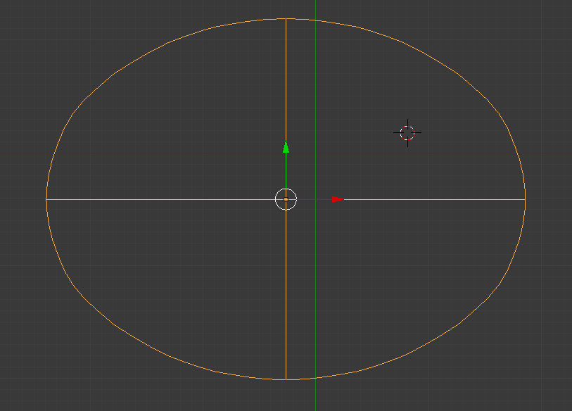
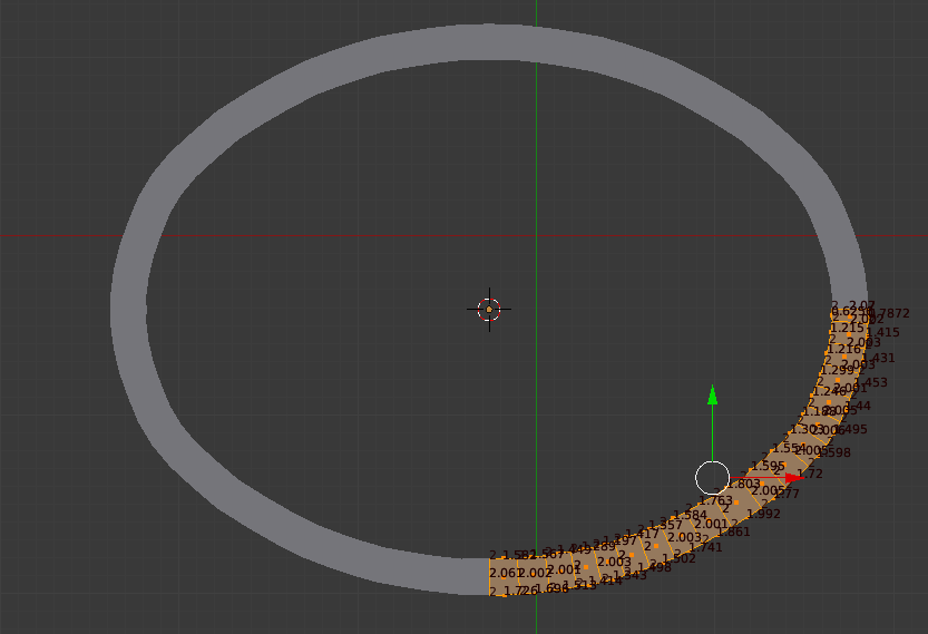
I then used the Bevel tool to do the rounding:
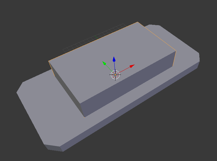
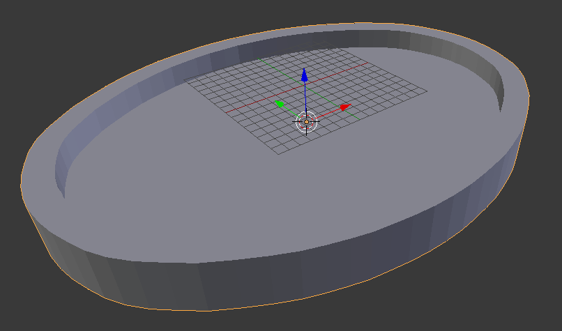
I gave the object a thickness (extrude) and then duplicated it and made the duplicate smaller, so that I could then do a Boolean difference on both to get just the housing rim I wanted to use for the test and fitting:
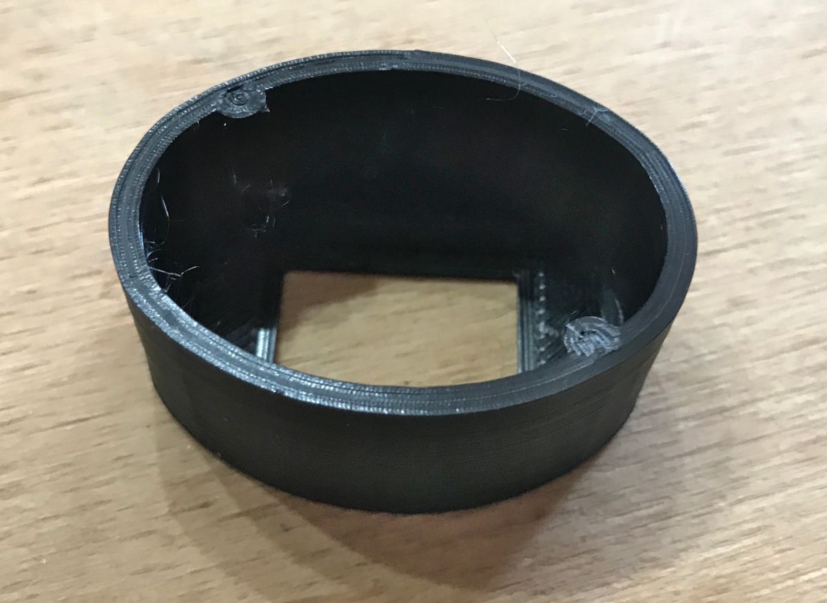
After printing - it fits ideally:

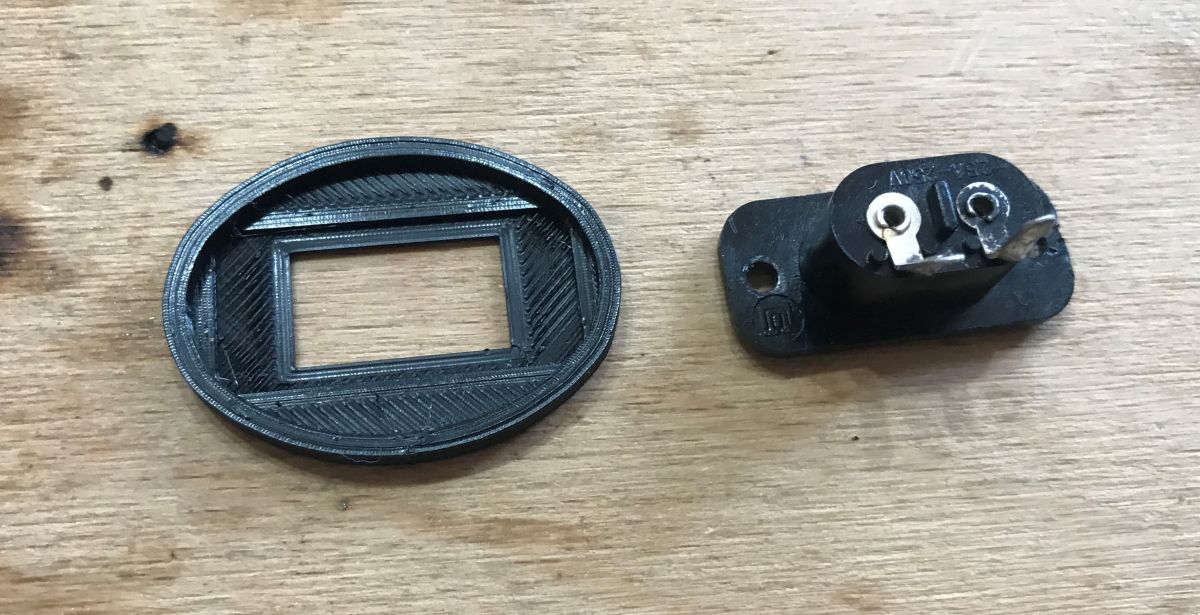
I then had to size a new socket. I took them from an old radio, I had the parts in a drawer after some teardown. I transferred the dimensions into Blender:

In the form of two elements, I modelled the connector. One will be cut from the other:
I also modelled the base of the element for the connector, without the hole:
A boolean operation (cut out) allowed me to get this result:

The connector will go in at the squeeze, but for the sake of principle it can also be glued.
Now, however, you need to think about attaching the printed part to the rest of the shaver. You can always glue, but this is rather overkill and not a recommended solution, especially as the original has hooks .
It was time to map them out. I did this by hand via extrude. I modelled the protuberance once, its duplication was done for me by Mirror.

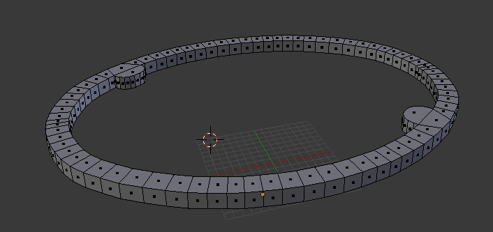
Well, and a fitting:

Fits, you can immediately combine our two objects into a whole:
Printed element:
Comparison. My element is necessarily larger, as the connector is also larger.

I made the hole for the LED with a screwdriver:

The consequence of changing the size of the part was the need to replace the LED with another one:
I used heat shrink sleeves to secure the connection:
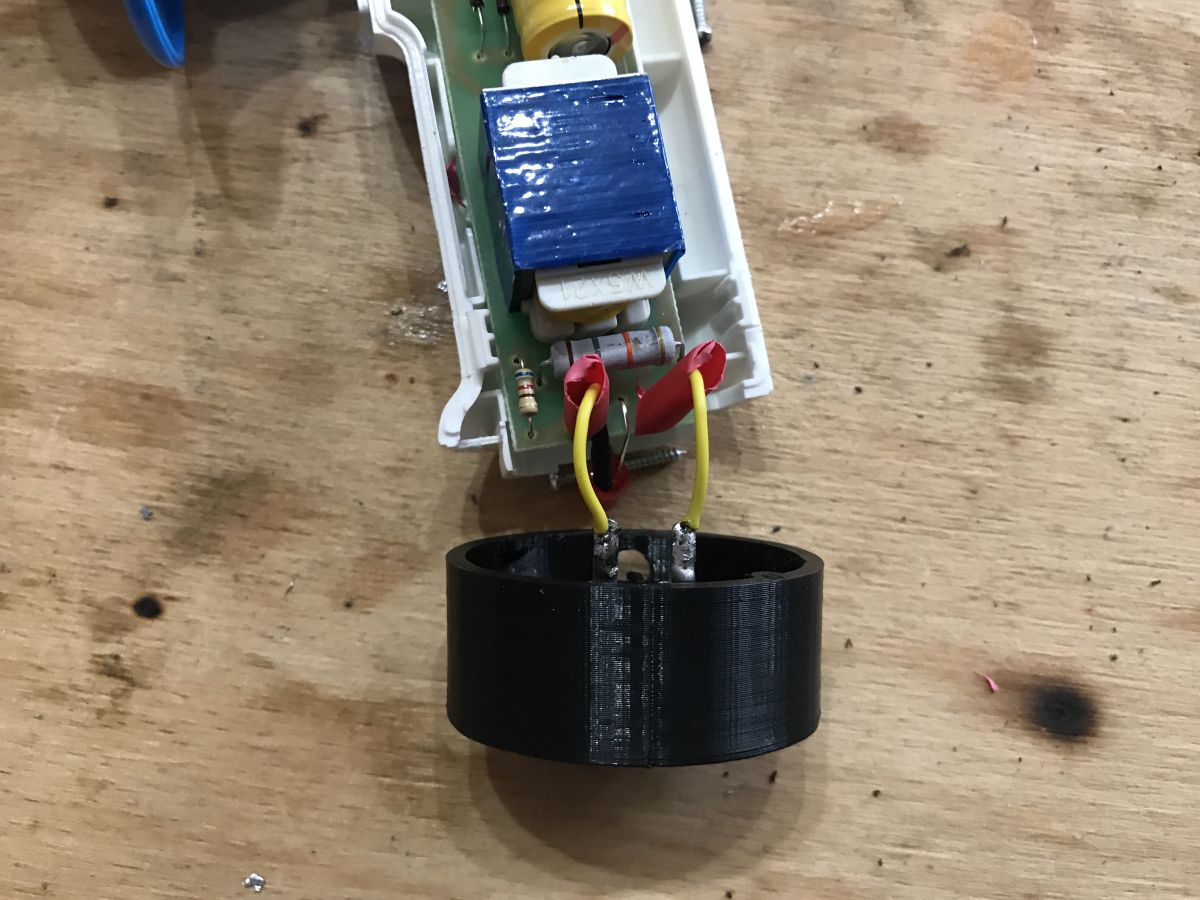
Pre-assembly test:
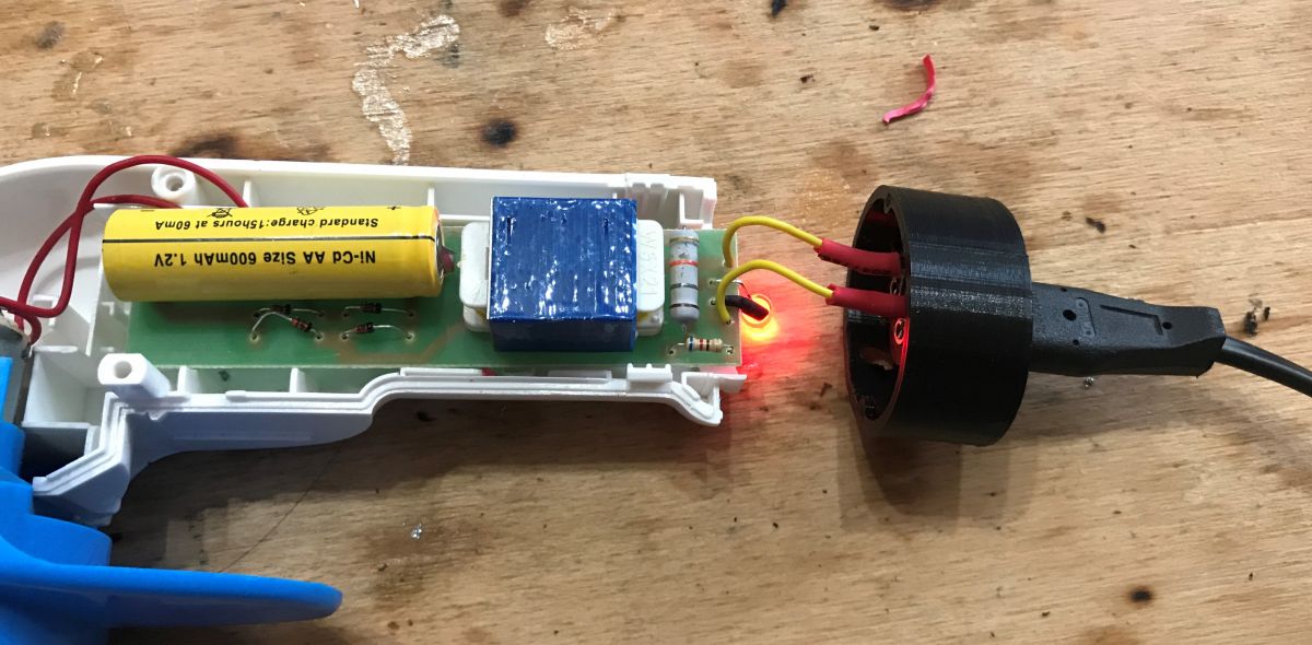
Finished:
Ultimately, I still wanted to round off the corners and print the component in white, but the new owner of the machine decided that this was unnecessary, so I just final glued the connector to the component (so that when the plug is pressed in, it doesn't fall inside the housing).
Summary
The project essentially cost nothing, and even if you counted the weight of the filament it would come out to 7 grams per final piece, so in total with prototypes maybe 25g, at PLN50/kilo that's PLN1.25.... as you can see, it was worth it to save a decomposed machine where a new one costs 35PLN. 3D printing once again showed its usefulness.
After replacing the connector, the razor is compatible with a typical "doubles" power cable, such as many radios, power supplies, or there even Mac OSX mini's have.
I think it's worth saving even such unusual gadgets and 3D printing helps considerably in this. Now I'm still queuing up to replace the electronics inside so that I can charge from USB (probably when the NiCd dies), but that's not likely to happen soon....

p.kaczmarek2 wrote 14408 posts with
rating 12345 , helped 650 times.
Been with us since 2014 year.
Comments
Personally I wouldn't save the Ni-Cd supply and put in a Li-ion cell with a TP4056 board (the motor should be able to withstand the higher voltage). [Read more]
TP4056, what a small world, I recently rescued a screwdriver like this, I like these modules: https://obrazki.elektroda.pl/5698566200_1636301644_thumb.jpg https://obrazki.elektroda.pl/3846952800_1636301653_thumb.jpg... [Read more]
If a device has a battery of three nickel cadmium or nickel hydride batteries connected in series, such a battery can be replaced by a single lithium ion battery or a battery of batteries connected in... [Read more]
You have nicely demonstrated the workmanship of the new housing component. As for the power supply, leave it as it is until it dies of amen. [Read more]
I replaced the motor in a similar shaver. The commutator of poor quality (only plates without carbides) was damaged. [Read more]
Minor correction - from the pictures of the case I take it that these were more like screws. [Read more]