







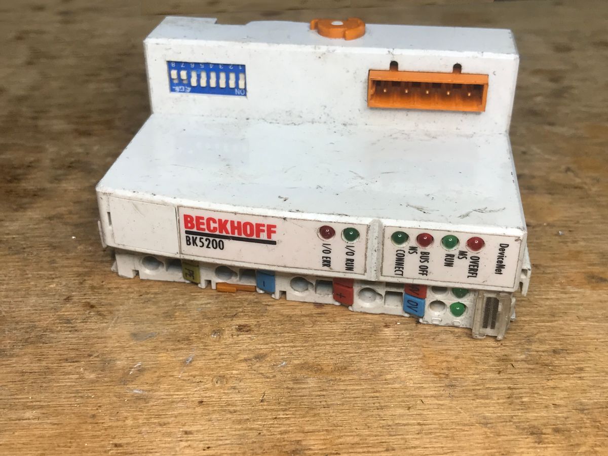
Today we’re taking a look inside a piece of industrial automation equipment. The BK5200, manufactured by Beckhoff, is a so-called DeviceNet® Bus Coupler and is used to connect modular input/output (I/O) terminals to the main communication bus. DeviceNet® is a protocol based on the tried-and-tested CAN physical layer; it is used in machine control systems and enables reliable data exchange between PLCs and remote sensors or actuators.
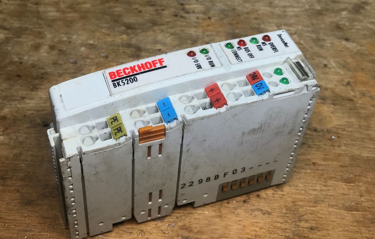
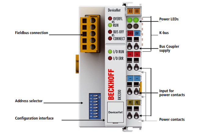
On the front of the unit, there is a block of six LEDs indicating operating status and any errors (these are diagnostic LEDs: I/O RUN, I/O ERR for the internal bus, and statuses for the DeviceNet network), a five-pin DeviceNet bus connector, and an 8-position DIP switch concealed behind a flap, used to set the network address (MAC ID) and baud rate (baud rate).
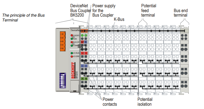
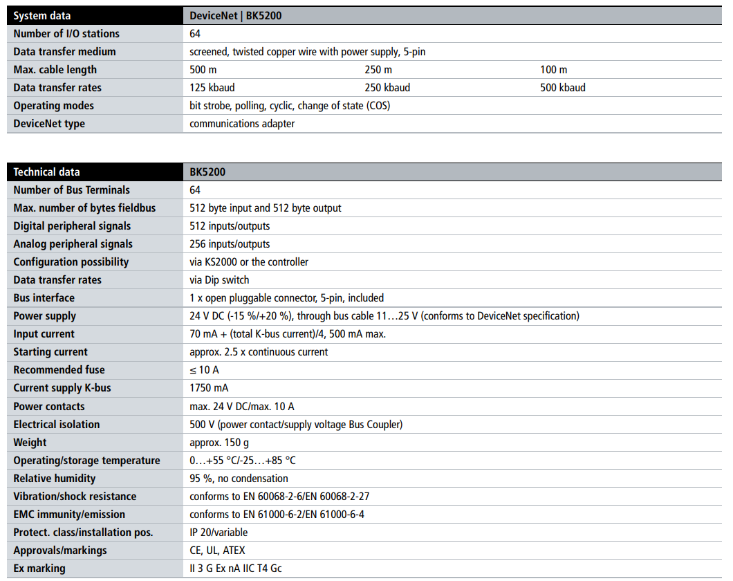
The module supports up to 64 terminals connected via K-Bus, as shown in the diagram from the documentation:
I will attach the full manual in PDF format at the end of this thread.
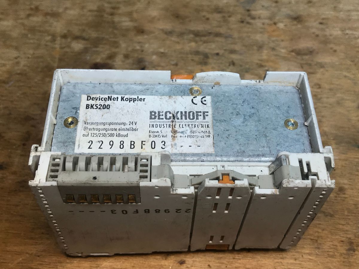
On the rear, there is a rating plate showing, amongst other things, the required supply voltage (24 V), the supported baud rates (125/250/500 kBaud), the exact model (BK5200) and the manufacturer’s details (Beckhoff Industrie Elektronik).
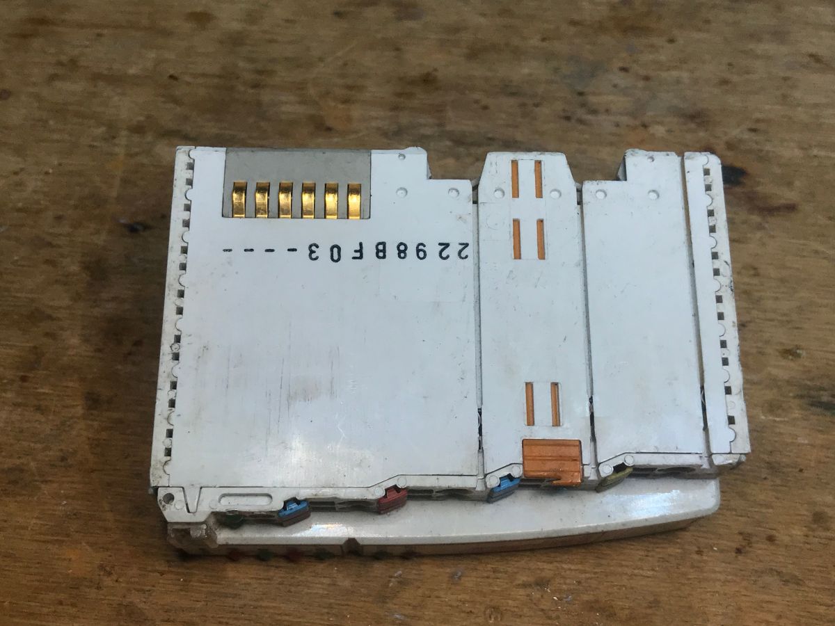
The contacts visible on the right-hand side in the photograph form the internal K-Bus interface (six gold-plated pads), through which the device communicates with the connected input/output modules. Spring-loaded contacts for supplying power to the modules are also visible.
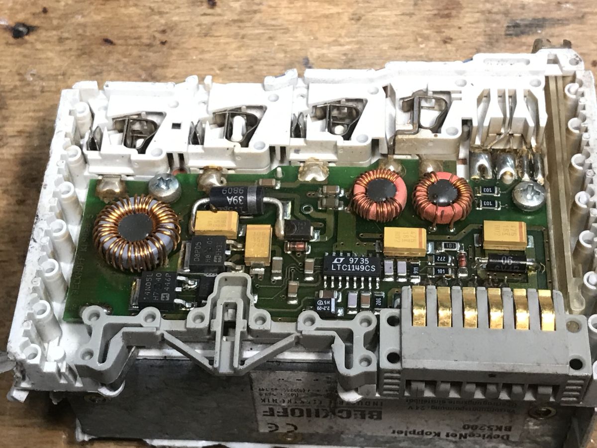
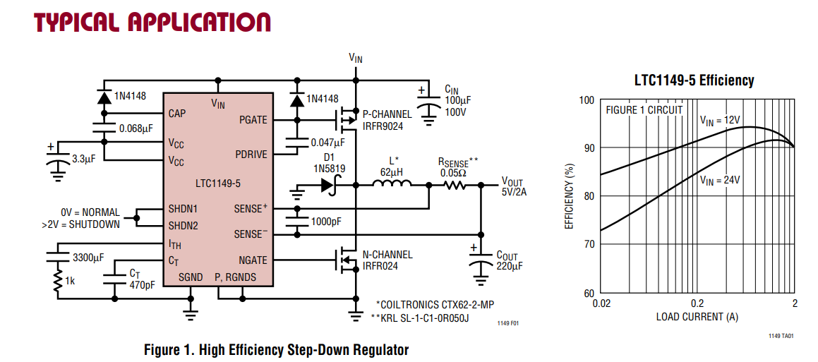
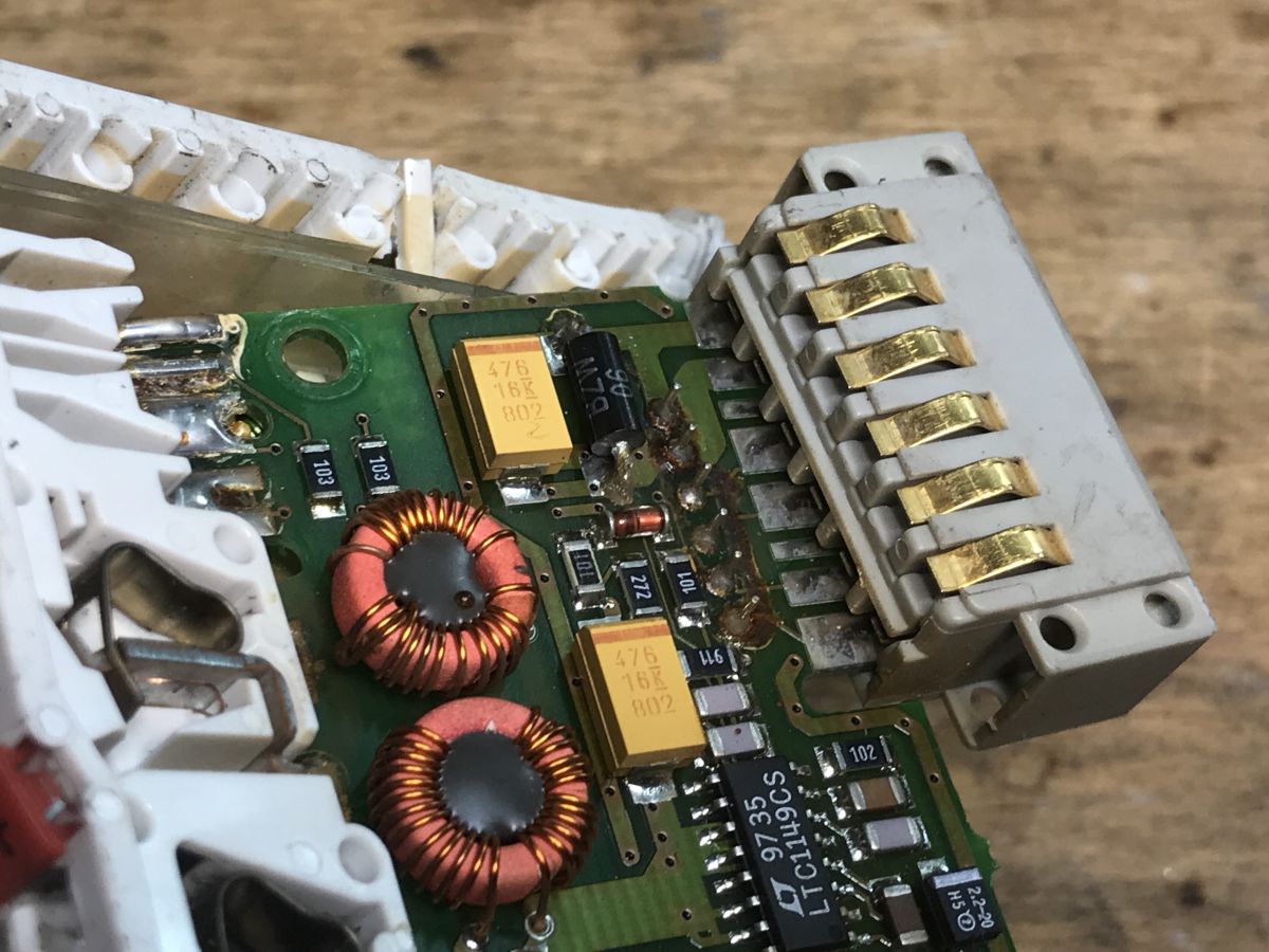
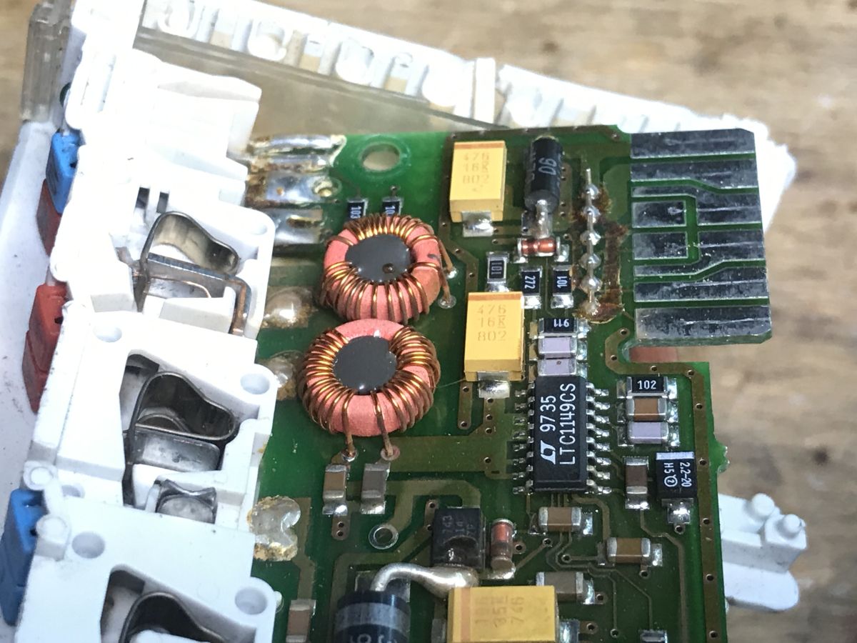
Now let’s take a look inside. The first thing that catches the eye is the power supply section (a multi-voltage switching regulator), with the LTC1149CS chip visible in the centre (a high-efficiency step-down converter controller from Linear Technology) and the characteristic three toroidal chokes and yellow tantalum capacitors.
Dismantling the power supply section:
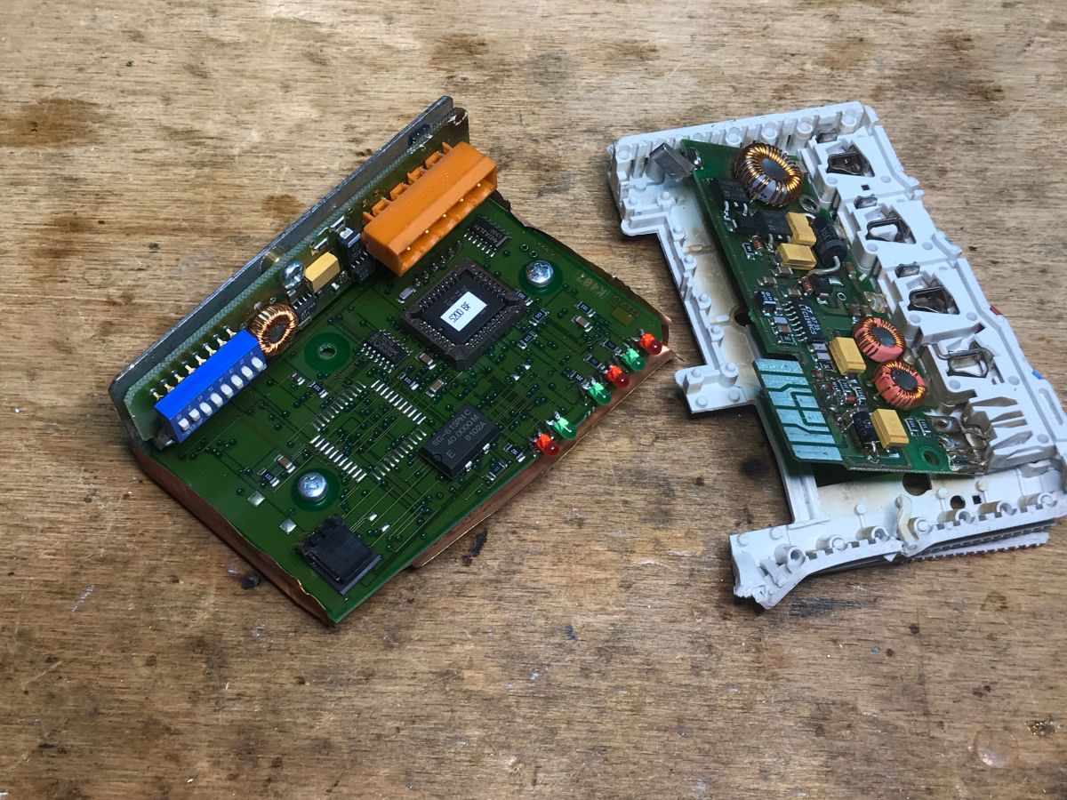
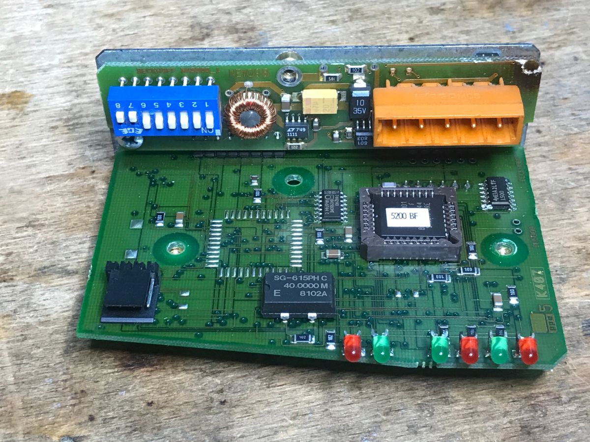
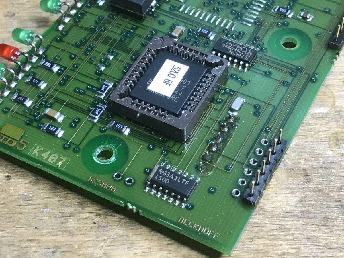
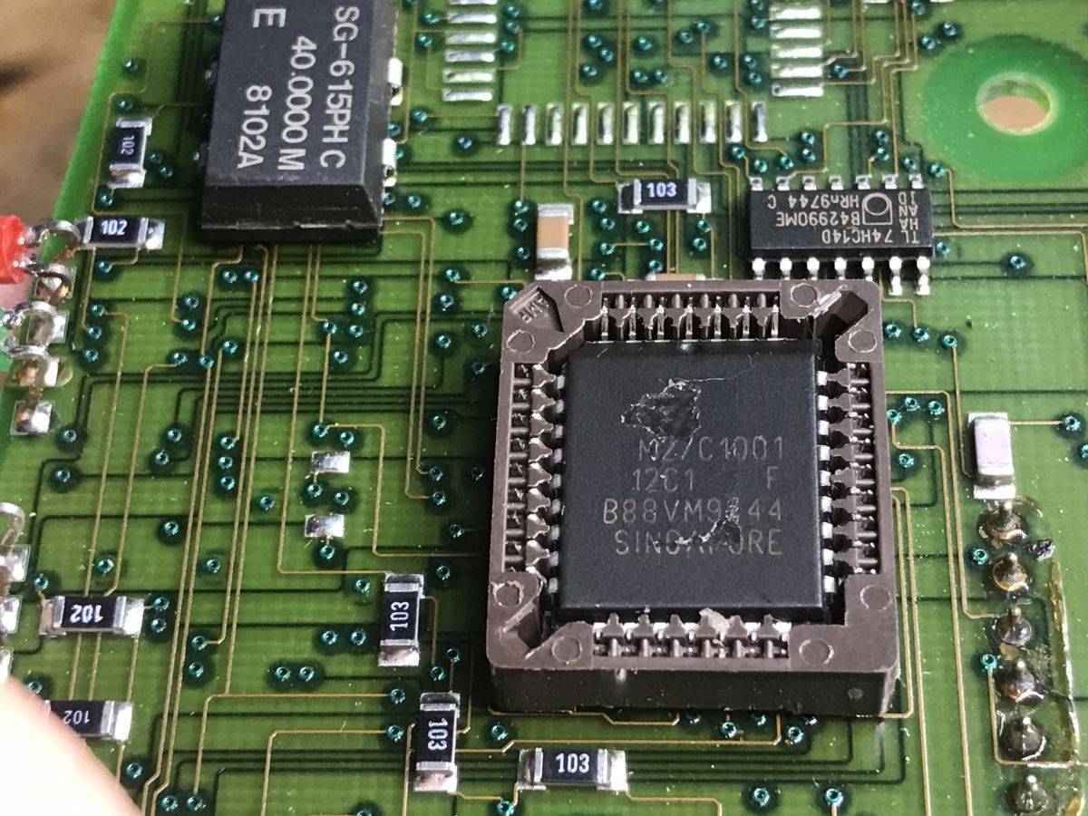
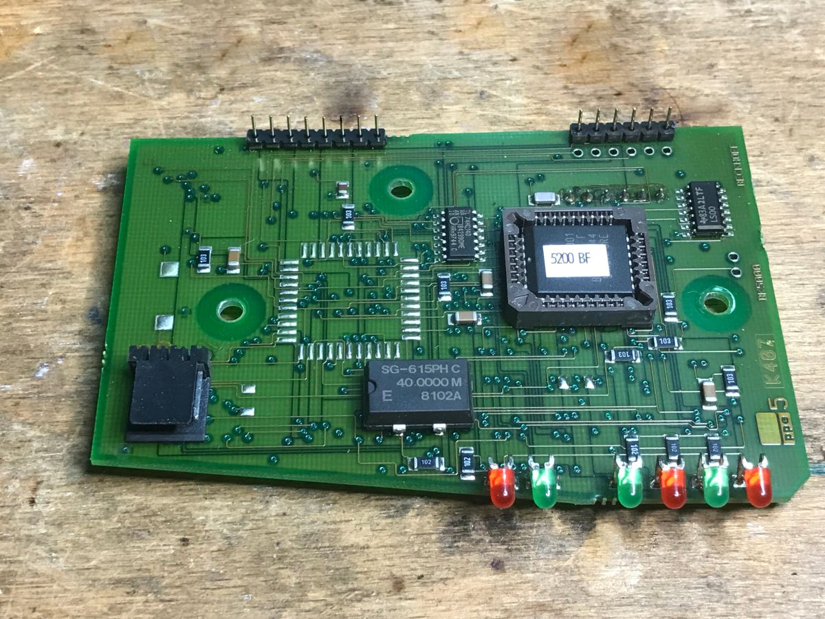
This brings us to the second board, namely the main (logic) board. On it, you can see a large memory chip with a ‘5200 BF’ label – could this be the firmware? – an Epson SG-615PH (40 MHz) and standard logic chips, such as 74HC14D inverters and SN74LS00 NAND gates. The absence of a large processor on this side of the PCB suggests that the circuit’s main microcontroller is located on the underside.
We continue to dismantle the converters:
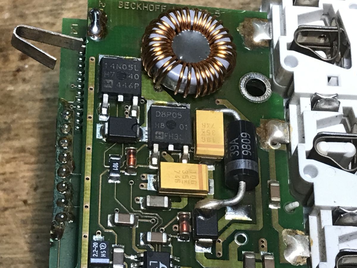
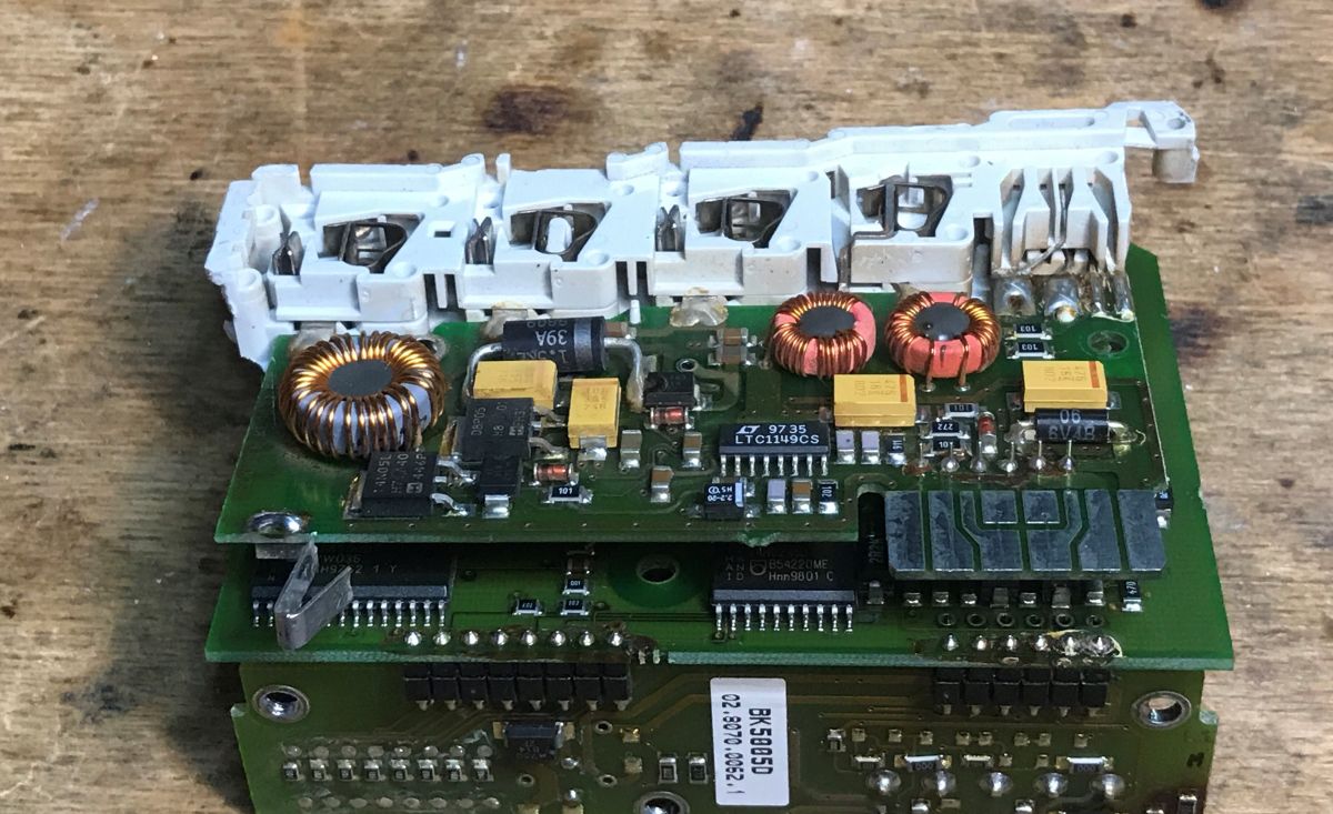
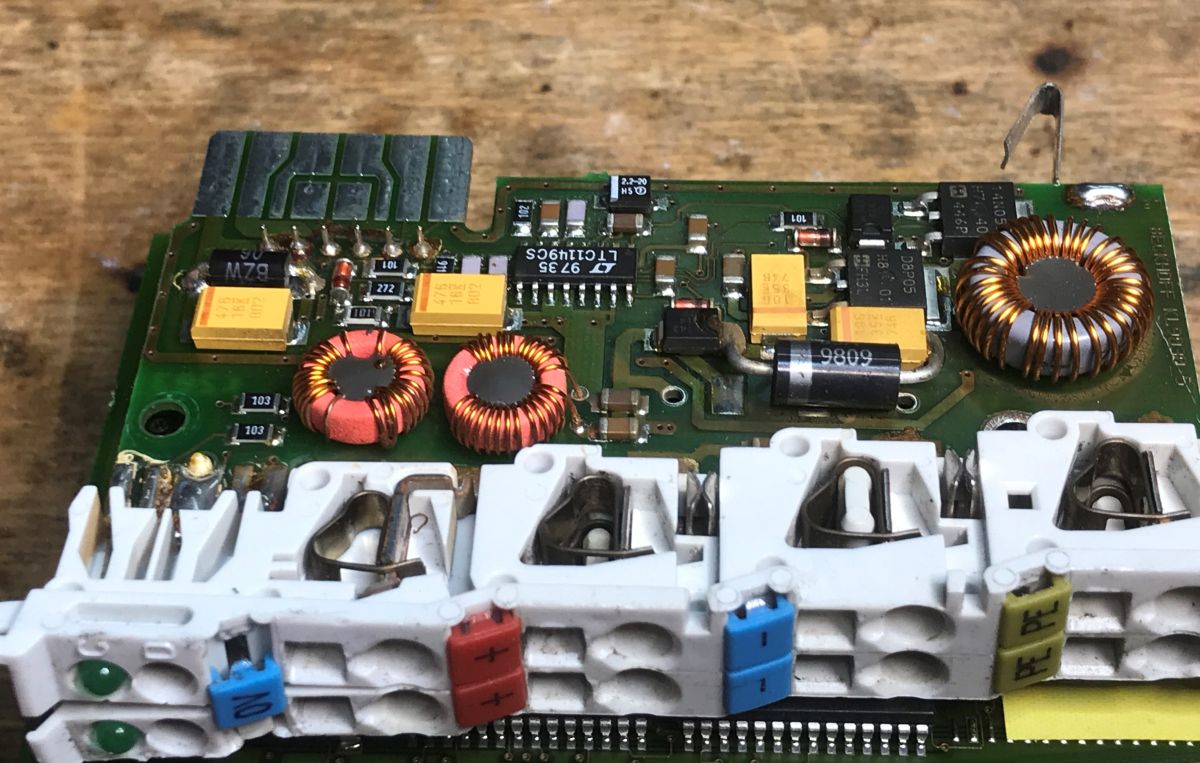
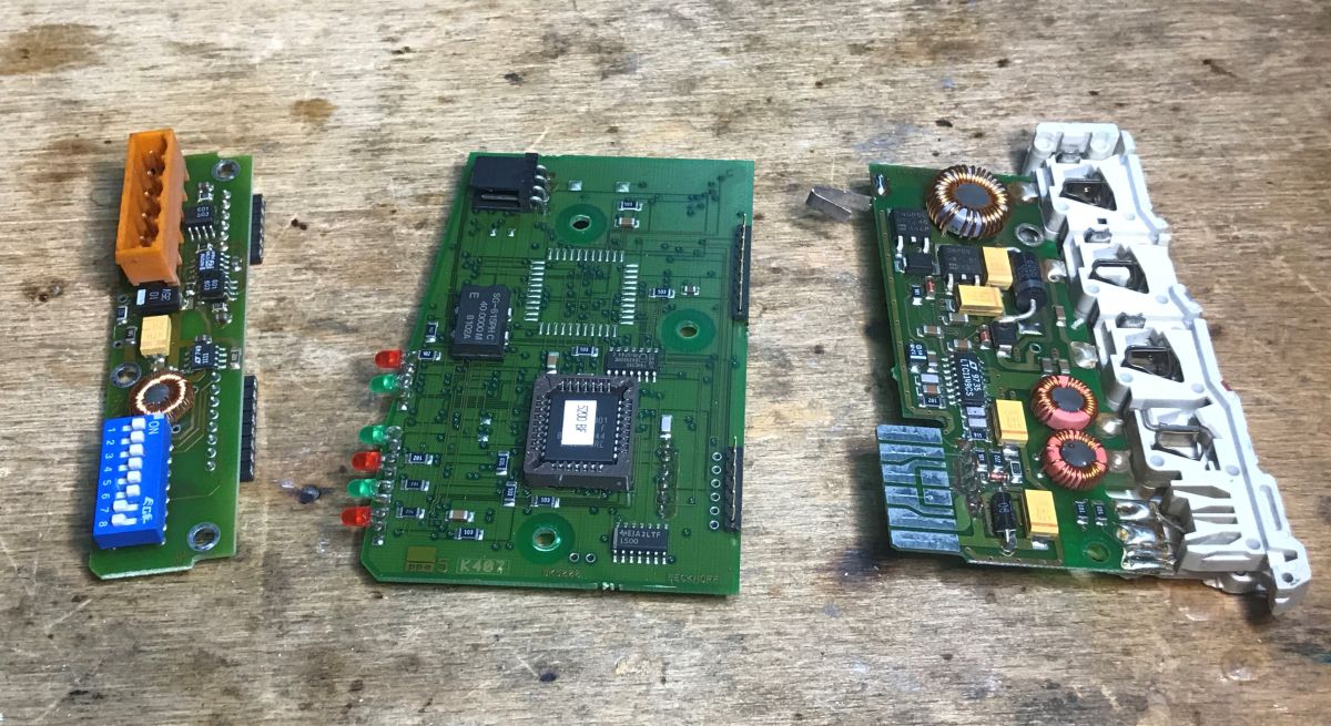
It turns out there are three PCBs inside:
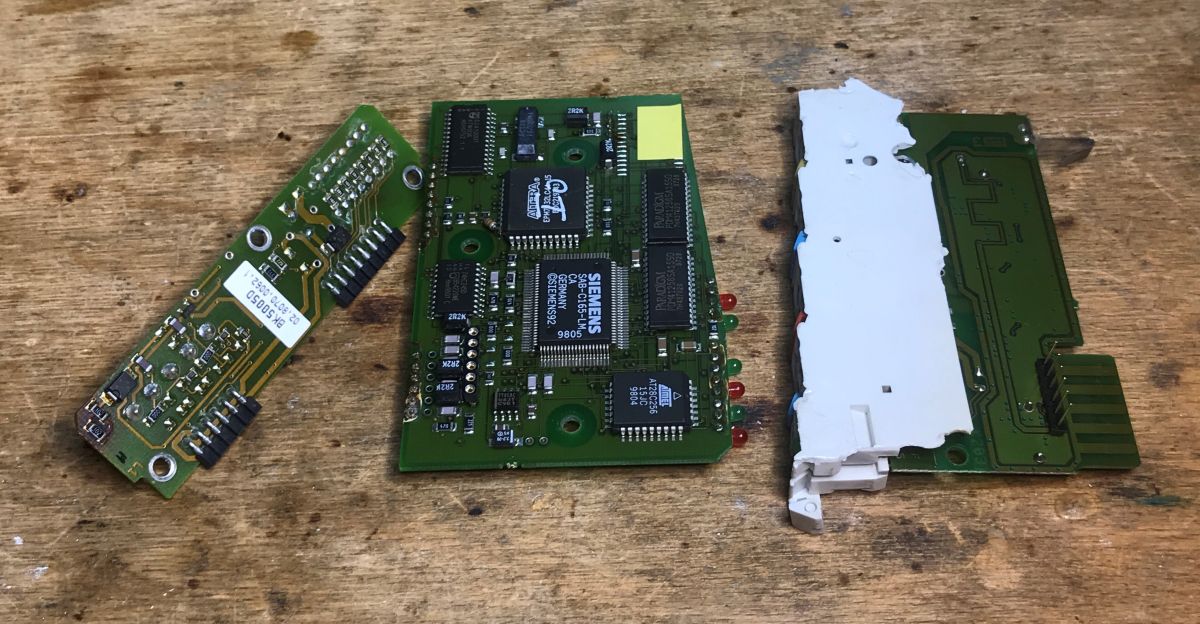
This reveals the actual ‘logic’ board, densely covered with various surface-mounted integrated circuits:
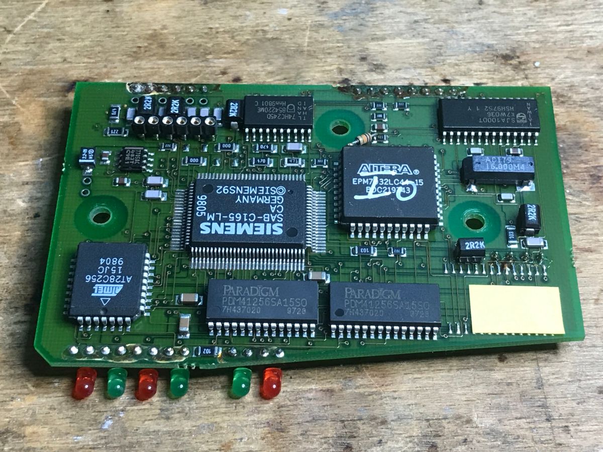
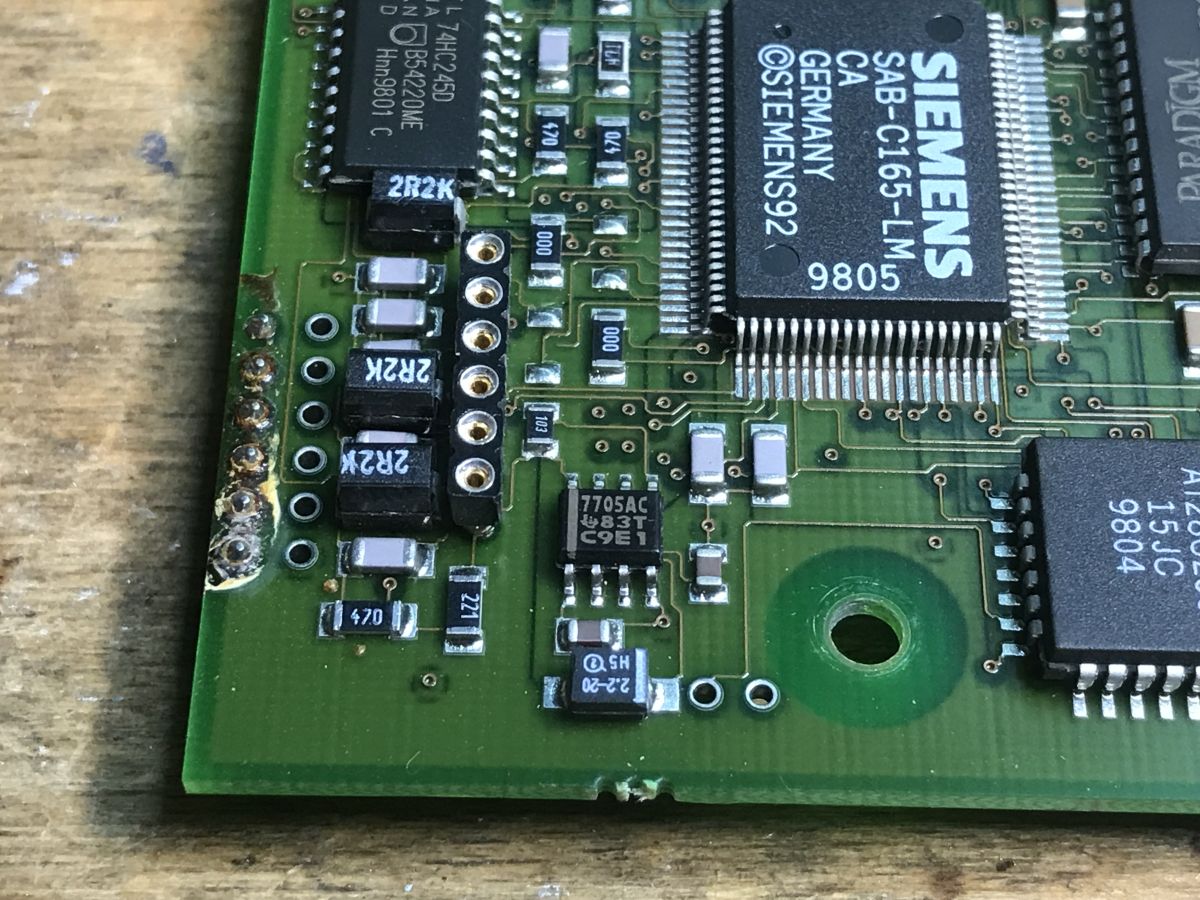
Here we can see the true heart of the entire device. Taking centre stage is the 16-bit Siemens SAB-C165-LM microcontroller (a ROM-less processor based on the high-performance C166 architecture). It communicates via an extensive bus with a dedicated CAN controller – the SJA1000T chip from Philips (NXP), equipped with its own 16 MHz resonator (a classic choice for hardware-based DeviceNet support). We can also see here two Paradigm PDM41256SA15SO SRAM chips (each with a capacity of 32 KB, giving a total RAM capacity of 64 KB for working memory) and an Atmel AT28C256 EEPROM (with a capacity of 32 KB), in which the device most likely stores its non-volatile configuration. All the chips on the bus are linked together by a CPLD from the MAX family – the Altera EPM7032LC44-15.
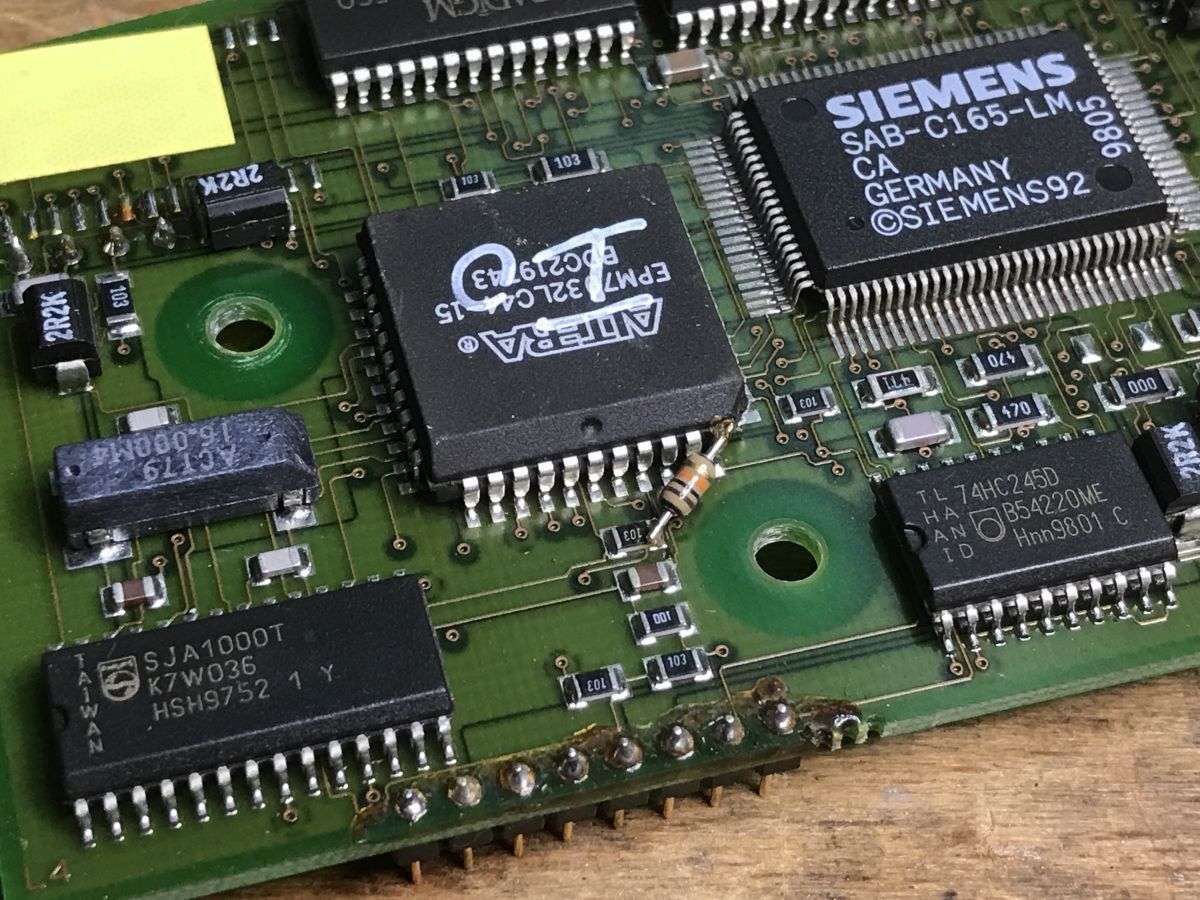
Interestingly, the device must have been through a lot, as we can see a truly ‘hacker-style’ modification here, with a through-hole resistor soldered onto the surface of the Altera chip’s pin. I wonder whether someone repaired it, or whether this is actually a factory fix following a batch that left production with a fault.
There is also a small board with side contacts, marked with the symbol BK5005D:
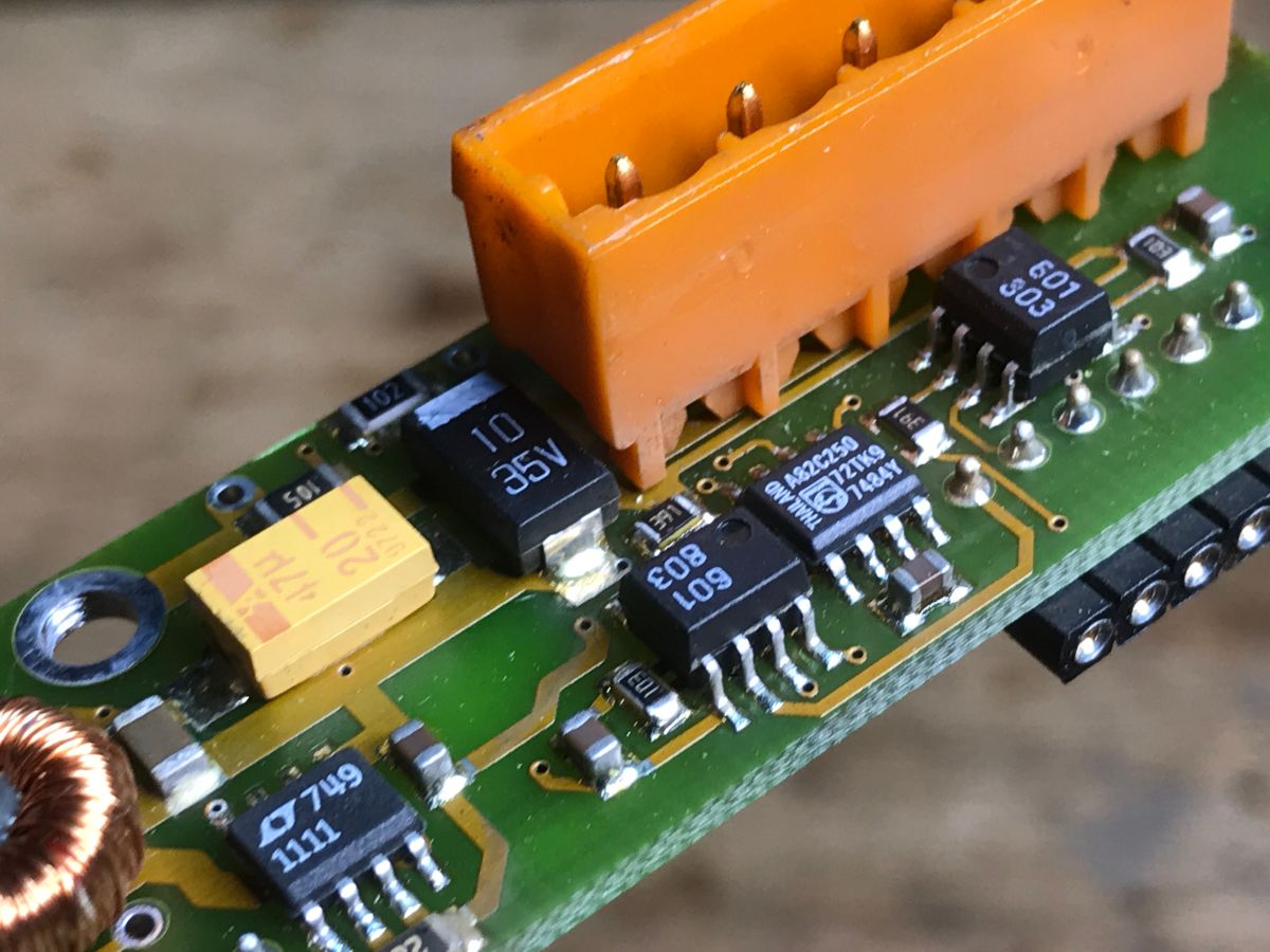
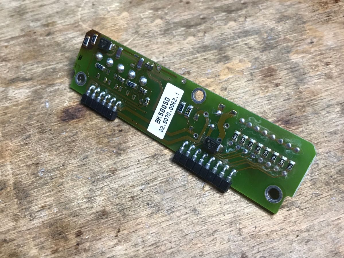
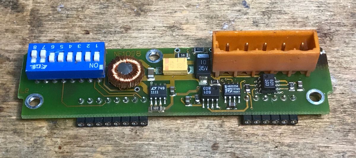
It turns out that this small board is not only a physical interface for plugging in K-Bus modules, but above all a complete interface for the external DeviceNet bus. On the reverse side, there is a 5-pin orange Fieldbus connector and an 8-position DIP switch (accessible from the front panel of the enclosure). Communication with the outside world is provided by a Philips PCA82C250 CAN transceiver, whilst a dedicated circuit ensures full galvanic isolation of the network: high-speed HCPL-0601 optocouplers (labelled ‘601’) for signal isolation and a low-power DC/DC converter based on the Linear Technology LT1111 chip, working in conjunction with a dedicated choke. This module plugs into the main logic board at right angles.
In summary, the Beckhoff BK5200 bus coupler is a device based on a 16-bit Siemens microcontroller (C166 family) working in conjunction with an Altera CPLD logic chip. The hardware resources are supplemented by a Flash memory module in a socket (presumably for firmware), 64 KB of SRAM and 32 KB of non-volatile EEPROM for configuration. The power supply section is based on a switching converter using a Linear Technology chip, whilst DeviceNet communication is handled by a Philips CAN controller supported by a galvanic opto-isolator.
Have you worked with modules of this type? How would you rate their reliability, and what do you consider to be their strengths and weaknesses?
Cool? Ranking DIY Helpful post? Buy me a coffee.

