[BK7231N ] Teardown of TH08 LCD Calendar/clock/temperature/humidity, 3xAAA battery, backlight
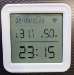
Hello all,
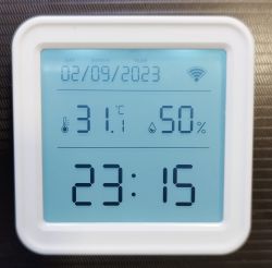
After searching the database, I think this is the first post for this device. It seems to be a newer version of others already described here. I like the display design, also with backlighting, and that it is battery powered (3xAAA - 4.5V, probably easy to convert to LiPo).
Aliexpress's link: https://www.aliexpress.com/item/1005005644804864.html
Aliexpress' ad capture (in case link becomes obsolete):
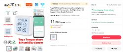
It's advertised for 11,79€ with free shipping, but I managed to get it for 4,49€ as a "Choice" offer:

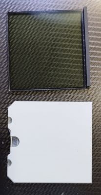
External and teardown photos:

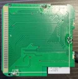
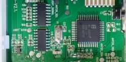
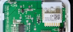
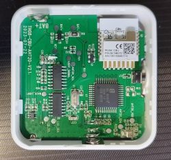
As you can see, the PCB silkscreen states "TH08-CBU-ATH20-V2 2023/07/22"
I understand:
- "TH08" is the model so it must be a newer version of TH06, covered here and here. It could be also a close relative of the item described here
- "CBU" refers to the WiFi module, as it corresponds with the module's silkscreen (datasheet)
- "ATH20" is the temperature/humidity sensor (product page and datasheet)
There are also:
- A big IC labelled "BL 55070", which is an LCD driver (product page and datasheet)
- Two 16 pin ICs with the label erased: One of them (U8) has a quartz crystal connected (X1), and three pins are connected to pads labeled "BACK_LIGHT", "LCD_SDA" and "LCD_SCL", so it's clear it controls the display and its backlight, so I think this is a dedicated RTC. Some tracks connect this IC with the previous one (U3), which in turn has pins connected to pads labeled "RX1" and "TX1" (connected to the Wifi Module), "ATH20SDA" (sensor) and "LIGHT_SIGNAL", connected to U8. This one must be the Tuya MCU.
Among the other components, Q1 controls power to the WiFi module, similar to the other products mentioned above. It's an N-Channel Enhancement Mode MOSFET NP2302FVR-J (datasheet).
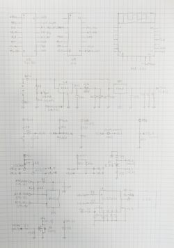
The full schematic and block diagram are included below and the analysis of traffic in RX1 and TX1 will be posted later (done, see post#33)
Tuya App screenshots:
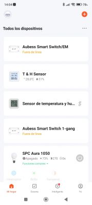
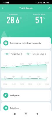
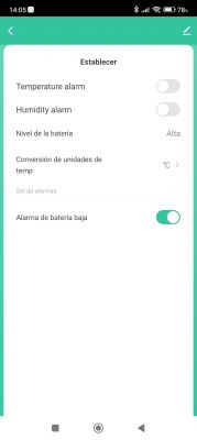
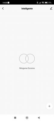
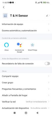
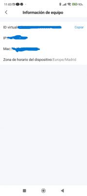
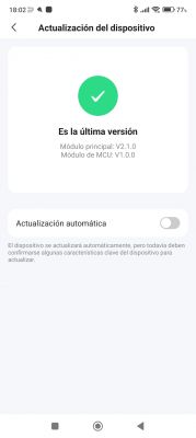
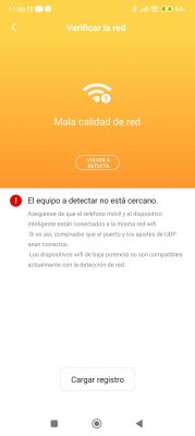
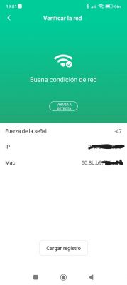
The update interval for the graphics is very long (1 hour) and, apparently, can't be changed from the app (its an App related issue; the device updates more frequently, as you can see later in this thread). Related to this, the last screenshot shows an error when trying to connect to the device. I understand it's because the device only connects for a brief time between updates, so you should connect to it in that brief moment to get the info (I've tried just after inserting the batteries without success, so it must be the connection doesn't last enough). After powering the module directly to be able to read it with BK7231flasher, I could complete this screen, so it's attached after the one with the error.
Schematic:
Block Diagram:
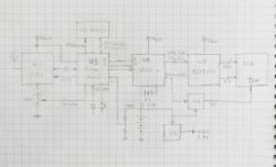
After drawing this, it seems clear U3 is the main MCU, connected to CBU module via RX1 and TX1, to the key, to the sensor via I2C, to the LED, to a voltage divider from the battery, and to the other U8 with two wires (another I2C or RX-TX?) and another signal to start the backlight. There's also a mysterious pad (PB5) connected to it.
U8, with a 32.768 kHz oscillator, is probably an RTC, controls the LCD via I2C to U1 and also the duration of the backlight, and is programmed/read by U3 via a two-wire interface.
As stated above, Q1 is a mosfet controlling power to the WiFi module, switching on or off the connection to ground.
Finally, U4 is the main voltage regulator (2,8 volts) feeding all components except the backlight, which is fed by U6 (3 volts) that is turned on or off by pin 9 of the RTC.
NOTE: I've updated several times this post to include the information that we have been finding along the thread. Still pending to include the summary of the OBK flashing procedure and its configuration


Comments
This indeed looks like a new version of TH06, just as you said. Let me know when you've done the packets capture. I wonder how much of the protocol/dpIDs has changed. [Read more]
Hi, I just happened to unpack, disassemble and flash the same device today! I was about to create a post for it, but then you have been already doing this job, thank you! Maybe we can work together to... [Read more]
OpenBeken sends time only when it's requested: https://obrazki.elektroda.pl/9594592300_1694037873_thumb.jpg I can't see : TuyaMCU_ProcessIncoming: received TUYA_CMD_SET_TIME, so sending back... [Read more]
Yes, indeed, it would be good to find out how time is transferred from firmware to the module... is it requested? Or pushed through without request? How can we find out, is there anything I can contribute... [Read more]
It's just accident. Those are not related. It seems that 0x10 (decimal 16) is ObtainDPCache: https://obrazki.elektroda.pl/6885502900_1694066322_thumb.jpg Here are the docs: https://developer.tuya.com/en/docs/iot/tuyacloudlowpoweruniversalserialaccessprotocol?id=K95afs9h4tjjh Interestingly... [Read more]
Sweet! Thanks for your efforts! I'll test the updated version as soon as its possible and post results, let's see if there is a response. [Read more]
Hello again, I've just updated the first post with some corrections and more information (schematic), and I see you've been making making progress!! Time to read them in detail and see if I can add... [Read more]
The display is controlled via MCU, that's why it's hard to just remove MCU and do everything in OpenBeken, although IMHO it would be the preferred way. TuyaMCU complicates lots of things. [Read more]
Good news! It works with the new version! Good job, thank you so much! Look at the beautifully working sensor now: https://obrazki.elektroda.pl/5404196700_1694084370_thumb.jpg And here we... [Read more]
Whoa, I didn't expect it to work at the first try! I haven't even compiled that code before pushing it. Well, if everything really works as expected, then there is very little point to doing data capture.... [Read more]
Congratulations!! I'll also give it a try. As you haven't changed anything in this sense, I imagine the report time is still one hour, which I find too long. In the Tuya App there's no option to reduce... [Read more]
Polling time setting may be done via dpCache (ObtainDPCache), but you need to know the corresponding dpID. See this topic for example usage: https://www.elektroda.com/rtvforum/topic3975583.html If... [Read more]
Hello, p.kaczmarek2. I posted it here following the instructions here . Is it correct? Should I also post something (e.g, a link to this thread) also in the general Devices Teardown forum? [Read more]
I checked Home Assistant history and I get an update of sensor data every ~17 minutes as standard, even without change of temperature or humidty. As soon as there is a change in temperature or humidity,... [Read more]
Ok, sorry to hear that. Anyway, I'm not sure if "polling time" was the correct term for my question, what I meant is if there was a command to set the period in which the MCU "wakes up" the CBU WiFi module... [Read more]
Generic teardowns section is only for non-iot teardowns, and smart home is for IoT topics and teardowns. As I said, check if there is an option to set that wake up period in Tuya app, and if it's available,... [Read more]
Ok, thanks!, I'll try that and report back. I think, apart from the original firmware's low reporting frequency, this version of the device has one of the best designs and, if the battery life is long... [Read more]
haha, I have played with thought about Lipo-mod as well! And we could squeeze in a USB-charge module, but we would need to cut the battery plastic housing to make some space. Else I totally agree, I think... [Read more]
I already checked it, as you can see in the screenshots at the first post, it seems that option is not available, unfortunately. Totally agree... such an effort is not worth it, and probably this... [Read more]