Elektroda.com
Elektroda.com
X

Teardown of the TH06 clock/thermometer/hygrometer and UART reverse engineering

p.kaczmarek2 9318 18
This content has been translated flag-pl » flag-en View the original version here.
  • Teardown of the TH06 clock/thermometer/hygrometer and UART reverse engineering
    Hello.
    Here I will present a quick test and teardown of the Tuya TH06 LCD clock/thermometer/hygrometer powered by USB. I will briefly explain how to pair with the phone, show the functionality of the mobile application, and then I will proceed to tear down part, and last, but not least, I will describe the reverse engineering process of its UART communication protocol. The UART protocol turns out to be not human-readable because it's binary, but I will explain how to handle that and extract information about the date and time.

    Purchase of a TH06 calendar / thermometer / hygrometer
    This product is available in many stores, including on Alie ~, but I bought it myself on a slightly different website for about 20$ - PLN 80:

    Teardown of the TH06 clock/thermometer/hygrometer and UART reverse engineering
    Offer name (use this to search for this product):
    Tuya WIFI Temperature Humidity Smart Sensor Clock Digital Display Remote Control Thermometer Support Alexa Google Assistant - Type A
    It can also be easily found under the entry "TH06":

    Teardown of the TH06 clock/thermometer/hygrometer and UART reverse engineering
    Parameters according to the seller:
    Quote:

    ABS material
    Power Supply
    DC 5V / 1A
    Wi-Fi Support
    2.4G IEEE 802.11 b / g / n
    Temperature Measure Range
    0 ? -60 ?
    Temperature Accuracy
    ? 1 Humidity
    Measure Range
    0% RH ~ 99% RH
    Humidity Accuracy
    ? 1% RH
    Weight 45.8g
    Size 65 * 65 * 17mm / 2.5 * 2.5 * 0.6in

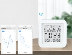
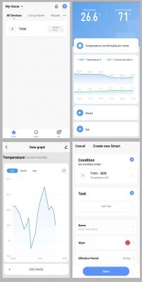
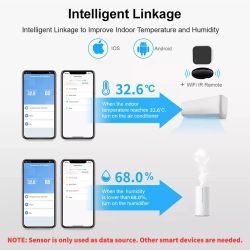
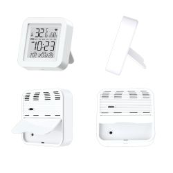
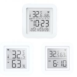
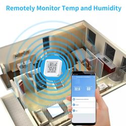
    Promotional graphics illustrate its operation (and information that it provides in the phone application):
    Teardown of the TH06 clock/thermometer/hygrometer and UART reverse engineering
    Teardown of the TH06 clock/thermometer/hygrometer and UART reverse engineering
    Teardown of the TH06 clock/thermometer/hygrometer and UART reverse engineering Teardown of the TH06 clock/thermometer/hygrometer and UART reverse engineering
    Teardown of the TH06 clock/thermometer/hygrometer and UART reverse engineering Teardown of the TH06 clock/thermometer/hygrometer and UART reverse engineering
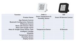
    Sellers emphasize that the product is available in two versions. The second, black version, additionally supports IR control and is called S09:
    Teardown of the TH06 clock/thermometer/hygrometer and UART reverse engineering


    Related Topics
    I have already written a few topics about WiFi products based on ESP (or similar systems). I mainly do teardowns there.
    I also describe the process of programming such a switch and using it with the manufacturer's application (Blitzwolf, SmartLife, Tuya, eWeLink) or Tasmota.
    I recommend that you familiarize yourself with these topics, I will not repeat all the information several times and as a rule, they apply to all products of this type.
    (Warning: not all of those topics are translated to English right now but I am working on it)
    List below:
    - BW-LT30 or adapterWiFi on bulb - test, teardown and uploading ESP firmware
    - WiFi-controlled electrical socket - BW-SHP8 - start-up and tests
    - Test and interior of the BW-SS3, i.e. the WiFi light switch from Blitzwolf
    - PS-16-M WiFi socket / plug and eWeLink / Coolkit application - test and teardown
    - SmartLife switch - test, interior and WiFi light switch programming (similar switch, but without RF and description of programming it in Arduino via cables)
    - SC3-01 SmartLife switch and uploading ESP firmware via WIFI (tuya-convert / OTA) (this time programming via WiFi, no need to open the housing, no soldering of cables)
    - WiFi QTouch switch plugged into the L cable only - test, interior, diagram (an interesting switch, which is implemented on the thyristor, not on the relay, but also has ESP8285 inside)
    - WiFi SmartLife single-color LED strip dimmer - test, interior, diagram (interesting LED strip driver on MOSFET and WB3S transistor)
    - SmartSwitch Tuya WL-SW01_16 16A WiFi - test, interior (WB2S)
    - WiFi door / window opening sensor - test, interior, integration with other devices Search in topic (sensor based on the XR809 / XR2 module)
    - Proprietary open firmware for XR809 compatible with Tasmota HTTP / Home Assistant (a detailed description of how to create your own batch for the door sensor on the XR809)
    Additionally, the topic about Tasmota and the DIY version of the WiFi relay:
    - ESP8266 and Tasmota - step-by-step control of the WiFi relay
    Additionally, I recommend my topic about Home Assistant (which can control a collection of such devices):
    Home Assistant Tutorial - configuration, WiFi, MQTT, Zigbee, Tasmota

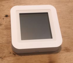
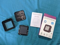
    Kit contents, first impression
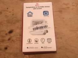
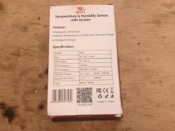
    The set came in a flat box:
    Teardown of the TH06 clock/thermometer/hygrometer and UART reverse engineering Teardown of the TH06 clock/thermometer/hygrometer and UART reverse engineering Teardown of the TH06 clock/thermometer/hygrometer and UART reverse engineering
    Product code: SKUH77374
    The product model (TH06) is also printed on the packaging.
    Contents (USB cable is included, but it's a power-only cord, without Data lines):
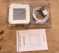
    Teardown of the TH06 clock/thermometer/hygrometer and UART reverse engineering
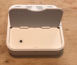
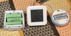
    There is a micro USB connector on the back, device has no batteries, it must be constantly connected to USB 5V in order to work. This flap is just a leg:
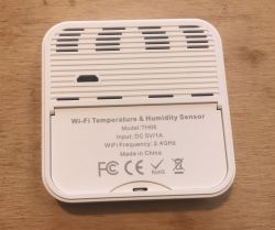
    Teardown of the TH06 clock/thermometer/hygrometer and UART reverse engineering Teardown of the TH06 clock/thermometer/hygrometer and UART reverse engineering
    There is also a RESET button:
    Teardown of the TH06 clock/thermometer/hygrometer and UART reverse engineering
    The product does not remember the date / time after it is turned off. The current time is taken by the WiFi network from Web. It needs to be paired beforehand, so you need to use your phone and the SmartLife application.
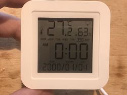
    Teardown of the TH06 clock/thermometer/hygrometer and UART reverse engineering
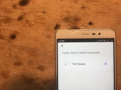
    Pairing is very simple, I have already covered it many times in this series. According to the instructions, we press RESET longer, we provide information about our WiFi in the app ...:
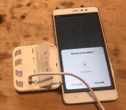
    Teardown of the TH06 clock/thermometer/hygrometer and UART reverse engineering Teardown of the TH06 clock/thermometer/hygrometer and UART reverse engineering
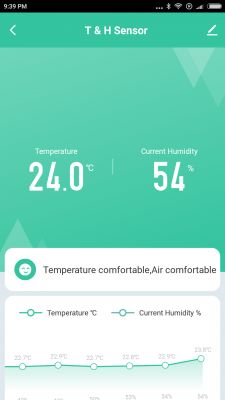
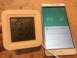
    Added (the temperature shows high, because I heated it with a lamp to check the reaction time - it is quite fast):
    Teardown of the TH06 clock/thermometer/hygrometer and UART reverse engineering

    Android application and its possibilities
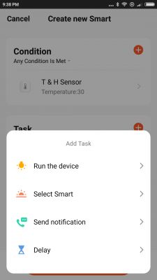
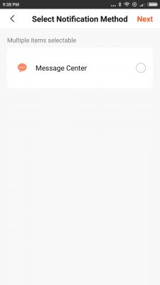
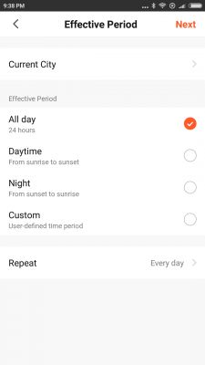
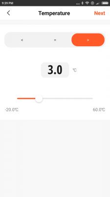
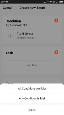
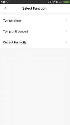
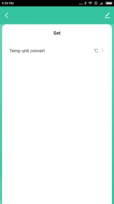
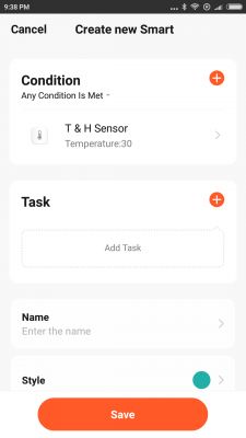
    I have already described it several times, so here I just emphasize that the application offers a really wide range of possibilities for creating automation and work scenarios. We can trigger events with temperature, humidity, and even (I don't know why) by changing the format of the displayed temperature (F or C). We can condition events with the current time of the day, with the states of other devices, etc.
    We have AND and OR logical operations available, we have delays.
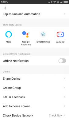
    Below is a collection of application screenshots:
    Teardown of the TH06 clock/thermometer/hygrometer and UART reverse engineering Teardown of the TH06 clock/thermometer/hygrometer and UART reverse engineering
    Teardown of the TH06 clock/thermometer/hygrometer and UART reverse engineering Teardown of the TH06 clock/thermometer/hygrometer and UART reverse engineering
    Teardown of the TH06 clock/thermometer/hygrometer and UART reverse engineering Teardown of the TH06 clock/thermometer/hygrometer and UART reverse engineering
    Teardown of the TH06 clock/thermometer/hygrometer and UART reverse engineering Teardown of the TH06 clock/thermometer/hygrometer and UART reverse engineering
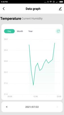
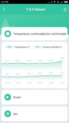
    Also, of course, there is history and charts:
    Teardown of the TH06 clock/thermometer/hygrometer and UART reverse engineering Teardown of the TH06 clock/thermometer/hygrometer and UART reverse engineering
    Teardown of the TH06 clock/thermometer/hygrometer and UART reverse engineering Teardown of the TH06 clock/thermometer/hygrometer and UART reverse engineering

    Power consumption from USB
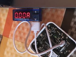
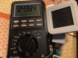
    The display current consumption is not high. USB Doctor was unable to record it at all:
    Teardown of the TH06 clock/thermometer/hygrometer and UART reverse engineering
    For this reason, I measured it with a multimeter. During operation (after downloading the date from the Internet) it fluctuates between 20mA and 30mA:
    Teardown of the TH06 clock/thermometer/hygrometer and UART reverse engineering
    The average output is 0.15W (+ power supply losses).

    Similar product but battery powered
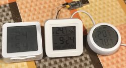
    It is worth noting that if we do not want to display the current date, we have many different options to choose from, they can be easily found under the entry "tuya lcd thermometer" and the like:
    Teardown of the TH06 clock/thermometer/hygrometer and UART reverse engineering Teardown of the TH06 clock/thermometer/hygrometer and UART reverse engineering
    This round one, TS0201 RSH-Z-Bee-HS01, is on the Zigbee, I've already described it:
    https://www.elektroda.pl/rtvforum/topic3806108.html

    Interior of the TH06
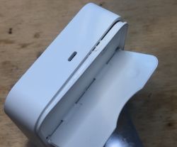
    The housing is latched. It must be undermined:
    Teardown of the TH06 clock/thermometer/hygrometer and UART reverse engineering
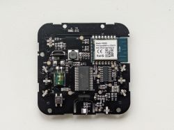
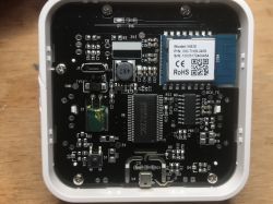
    There is quite a lot of electronics inside:
    Teardown of the TH06 clock/thermometer/hygrometer and UART reverse engineering
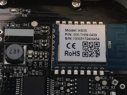
    The heart of the device is the Tuya WB3S WiFi module:
    Teardown of the TH06 clock/thermometer/hygrometer and UART reverse engineering
    Unfortunately, it is not based on ESP. We will not be able to upload Tasmota (although you can convert it to ESP12F, desolder and solder ESP ...)
    The WB3S is based on the 32-bit BK7231T. WB3S offers 1T1R WLAN module, 256-KB SRAM, 2MB flash memory and rich peripherals.
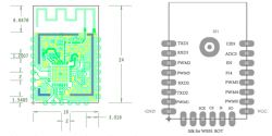
    Teardown of the TH06 clock/thermometer/hygrometer and UART reverse engineering
    However, the WB3S itself does not support this device. Next to it is a chip in SOIC that looks like a microcontroller, but unfortunately is not signed.
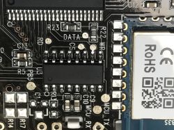
    Teardown of the TH06 clock/thermometer/hygrometer and UART reverse engineering
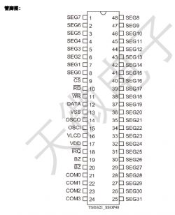
    In addition, we have the LCD driver, TM1621B:
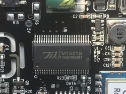
    Teardown of the TH06 clock/thermometer/hygrometer and UART reverse engineering
    The production system of Titan Micro Electronics. It is powered with the voltage of 2.4-5.2V. Here in the SSOP48 housing. Supports a display up to 32 by 4 segments.
    Internal diagram:
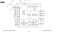
    Teardown of the TH06 clock/thermometer/hygrometer and UART reverse engineering
    Pin Roles:
    Teardown of the TH06 clock/thermometer/hygrometer and UART reverse engineering
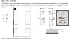
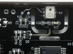
    Of course, there is also a temperature / humidity sensor on the board. This is a very popular AHT10:
    Teardown of the TH06 clock/thermometer/hygrometer and UART reverse engineering
    Communication with AHT10 takes place via I2C:
    Teardown of the TH06 clock/thermometer/hygrometer and UART reverse engineering
    AHT pins:
    Teardown of the TH06 clock/thermometer/hygrometer and UART reverse engineering
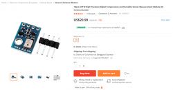
    The AHT10 can also be purchased as a separate module. It can be easily used, for example, with Arduino.
    Teardown of the TH06 clock/thermometer/hygrometer and UART reverse engineering
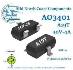
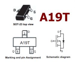
    Next to AHT10 you can see a transistor signed A19T.
    Maybe it's AO3401? I can see it is very popular:
    Teardown of the TH06 clock/thermometer/hygrometer and UART reverse engineering
    Teardown of the TH06 clock/thermometer/hygrometer and UART reverse engineering
    This transistor is probably some part of the AHT10 circuit, I see a similar element on the modules with it.
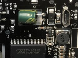
    There is of course also the power section. The characteristic large element marked 4R7 is a choke (not a resistor), it proves that there is a step down converter that converts 5V to 3.3V for the WB3S. There is also no LDO regulator in the vicinity, which also confirms the presence of a step down converter. The step down converter is more efficient than the regulator.
    Teardown of the TH06 clock/thermometer/hygrometer and UART reverse engineering
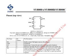
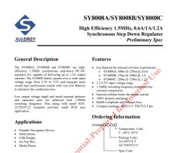
    The step down controller is signed A121.
    It's probably SY8008A / SY8008B / SY8008C. I can see that someone from the Radiokot forum was already looking for it.
    It is a highly efficient, synchronous step down converter:
    Teardown of the TH06 clock/thermometer/hygrometer and UART reverse engineering
    Pinout top view:
    Teardown of the TH06 clock/thermometer/hygrometer and UART reverse engineering
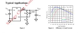
    Sample application and charts showing efficiency:
    Teardown of the TH06 clock/thermometer/hygrometer and UART reverse engineering
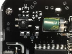
    It is also worth noting that the manufacturer has placed a large low ESR electrolytic capacitor.
    Only the button remains (I do not know what these unpopulated place under Q2, Q3 are for):
    Teardown of the TH06 clock/thermometer/hygrometer and UART reverse engineering
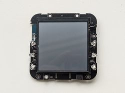
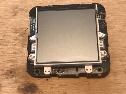
    Now a glance from the front.
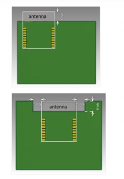
    This protruding part of the WB3S module is not a coincidence. This is where the antenna is on the board. It shouldn't be covered:
    Teardown of the TH06 clock/thermometer/hygrometer and UART reverse engineering
    Tuya strongly recommends not to cover the antenna with a PCB. This would reduce the range / quality of the WiFi signal:
    Teardown of the TH06 clock/thermometer/hygrometer and UART reverse engineering
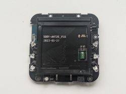
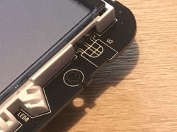
    There is also a place for a mysterious element with three pin, which in my opinion would undoubtedly be an IR receiver:
    Teardown of the TH06 clock/thermometer/hygrometer and UART reverse engineering
    So probably the second version of this product with IR uses the same board, but has an additional receiver soldered here.


    Reverse engineering of the UART protocol with TH06
    Inside we probably have a microcontroller that communicates with WB3S via UART. This is a fairly common solution in this type of product.
    Let's try to get to know their communication protocol.
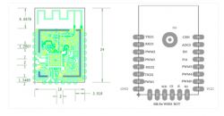
    I started by locating the UART pins. That's not a problem, we have the WB3S documentation:
    Teardown of the TH06 clock/thermometer/hygrometer and UART reverse engineering
    The picture with the leads is a view from the bottom, so looking from above we have to mirror it in our mind.
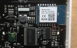
    I also tracked the pins on the board:
    Teardown of the TH06 clock/thermometer/hygrometer and UART reverse engineering
    Both RX and TX go to unknown microcontroller circuits, which is all as expected.
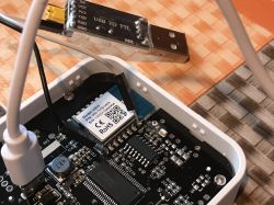
    I soldered the cable to the TX to see what the WB3S was sending. If we wanted to replace WB3S with another module, e.g. ESP12F, we would also have to send it:
    Teardown of the TH06 clock/thermometer/hygrometer and UART reverse engineering
    On the other hand, I led the signal to the RX of the UART adapter.
    Of course, there must also be a common ground, so I also connected GND from the UART adapter.
    On the computer I used RealTerm and checked roughly the more popular baud rates, hoping that the communication protocol is text.
    Unfortunately, no success.
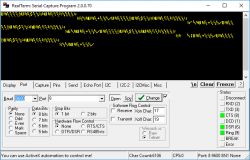
    Teardown of the TH06 clock/thermometer/hygrometer and UART reverse engineering
    Communication appears to be binary. Although I was still considering that it is a text, but it has been scrambled with, for example, XOR before sending.
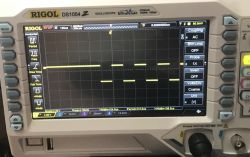
    In order to finally check what the baud is, I used an oscilloscope. All you need is a single trigger and the trigger set appropriately for the oscilloscope to catch the beginning of the signal and we get:
    Teardown of the TH06 clock/thermometer/hygrometer and UART reverse engineering
    One bit is 104us ... that's enough information for us. We can calculate baud now.
    (by the way, this Rigol has the possibility to unlock the RS232 debug mode in a certain versions, but I have not tested it yet, but it should be able to automatically read the byte values from UART signal)
    Baud is the number of bits per second.
    1s / 104us = approximately 9600 baud.
    We can also prepare a look up table beforehand to make time conversion to baud easier:
    Time Baud
    833us 1200
    416us 2400
    208us 4800
    104us 9600
    69us 14400
    52us 19200
    34us 28800
    26us 38400
    17us 57600
    8us 115200

    The results here are a bit rounded, if you get 108us it doesn't mean you have to count exactly and expect 9615 baud.
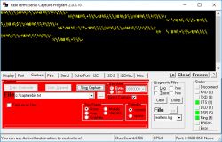
    Equipped with the information that the baud is really 9600, I checked the communication again, this time saving the received data to a file:
    Teardown of the TH06 clock/thermometer/hygrometer and UART reverse engineering
    In Realterm, you can save captured data to a file via the Capture tab.
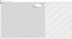
    I opened the file with my favorite hex editor, xvi32, which is available for free:
    Teardown of the TH06 clock/thermometer/hygrometer and UART reverse engineering
    XVI32 has a convenient 'data inspector' that allows you to view the data value interpreted as word, dword or float.
    You can see a repeating pattern in the data. Could it be packages?
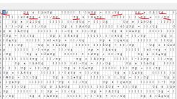
    Teardown of the TH06 clock/thermometer/hygrometer and UART reverse engineering
    The packages, however, are of different lengths. In order to facilitate further analysis, I wrote a C program to read in the data and verify whether there is a pattern repeating there.
    I started by loading the file:
    Code: c
    Log in, to see the code

    Then I made a loop iterating through it byte by byte and detecting the section header:
    Code: c
    Log in, to see the code

    Then I added skipping section data. As it turned out, after the section header (two bytes, U and the value 170) there are another two bytes which probably indicate the type of section. Depending on the type of section, different data is included in the package.
    Code: c
    Log in, to see the code

    The above code correctly goes through the entire file (except for one glitch a bit further in its content, but probably because of moving the cables from the UART).
    I then decided to write particular package data to separate files in some easy-to-understand form. Each package from a new line.
    Code: c
    Log in, to see the code

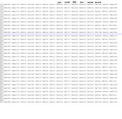
    Below is the result from the .txt file, with my comment (column names):
    Teardown of the TH06 clock/thermometer/hygrometer and UART reverse engineering
    It is very clear which byte is responsible for what. Information about the current year, month, day and time data are sent as separate bytes. The tenth hour is binary 10 (not '1' '0' in ASCII, only 0x0A byte). The other values are similar.
    Those repeating 0x01 may be an AM tag.
    One of the values here is probably also the pairing indicator and WiFi signal strength indicator.
    And the day of the week.
    I don't know what the last changing value is, maybe it's some checksum, CRC to validate the packet?
    The basis of the protocol is already known. I have not checked the communication the other way around, but it can be done in the same way. If the need arises, I will take care of it, and for now I will stop at this stage. You have the entire methodology of getting to know the protocol.
    And of course I know that you could look at XVI32 right away and not play with C processing, but it was so convenient for me and it allowed me to explore the whole thing much easier.

    WB3S programming
    It is worth mentioning that the process of compiling the SDK for WB3S has already been briefly described by me in the topic about XR809:
    https://www.elektroda.pl/rtvforum/topic3806769.html
    so it is probably possible to make your own firmware version for it, but more on that later.

    Summary
    Unfortunately, there are no big revelations here. The current date along with the temperature and humidity on TH06 looks quite aesthetic, but the product also has a lot of disadvantages:
    - the product requires a USB power supply (and it is often sold on the same website / offer as products very similar to it, but battery powered)
    - the product does not remember the date after losing power (so if there is no electricity in the house and there is no internet, the date will not appear on it)
    - the product cannot be changed to a 24h system (but the seller warns against it)
    - the product is based on WB3S, there is no ESP inside, so we will not upload our own firmware
    As for the pluses, I can praise the product for using a step down converter instead of LDO, always a bit more efficient. And at least the seller gave the USB cable in the set.
    I am enclosing catalog notes for the elements inside and related materials, including its manual in PDF format and the UART packages I have collected (but be warned that there is some glitch at the end of the file).
    Do you use this type of smart products, and if so, what specific model and in what environment? Zigbee, WiFi, Home Assistant or the manufacturer's application?

    Cool? Ranking DIY
    Do you have a problem with Arduino? Ask question. Visit our forum Arduino.
    About Author
    p.kaczmarek2
    Moderator Smart Home
    Offline 
    p.kaczmarek2 wrote 3935 posts with rating 4792, helped 179 times. Been with us since 2014 year.
  • #2
    rekinisko
    Level 22  
    A good bit of flipping a cat's tail, respect.
  • #3
    juan3211
    Level 5  
    Hi, nice post.

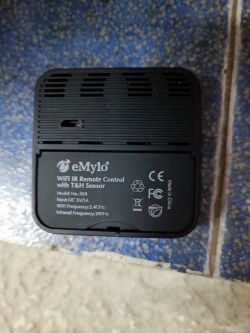
    I have a new version with the infrared stuff. But I did a big error. I desoldered the WB3S IC before trying to find this info.

    I have flash and solder an ESP12F to the board with tasmote firmware, I am trying to know how protocol works.

    I ahve found several things useful with tasmota firmware:

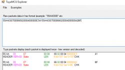
    I can get (once a minute) this info from the Tuya IC: {"SerialReceived":"55AA0307000865020004000000C54155AA030700086602000400000042BF"}
    These are two strings of information:
    55AA0307000865020004000000C642 and 55AA03070008660200040000003FBC
    55AA0307 - 0008 length - 65 dpId(101) - 02 dataType - 0004 length - 000000C6 value(=198) 42 (checksum) --> 19.8ªC temp
    55AA0307 - 0008 length - 66 dpId(102) - 02 dataType - 0004 length - 0000003F value(=63) BC (checksum) --> 63% humidity

    I dont mind about IR stuff at this moment, but I have a problem.
    I need to know which is the command that the WIFI MODULE sends to the TUYA IC to update DATETIME at boot.

    Probably, after booting up, the wifi module sends "something" to tuya IC (tx pin in wb3s) similar to hour time year, ....

    Could you please sniff it?

    I could give you all information about soldering and configuring tasmota firmware to get all data. It will be perfect to collaborate.

    I have only missing tha datetime stuff so the screen will look pretty!!!!

    Thanks a lot
  • #4
    p.kaczmarek2
    Moderator Smart Home
    The quoted command looks like indeed like a temperature and humidity. We have a tool for that:
    Teardown of the TH06 clock/thermometer/hygrometer and UART reverse engineering
    The command you are looking for is in our firmware:
    https://github.com/openshwprojects/OpenBK7231T_App/blob/main/src/driver/drv_tuyaMCU.c
    
    #define TUYA_CMD_SET_TIME      0x1C
    
    void TuyaMCU_Send_SetTime(struct tm *pTime) {
        byte payload_buffer[8];
    
    	if (pTime == 0) {
    		memset(payload_buffer, 0, sizeof(payload_buffer));
    	}
    	else {
    		byte tuya_day_of_week;
    		if (pTime->tm_wday == 1) {
    			tuya_day_of_week = 7;
    		}
    		else {
    			tuya_day_of_week = pTime->tm_wday - 1;
    		}
    		// valid flag
    		payload_buffer[0] = 0x01;
    		// datetime
    		payload_buffer[1] = pTime->tm_year % 100;
    		// tm uses: int tm_mon;   // months since January - [0, 11]
    		// Tuya uses:  Data[1] indicates the month, ranging from 1 to 12.
    		payload_buffer[2] = pTime->tm_mon + 1;
    		payload_buffer[3] = pTime->tm_mday;
    		payload_buffer[4] = pTime->tm_hour;
    		payload_buffer[5] = pTime->tm_min;
    		payload_buffer[6] = pTime->tm_sec;
    		payload_buffer[7] = tuya_day_of_week; //1 for Monday in TUYA Doc
    	}
    
        TuyaMCU_SendCommandWithData(TUYA_CMD_SET_TIME, payload_buffer, 8);
    }
    commandResult_t TuyaMCU_Send_SetTime_Example(const void *context, const char *cmd, const char *args, int cmdFlags) {
        struct tm testTime;
    
        testTime.tm_year = 2012;
        testTime.tm_mon = 7;
        testTime.tm_mday = 15;
        testTime.tm_wday = 4;
        testTime.tm_hour = 6;
        testTime.tm_min = 54;
        testTime.tm_sec = 32;
    
        TuyaMCU_Send_SetTime(&testTime);
        return CMD_RES_OK;
    }
    

    Does it answer your question? I can help more if you need.

    By the way, can you tell us how the IR format of your device looks like?
  • #5
    juan3211
    Level 5  
    Thanks a lot, after reading your source code, I have sent with tasmota this command, but.... not luck:

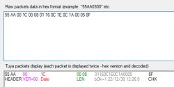
    serialsend5 55 AA 00 1C 00 08 01 16 0C 1E 0C 1A 00 05 8F
    (it is supposed to be 2022/12/30 12:28:00 Firday)

    Or may be I am doing something wrong?

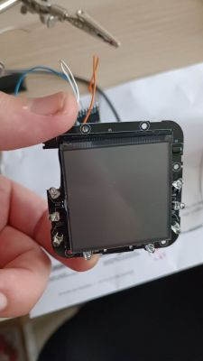
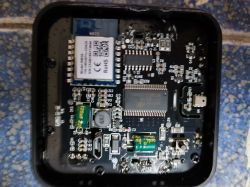
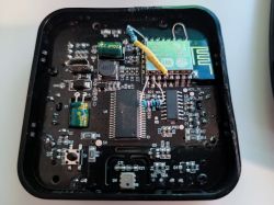
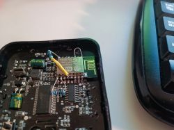
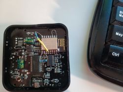
    (see attached images, one of them is old, before desoldering WB3S)
    Teardown of the TH06 clock/thermometer/hygrometer and UART reverse engineering
    Teardown of the TH06 clock/thermometer/hygrometer and UART reverse engineering
    Teardown of the TH06 clock/thermometer/hygrometer and UART reverse engineering
  • #6
    p.kaczmarek2
    Moderator Smart Home
    According to my packet analyzer the packet you have entered seems correct:
    Teardown of the TH06 clock/thermometer/hygrometer and UART reverse engineering
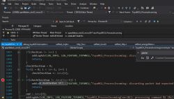
    although I didn't check checksum... let me see:
    Teardown of the TH06 clock/thermometer/hygrometer and UART reverse engineering
    hm, OpenBeken on Windows validates the checksum correctly.

    That's strange. I remember sending it by hand and it worked for my TH06.

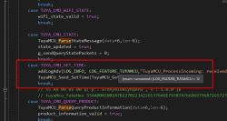
    OpenBeken, however, sends time only when requested by TuyaMCU:
    Teardown of the TH06 clock/thermometer/hygrometer and UART reverse engineering
    and not at random point of time.
  • #7
    juan3211
    Level 5  
    Ok, I will need to check how or when the device ask for the time, may be is it before tasmota boots up?

    any key?
  • #8
    p.kaczmarek2
    Moderator Smart Home
    I don't think that it may be before Tasmota boots up, because there is a whole process where the device first queries the WiFi state, etc. We have that in OpenBeken and it seems to work.

    I don't know how it is done in Tasmota. I must admit that I assumed Tasmota can also send the time automatically. You should check their source code.

    The second option is that the protocol changed and maybe they expect a different format. Packet capture from the new version of the TH06 would help.
  • #9
    juan3211
    Level 5  
    That is the problem, I have already desoldered the wb3s IC. It may be not work
    I will try to see your source code trying to see the order of dust command you are sending.
    May be tuya ic is waiting for an special order in commands (heartbeat, wifi ok, ... O whatever)

    Is there any good post explaining that order? I can try with Tasmota.

    Thanks
  • #10
    p.kaczmarek2
    Moderator Smart Home
    How did you desolder WB3S? Hot air?

    Also, by the way, is the IR connected in that version of device to WB3S or to TuyaMCU?

    Guide-to-I...ya-MCU.pdf Download (1.93 MB)
  • #11
    juan3211
    Level 5  
    Yes I have desoleder with a "type" of hot gun, but even that little piece of metal that it is over internal chips of wb3s has fallen off.
    So I don't know if wb3s will work or not, again.

    About infrared I will check it later, I want to have my LCD with good time 😜

    Any way I will check it for you.
    I think that I will by attached to tuya IC.

    In your source code where is exactly setup process of the tuya IC ? May be I can find the commands steps (heartbeat, product query, ....) to get it working.
  • #12
    p.kaczmarek2
    Moderator Smart Home
    The entire file, especially the TuyaMCU_RunFrame and TuyaMCU_ProcessIncoming handles the Tuya State Machine. Certain messages are sent in a reaction to a received messages, and some messages are sent periodically to the device, depending on WiFi and MQTT state.

    But isn't it already supported by Tasmota? Or are you saying that my firmware supports TH06 but Tasmota does not? I think Tasmota does support it, maybe we're missing something else?
  • #13
    juan3211
    Level 5  
    I am not using TUYA (54) in tasmota as configuration module. It gets into a boot loop and reset the configuration. I am just using serial comms with TuyaMCU.

    I have checked about IR, reciever is connected to PWM2 in wb3s (IO5 in esp12f), and emitters are in P14/IO16.
  • #14
    p.kaczmarek2
    Moderator Smart Home
    juan3211 wrote:
    I am not using TUYA (54) in tasmota as configuration module. It gets into a boot loop and reset the configuration. I am just using serial comms with TuyaMCU.

    I am sorry, but I am unable to provide support for Tasmota. I can only get it working for you in OpenBeken. It would be ironic if you had to solder back WB3S, but from what you said, pads are broken so it won't help much.

    juan3211 wrote:

    I have checked about IR, reciever is connected to PWM2 in wb3s (IO5 in esp12f), and emitters are in P14/IO16.

    This is indeed a useful information. We already have IR support in OpenBeken and it's fully scriptable. It would work in OBK well. And your device model seems to be... S09? Right?

    If you want, you can try providing here a current packets dump (with Tasmota flashed already) so we can see what's going on, but I am not sure if it would help much.

    You can also double check if Tasmota really sends out that packet as you execute that commands.
  • #15
    juan3211
    Level 5  
    Hi, S09 yes.
    I have get managed to get SETTIME working, command is correct, for example this one:
    2022/12/30 12:26:00 Friday
    serialsend5 55 AA 00 1C 00 08 01 16 0C 1E 0C 1A 00 05 8F

    But TuyaMCU doesnt send any answer.
    As I am using tasmota as generic module I will implement in nodered the time update as soon as tasmota "wakes up and send first payloads to mqtt".

    I have work now, but I will try also IR.

    Thanks.
  • #16
    juan3211
    Level 5  
    juan3211 wrote:
    I am not using TUYA (54) in tasmota as configuration module. It gets into a boot loop and reset the configuration. I am just using serial comms with TuyaMCU.

    I have checked about IR, reciever is connected to PWM2 in wb3s (IO5 in esp12f), and emitters are in P14/IO16.


    Sorry, mistake.

    These pins are now confirmed that works (I am using tasmota firmware, IRrecv gets data, and with IRsend GPIO14 I have managed to change my TV volume ;) )
    Reciever: GPIO5 IRrecv
    Emiter: GPIO14 IRsend

    (in photos you will see some space between ESP12F and PCB, It is intentionally)

    I hope this info is usefull

    Teardown of the TH06 clock/thermometer/hygrometer and UART reverse engineering
    Teardown of the TH06 clock/thermometer/hygrometer and UART reverse engineering
    Teardown of the TH06 clock/thermometer/hygrometer and UART reverse engineering
  • #17
    p.kaczmarek2
    Moderator Smart Home
    Thanks, I also see you had to solder extra resistor for ESP8266?

    Did you get TuyaMCU working with Tasmota?

    Btw, If you have other devices, please post teardowns here as well, we're building a database: https://openbekeniot.github.io/webapp/devicesList.html
  • #18
    juan3211
    Level 5  
    Yes, I solder two resistors, one for gpio15 to GND, and one for gio0 to 3.3v.

    I can't get tuya mode working, I get an automatic config reset because boot loop. I will try to ask in Tasmota why.

    Thanks.