F&Home configurator, creation of uniform automation of wired and radio devices
(Sponsored) .
.
I invite you to a detailed presentation/tutorial of the Configurator, a visual system for creating building automation of the Polish F&Home . I will show here step-by-step how it looks like to create action scenarios without any programming - everything will be assembled from intuitive and configurable nodes, commonly called blocks. I will present here the available types of them and examples of the ways in which they can be combined.
The topic does not require any knowledge of programming, let alone we will be writing code here. Automation in F&Home can easily be created by the user himself, all thanks to the visual layer based on Node Red, which sets the Configurator apart from other systems.
But first I would like to remind you of the previous section, in which I gave a presentation and overview of the F&Home hardware. The F&F range includes scalable wired and wireless solutions, all of which the Configurator can precisely control. We are only limited by our imagination.
F&Home - Polish building automation system, first step commissioning .
Now we can move on to the actual presentation. In this case I have also created a text description and a video. If you are interested in the video, I have placed the link at the end of the topic.
First steps .
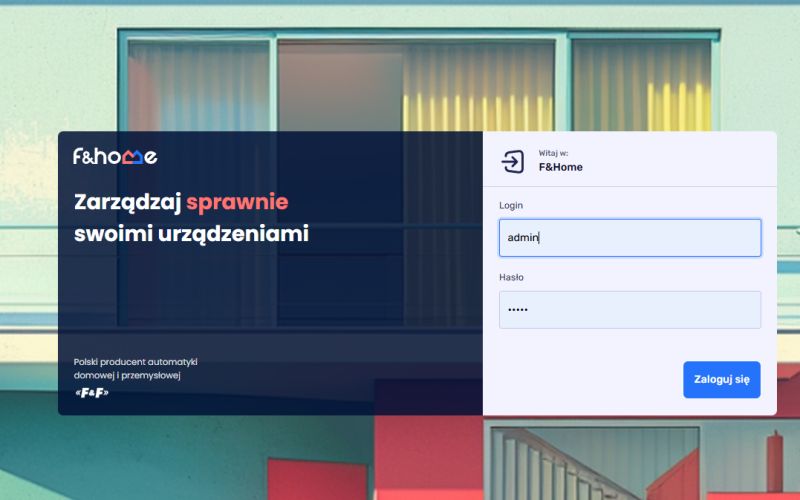
We start the adventure by logging into the central unit. You will find the default login and password in the manual.
 .
.
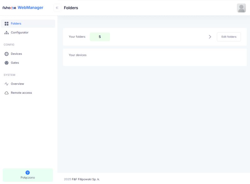
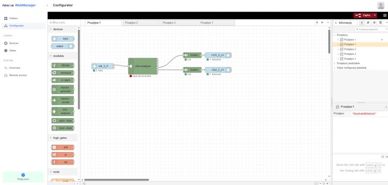
After logging in, we are greeted by the tabs: Folders (folders, for organising devices), Configurator (here we create logic in the Node-Red visual layer), Devices (list of devices), Gates (gateways), Overview (system overview, CPU, memory), Remote access (remote access).
 .
.
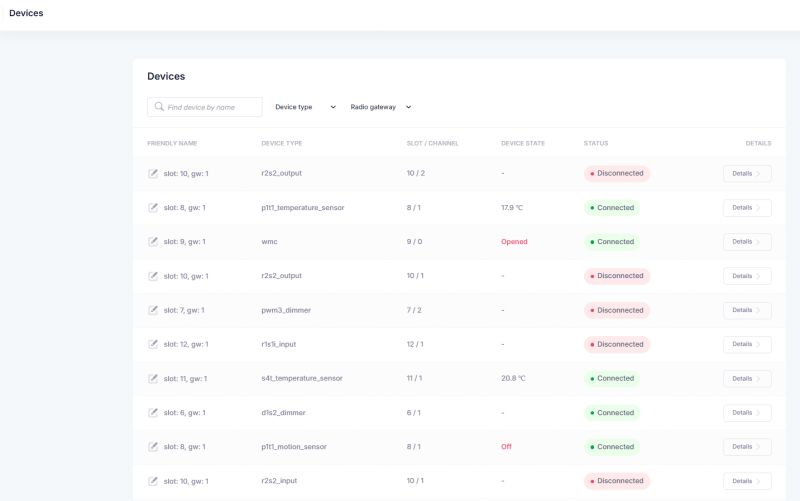
The Gates and Devices tabs are probably already familiar from the previous section, as we added devices there:
 .
.
We will now focus on the Configurator:
 .
.
On the left-hand side we have the available nodes, such as inputs/outputs from devices, modules that perform given operations, logic gates, tools or there access blocks to the modbus interface and to the mobile application.
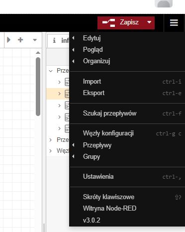
On the right-hand side, we have information about the flows, a "Save" button and a menu allowing, among other things, the export and import of flows from a file.
 .
.
In the middle, meanwhile, we have the flows in question - there can be many of them. Control is very simple:
- a block is added to a flow by dragging it with the mouse
- blocks are also connected by clicking and dragging between their inputs/outputs
- double left click to activate block settings
- single left click selects the object
- delete deletes the selection
- right click opens context menu
- of course, shortcuts such as CTRL+C (copy) or there CTRL+Z (undo) also work
First flow .
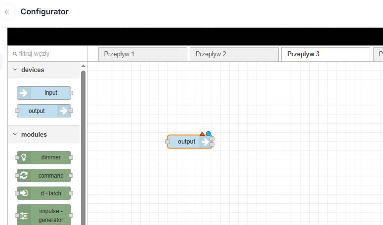
Let us therefore drag the output node to the flow:
 .
.
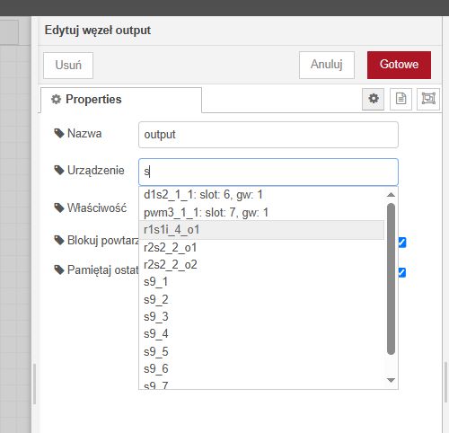
Let's double-click it - in its options, let's at least select a button, maybe the one from rH-S4T:
 .
.
Let's save the flow:
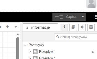 .
.
From now on, the status on the selected input is visible at the node, the whole is refreshed in real time:
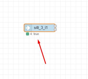 .
.
So let's add a second node - the output node - and select some, say, relay in it. The whole thing also needs to be connected by a line:
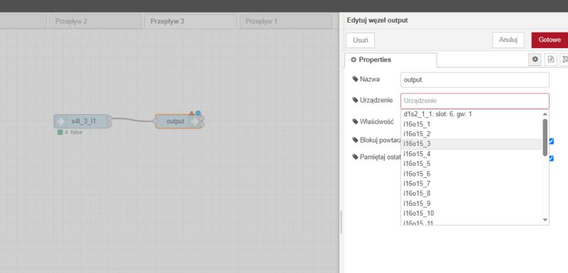 .
.
From now on, the state from the output is rewritten to the input. Simple. I put the whole thing together twice:
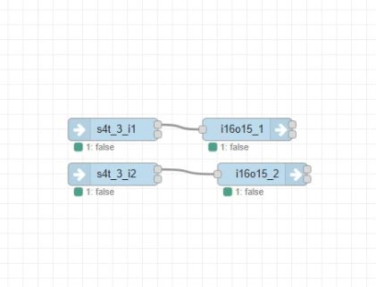 .
.
Video presentation:
Logical gates .
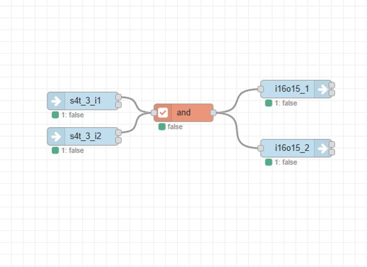
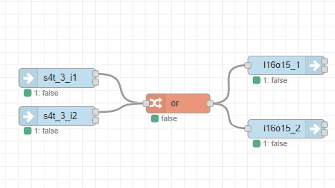
Now that we have two inputs and two outputs, it is tempting to test logic gates. All we need to do is to drag such a gate into the flow and then connect it accordingly. An AND gate (logical product) only returns a high state when the inputs have high states alone, while an OR gate (logical sum) returns a high state when at least one input has a high state.
AND gate:
OR gateway:
 .
.
Click state switching, i.e. a D-type flip-flop .
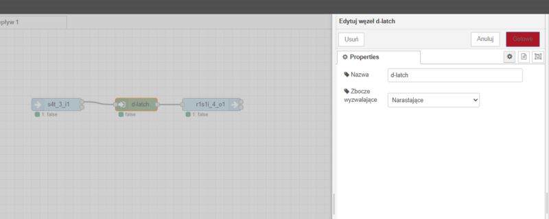
The examples shown so far essentially directly transcribe state from input to output. This provides a good demonstration of the functionality, but is not practical. Typically, rather, monostable, momentary buttons are used in automation, which you press once and then they themselves return to their previous state. Such button presses should toggle the state of the relay, so you might as well flip the relay remotely.
 .
.
We add a node and set its trigger edge to rising.
It is worth noting here that such a flip-flop has a memory and holds its state until the next change.
Physical pushbutton and app control .
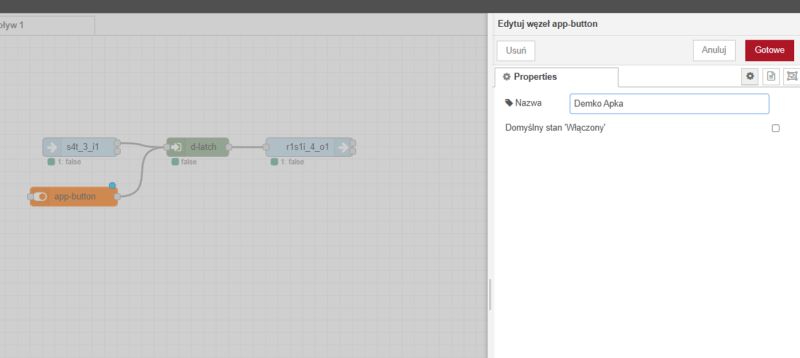
I also announced the control from the app earlier. Now it is time to realise it. For the example with the D-type flipper, I have additionally connected an app-button node, i.e. a button displayed on the desktop application.
 .
.
From now on, these two nodes can jointly control our flipper. The light works with the app and with the switch. Just like in the video:
Button events .
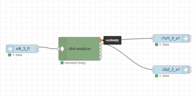
We have already handled the flipping of device status in a simple way with a short click, but there is still room for improvement. After all, it is possible to separate separate events related to the button, such as short or long press (more precisely: release after a short or long press) or there a separate event of pressing, releasing, etc. A separate node is used for this:
 .
.
Its individual outputs correspond to separate events. It also allows you to set a cut-off time distinguishing between long and short click.
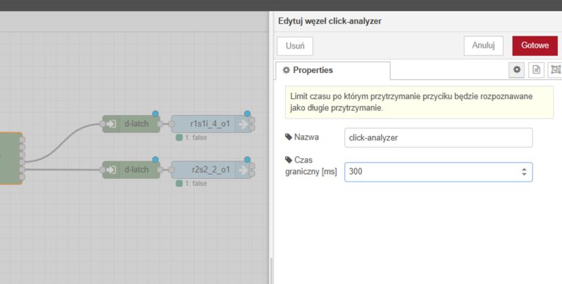 .
.
The click analyser node has outputs in sequence:
- pressed
- long pressed
- released
- released after short press
- released after long press
- value from the input
Accordingly, we connect further nodes to the outputs we are interested in. And don't forget the flip-flops. In this way, one button can control two receivers - example result:
Time and sunrise/sunset .
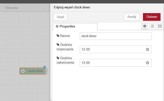
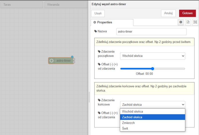
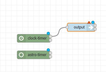
The next two useful nodes are timers. We have two types of them:
- clock timer, which issues logical values based on the current time
- an astro timer, which is based on the current time of sunrise and sunset (with configurable offset)
 .
.
This allows, among other things, the lights to be automatically switched on when darkness falls or sprinklers to be activated at a selected time. Both timers have two outputs each, alternating between a low or high state, depending on whether the condition is met.
 .
.
Inject node .
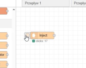
It is also useful to know the Inject node - it reacts to clicks in the configurator itself, this allows you to conveniently test the system. Under the node, the number of clicks is visible.
 .
.
In this way, flows can be triggered in the same way as normal buttons or a button from the Fox app (app-button).
Counter example (pulse-counter) .
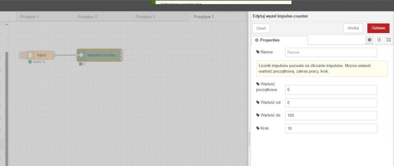
We will now learn about the counter node. The demonstration will be based on the mentioned inject. Let's configure the counter so that the initial value is zero, the range is from 0 to 100 and the step is set to 10:
 .
.
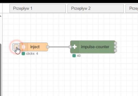
Increasing the counter works, however, there is a problem - the value stops at 100 and does not loop.
 .
.
However, this can be easily fixed. This node has three outputs - the current value, a logic state telling us if the maximum value has been reached and a logic state telling us if the minimum has been reached.
This allows us to use the logical product block and the reset command block (command block with the reset command selected) to reset the counter. When the value 100 is reached, another click sets the counter to zero.
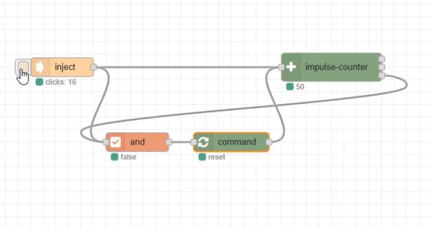 .
.
The way this works is that the signal from the inject and from the pulse counter (the state of reaching the maximum) enters the AND node. So the AND will only give us a high state when both conditions are met, and then the command is triggered.
Impulse-counter for dimmer control .
We now have a numerical value from 0 to 100 that can be controlled by the user. This can be easily exposed to a dimmer for example:
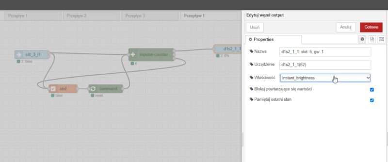 .
.
In this way, we have created our own dimmer control logic, which can always be adapted to your own preferences if necessary.
Value from the dimmer control app .
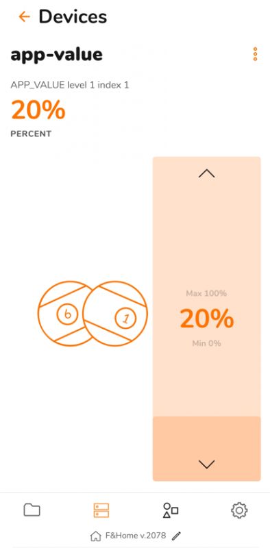
Numerical values can also be set from within the Fox application. This is done using the App-Value block, which can represent different quantities - temperature, percentages, number, etc. Limits and step size can also be selected.
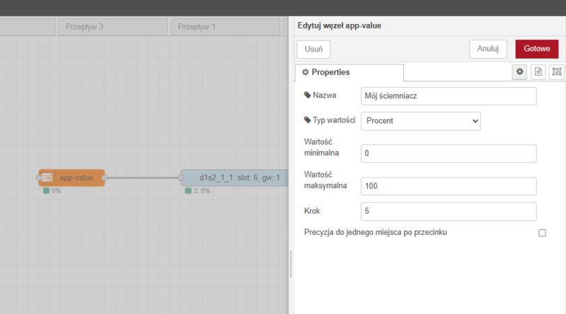 .
.
In this case, we have selected a percentage, a range of 0 to 100, a step of 5, and connected the output of this node to the input of the dimmer.
From now on, we essentially have ready control of the brightness of the bulb from within the app.
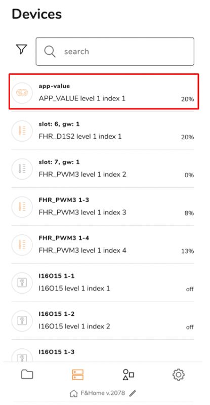
 .
.
Video presentation:
This solution gives us a great deal of control and offers a high degree of configurability. We can, for example, reduce the maximum brightness level of an LED bulb or strip, extending its life and reducing energy consumption.
Dimmer node .
I didn't even use this in the previous example, but it's worth mentioning anyway that a ready-made dimmer offering configurable transition times is also available among the nodes.
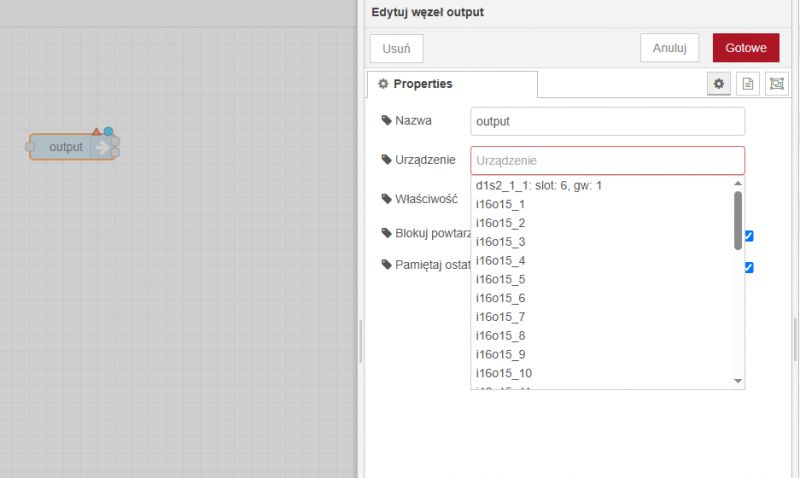
We add a general-purpose Output node. In it we select our dimmer, the node type will be refined.
 .
.
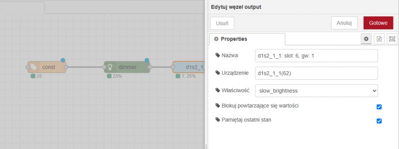
You can now fine-tune the operation of the dimmer in it, e.g. set a slow brightness change.
 .
.
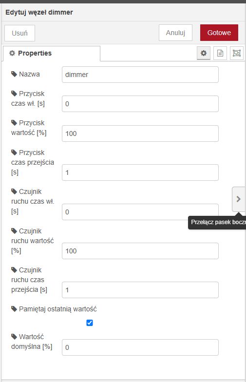
We also add the Dimmer node, giving us additional functionality regarding light:
 .
.
Finally, for an example, a const node can be given as input - a constant value, say, 25% - 25% brightness.
 .
.
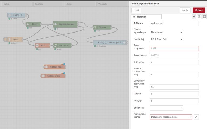
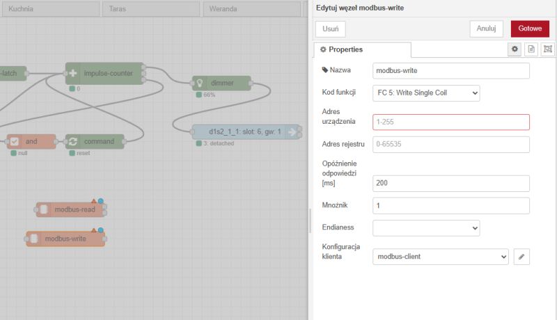
Modbus interface .
Finally, it is worth mentioning the nodes that allow communication via Modbus. These allow connection to external systems.
 .
.
 .
.
Import and export to JSON .
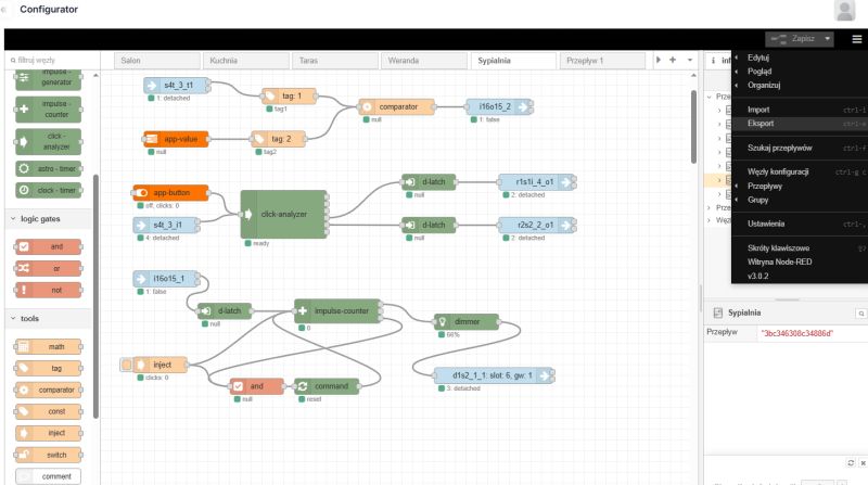
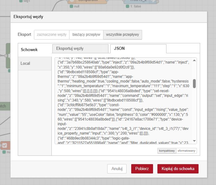
The visual layer also allows the logic to be easily written and read into a file in JSON format. The "Import" and "Export" options in the menu on the right are used for this:
 .
.
 .
.
A given file can also be imported several times (as separate flows), which makes it easier to repeat the same logic when we have several pieces of a given set of devices.
Footage
Equipment used for presentation
mH-DEVELOPER - F&Home system central unit, DIN rail mounted, controls lighting, heating and sockets, operates wired and wireless modules when connected to a gateway.
mH-SP - Interference filter protects the system from mains interference and surges..
mH-SU50 - 24V power supply, provides voltage for the mH-Developer server, connected between the mH-SP filter and the CPU.
mH-IO12E6 - Expansion module for mH-Developer, controls lighting and motorised receivers (blinds, shutters).
mH-IO12E6B - Newer version of the mH-IO12E6 module, extends the functionality of the server.
mH-R8x8 - Executive relay module, connected to the mH-IO12E6, controls lighting or other consumers.
mH-V8 - Eight-channel executive module for controlling solenoid valves in heating systems, interfaces with mH-S8.
mH-S8 - Eight-channel temperature controller, works with DS18B20 sensors, controls solenoid valves via mH-V8.
mH-RE4 - Roller shutter relay module with protection against simultaneous activation.
rH-R1S1 LR - Radio box module with relay and contact input, controls electrical circuits such as lighting.
rH-P1T1 LR - Battery operated motion sensor with temperature probe, triggers automation in the system, powered by two AAA batteries.
rH-S4T - Battery operated four channel transmitter with temperature probe, supports quadruple button.
rH-PWM3 LR - Three channel PWM driver for LED lighting and other low voltage devices.
rH-WMC - Battery-operated door/window sensor based on reed switch, triggers scenarios, e.g. light on.
rH-R2S2 DIN LR - Two-channel relay with transmitter, DIN rail mounted, controls two receivers and buttons.
rH-D1S2-LR - Radio dimmer with standalone mode, controls lighting brightness.
Summary .
The new Configurator at F&Home allows for uniform programming of wired and wireless devices. Each device can be freely linked to other devices and can also be controlled from the mobile app, triggered on a time/sun status basis and even linked to external systems via modbus.
Creating automations in the Configurator is simple and intuitive; in principle, you do not need to know any programming skills to be able to click out the various dependencies in it. Everything is assembled from ready-made, but at the same time configurable blocks.
The Configurator offers many useful features - for example, you can keep track of the values of the inputs and outputs in real time, as well as change these values via the inject block.
In summary , the Configurator is a convenient and accessible solution, which allows automation to be freely created by both fitters and customers..
[Advertising collaboration with F&F Filipowski sp.k.].


Comments
Is this a normal Node RED or some kind of manufacturer's cut-down version? Is it possible to install any external modules? [Read more]