logo elektroda
logo elektroda
X

Mystery electronic component from a digital device

TechEkspert 3450 28
ADVERTISEMENT
Treść została przetłumaczona polish » english Zobacz oryginalną wersję tematu
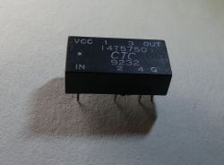
  • Black CTC 14T5750 relay with labeled pins on top surface
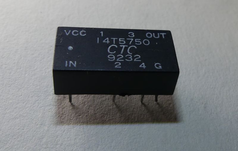
    When I visited an electronics colleague recently, he surprised me by putting a small object on the table and asked what the electronic component could be. The component was working on a board in digital circuits. On the casing you will see the markings VCC, GND and OUT. You might suspect that this is some sort of quartz generator, such as DS32KHz or higher frequency generators such as TCXO . Also visible on the chassis is the designation of an input, perhaps controlling the operation of the circuit, and several outputs marked with consecutive numbers.

    Do you know what this electronic component is used for?

    I was wrongly betting that it was a quartz generator. On old computer motherboards I often saw several generators with different frequencies, usually enclosed in a metal case. Apparently PLL circuits were not used then and it was easier to use several generators with different frequencies.

    Black integrated circuit labeled “14T5750 CTC 9232” with four pins below


    After typing the symbol 14T5750 into google, it was possible to find descriptions of 286 motherboards where this component was used:
    https://theretroweb.com/motherboards/s/auva-computer-baby-286-bam-12-g1
    https://theretroweb.com/motherboards/s/morse-kp286hf

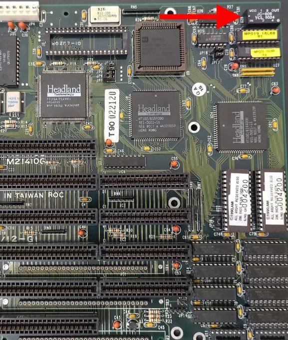
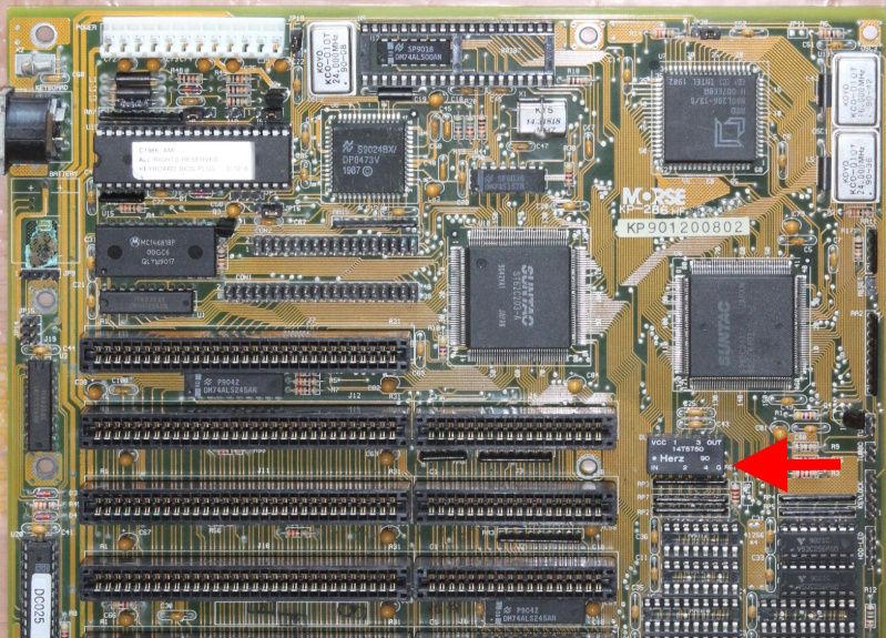
    Below are screenshots from the found pages with the undetermined purpose element highlighted. Miniature DC/DC converters are now available in similar enclosures, but this component is not an inverter.

    Motherboard from the 1980s–90s with Headland chips and ISA slots


    Close-up of 1980s computer motherboard with ISA slots and marked components


    Managed to find a pdf describing the parameters of this component:
    http://www.datasheet.hk/view_download.php?id=1695449&file=0349%5C14t5750_2726584.pdf

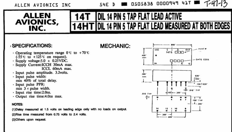
    It turns out that the manufacturer supplied more models of this component: 14T5750 14HT5750 14HT5125 14HT5251 14HT5500 14T5451 14T5500

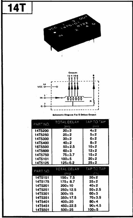
    The riddle is explained by the contents of the pdf:

    Technical diagram and specifications for Allen Avionics 14-pin DIL device


    Diagram and delay specification tables of 14T delay line component


    This is a delay line! The circuit is powered by 5V, has an output and several 'taps' with different delays to the input signal. What could such a delay line have been used for on the motherboard of a computer with a 286 processor? I suspect that it was a way of distributing timing signals, with a specific offset/delay of the signal edges. Such an offset may have had applications, for example, in controlling RAM operation. If board schematics with such a line were available, perhaps something could be confirmed.

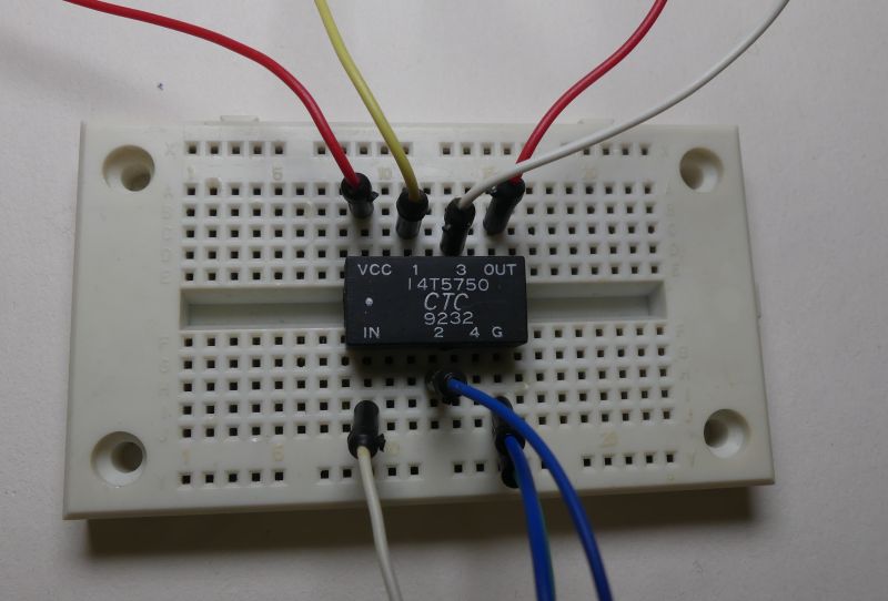
    Let's see if the line still works. We supply the circuit with 5V -> current consumption about 17mA. We apply a 100KHz signal to the input and the current consumption increases to about 32mA. It appears that the embedded circuitry in the line is working.

    14T5750 CTC IC connected to breadboard with jumper wires


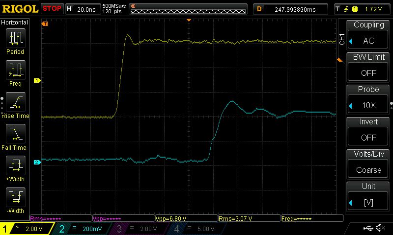
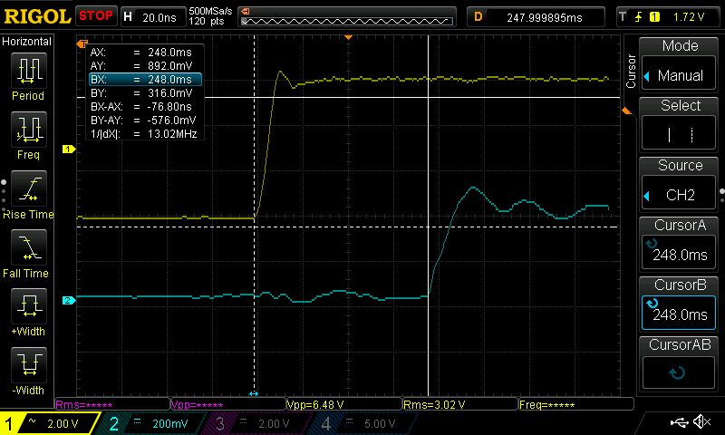
    This is what the IN input signal (yellow trace) and the OUT output signal (blue trace) look like. The action of the delay line is visible.

    Oscilloscope screen showing two voltage waveforms in different colors


    The offset is approximately 76ns according to the parameters in the description.

    Oscilloscope screenshot with two waveforms: yellow and blue, showing amplitude and time measurements


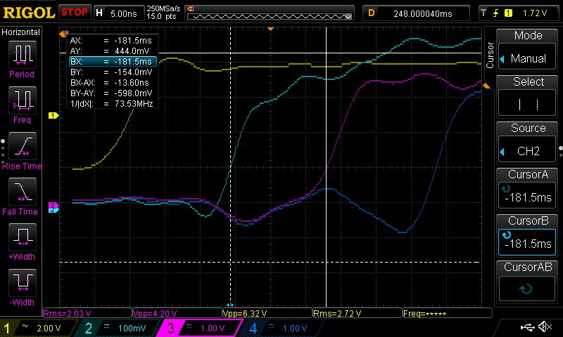
    This is what the signals look like on the next "taps" of the line relative to the IN signal:
    Rigol oscilloscope screen with four electrical signal waveforms displayed


    I was not aware of such a solution for distributing timing signals and delaying digital signals. Although I have seen solutions where gates were used to influence the signal propagation, but then the delay times were shorter.

    Have you encountered the use of delay lines in digital devices?

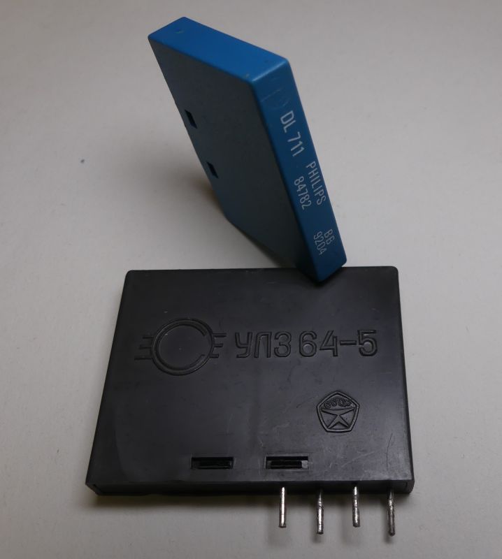
    By the way, I am posting pictures of another familiar delay line that was used in analogue TV sets . Specifically, such delay lines were found in PAL decoders. The line delay was 64µs .

    Black Soviet chip УЛЗ64-5 and blue module labeled DL-711 PHILIPS


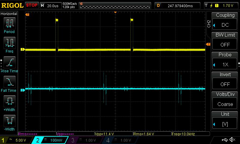
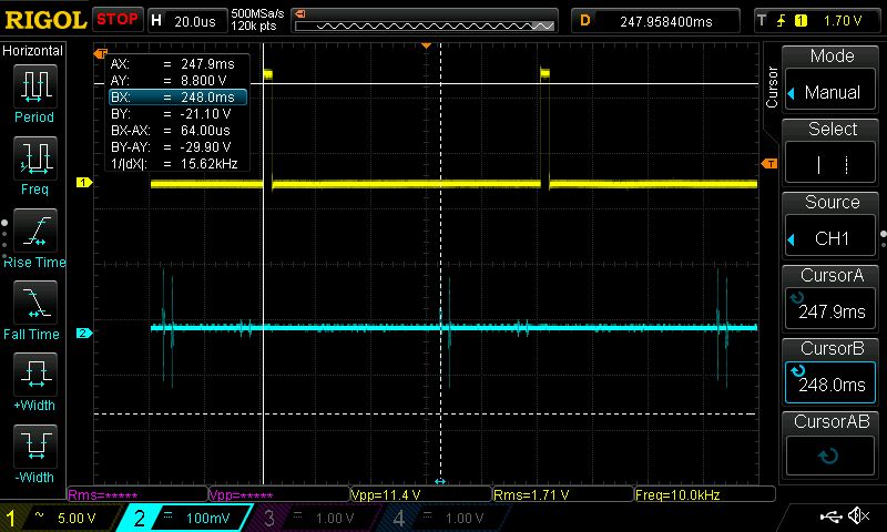
    We feed the pulses into the input (yellow trace) and at the output (blue trace) you can observe the pulses appearing with a delay.

    Oscilloscope screenshot with two channels: one pulsed signal and one with noise


    The delay is 64µs:

    Rigol oscilloscope screenshot with yellow digital and blue analog waveforms


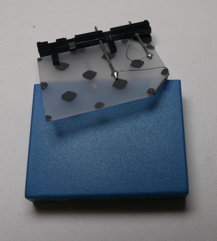
    Let's take a look inside the 64µs delay line.

    Sensor prototype with metal wires on transparent board with black dots


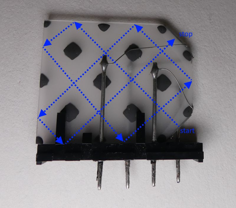
    The signal travels a rather complex path in the quartz plate, bouncing at its extremities. Thanks to the multiple reflections, the dimensions of the device can be smaller.

    Interior of an analog delay line with signal path marked


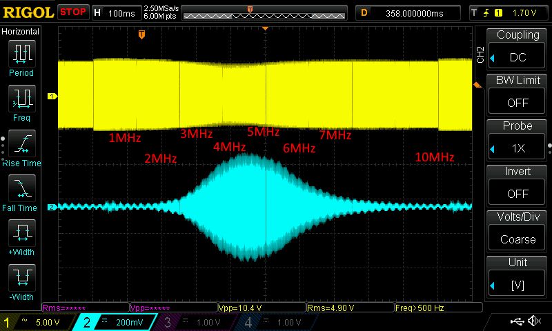
    Estimating the frequency response with an oscilloscope and tunable generator , the result is quite predictable, the amplitude peaks between 4-5MHz. You can also see that the line loads the generator output, the amplitude of the input signal varies over a small range.

    Oscilloscope screen with AM signal and modulating waveform from 1–10 MHz


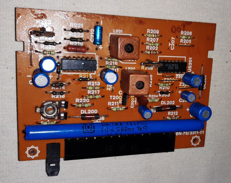
    SECAM decoders also included a delay line which was a long thin wire wound around a tube the size of a ballpoint pen. The delay of such a line was less than that of a 64µs line. Below is an example of a module with a 560ns line.

    Circuit board with blue delay line UNITRA TELPOD LD-4 560ns 1kΩ


    The delay lines used in televisions are still well recognisable, but with the passage of time, like the 14T5750, they can be a puzzling object for their finder.

    Delay lines were used in oscilloscopes with a delayed time base. In the early days of computer science and calculating machines, operational memories were built on the basis of delay lines. Bits circulated in a delay line and were re-transmitted to the line after being received. This is how mercury memory worked.

    Cool? Ranking DIY
    About Author
    TechEkspert
    Editor
    Offline 
    TechEkspert wrote 6606 posts with rating 5192, helped 16 times. Been with us since 2014 year.
  • ADVERTISEMENT
  • #3 21709668
    TechEkspert
    Editor
    An interesting stage where the timing of the RAS/CAS signals was determined by the physical parameters of the soldered-in delay lines. A significant technological leap occurred when configuration was done from the BIOS manually or even from the SPD.
  • #4 21709745
    E8600
    Level 41  
    Where can such an electronic component be used in DIY projects?
  • #5 21709786
    gregor124
    Level 27  
    >>21709745
    Maybe not like this, but e.g. with more delay to produce an echo effect?

    Delay lines were e.g. mercury memories in the early days of computers.
    Helpful post? Buy me a coffee.
  • #6 21710035
    TechEkspert
    Editor
    It is rather hard to find a sensible use for these components at the moment, although perhaps I have a poor imagination :)
    If this delay line can be opened I will also post pictures showing the internal construction.
  • #7 21710109
    omron
    Level 17  
    ad vocem:
    ''Specifically, such delay lines were found in PAL decoders'' - this ''64us chrominance delay line'' - was in SECAM decoders too !!!
    ''In SECAM decoders there was also a delay line which was a long thin wire wound on a tube the size of a pen...'' - this ''560 ns luminance delay line''

    :)
  • #8 21710130
    TechEkspert
    Editor
    To date, I cannot write from memory what the 64µs delay line in SECAM and PAL decoders was used for, let alone the 560ns line in a PAL decoder.

    Maybe one day someone on elektroda.pl will post an article about PAL and SECAM decoders then I will 100% read it from cover to cover :)

    I remember the transition from SECAM to PAL, on some televisions you could plug in a circuit that plugged into many places on the TV and when you cut selected tracks allowed colour reception in PAL. More convenient were the ready-made modules available on Wolumen for certain TV models, where you removed the old module and inserted the new decoder.

    Another less complex topic was the transition of FM radio broadcasting from OIRT to CCIR, this started a massive tuning of receivers, although there were also converter modules incorporated into the antenna circuit.
  • ADVERTISEMENT
  • #9 21710168
    coberr
    Level 20  
    >>21710130
    TechEkspert wrote:
    To date, I cannot write from memory what the 64µs delay line in SECAM and PAL decoders was used for, much less the 560ns line in a PAL decoder.


    Not surprisingly.... hardly anyone today knows how decoders work - in fact, only the "old guard" ...
    while the youngsters don't even have a "drive"... :)
    The line served precisely to delay the luminance signal by one whole processed line - at which time the chrominance signal was processed. (i.e. 64us).As a result, both signals reached the final tracks - at the same time.
  • #11 21710419
    ZbeeGin
    Level 39  
    coberr wrote:
    The line served exactly to delay the luminance signal by one whole processed line - at which time the chrominance signal was processed. (i.e. 64us).As a result, both signals reached the final tracks - at the same time.

    Unfortunately you have simplified this considerably. The colour decoders of older TV sets had two delay lines:
    - 64µs in the chrominance path, processing colour information,
    - 0.7µs in the luminance path, responsible for brightness information.

    And now, depending on whether the decoder works in PAL or SECAM, the first 64µs line has a different function.
    In the PAL system, it is used to store colour information from the previous picture line in order to correct phase shifts that can lead to colour distortion. The PAL system carries the differential colour signals in "vector" form - both at once, so-called quadrature modulation.
    In the SECAM system, it is used to store information about one differential signal for the process of correct decoding. The SECAM system transmits the colour differential signals sequentially, every line - hence it has a lower vertical resolution of the picture in relation to the colours.
    In both cases, the ~0.7µs luminance delay line is used to equalise the propagation times of the colour and brightness signals so that there are no colour fringes in the image.
  • #13 21711019
    tytka
    Level 22  
    gregor124 wrote:
    Maybe not such, but e.g. with more delay to produce echo effect?


    In echo and reverberation circuits, however, it is definitely higher delays that are needed compared to what this line offers.

    In the old echo and reverberation systems, spring-loaded systems were very often used.
    For those who don't know such a thing, I recommend at least this material: Link
  • #14 21711032
    TechEkspert
    Editor
    @gregor124 I didn't know that, is this some kind of scrambling?
    In a typical block or stream encryption, I don't see the need for such a line.

    @tytka I associate echo with the period after spring reverb and before fully digital solution. It was a cascade of memory cells where a sample of voltage was stored. A timing signal moved these memorised signals in successive cells in the chip. This was similar to the solution in the ISD series sound chips, where a single cell, stored an 'analogue' voltage sample.
  • ADVERTISEMENT
  • #15 21711061
    gregor124
    Level 27  
    Of more interesting applications, for example, they were used in some very high-speed analogue oscilloscopes, so that you could see, for example, the signal with a delay before the trigger signal appeared.
    Helpful post? Buy me a coffee.
  • #16 21711062
    acctr
    Level 39  
    In general, the higher the frequency, whether of a mechanical or electromagnetic wave, the shorter the delays. It may be interesting to note how strings were used by Galileo Galilei to discover the laws of nature, such as gravity.
    Helpful post? Buy me a coffee.
  • #17 21711171
    tytka
    Level 22  
    TechEkspert wrote:
    I associate echo with the period after spring reverb and before fully digital solutions.

    I also associate such solutions,

    And the spring, I had the opportunity to play with quite recently. I had to repair a Pioneer QX-9900, which has reverberation effects realised with such a device. By the way, I demonstrated this solution to a colleague, who had never encountered it before :)
  • #18 21711514
    gregor124
    Level 27  
    >>21711032
    This worked on the principle that the signal was split into a number of short time intervals and each section was passed through a different (code-set) delay.
    The result was that the signal was slightly delayed and each section of the time interval appeared in a different order, making the recording completely unintelligible.
    It was only in the receiver that the signal was re-processed by appropriately timed delay lines, which put each such interval in the correct order and it was now correctly audible.
    Such a device caused a slight delay, but was very effective.
    Helpful post? Buy me a coffee.
  • #19 21711880
    minus3db
    Level 12  
    Speaking of oscilloscopes - a beautiful and massive (gigantic!) delay line has a Polish oscilloscope made by ZRK OS-150. It consists of several coils of coaxial cable in an outer braid. It looks interesting, and extends over the entire height of the oscilloscope (about 45cm).
  • #20 21712234
    cirrostrato
    Level 38  
    TechEkspert wrote:
    I still can't write from memory what the 64µs delay line was used for in SECAM decoders

    The old memory still works, you need from the received signal to reconstruct three colour signals plus luminance (the one sent in each successive line), in successive lines sent one of the two colours hence the need for delay to have two at the same time, the third was formed from the combination of the line signal and these two colour signals, together a set to drive the cathode ray tube. That's it roughly, a more detailed description of the subject is unnecessary, it's already prehistory.
  • #21 21712835
    thereminator
    Conditionally unlocked
    tytka wrote:
    tytka wrote:
    TechEkspert wrote:
    I associate echoes with the period after spring reverberation and before fully digital solutions.

    I also associate such solutions,

    And the spring, I had the opportunity to play with quite recently. I had to repair a Pioneer QX-9900, which has reverb effects realised with such a device. By the way, I demonstrated this solution to a colleague, who had never encountered it before :)


    Clearly you have not dealt with 'guitar' equipment. In modern production tube guitar amplifiers, especially in combo cabinets, it is still quite common to use spring reverb.

    And going back to the subject of delay lines, an interesting solution was used in calculators in the 1970s: https://www.olek.waw.pl/kalkulator-iskra-111/
  • ADVERTISEMENT
  • #22 21715739
    coderemover
    Level 5  
    They are also used to realise broadband transformers in radio and microwave technology. At the same time, these are usually much shorter delays. If you wind a transformer classically, each winding separately, you are limited in bandwidth by the parameters of the core and the magnetising inductance. If you want a transformer to work from kilohertz to hundreds of MHz or even GHz then you construct it from transmission lines. See, for example, the 1:4 Guanelli transformer, which has two transmission lines with the same delay, where one is wound on the core and performs the actual transformation and the other is just to delay the signal to compensate for the delay in this first line.

    https://www.allaboutcircuits.com/technical-ar...g-the-guanella-transmission-line-transformer/
  • #23 21716313
    TechEkspert
    Editor
    This is a completely new topic for me, I was not familiar with the use of delay lines together with transformers.
    I wonder what kind of delay would be introduced by the primary winding of a mains transformer if it were treated as a delay line.
  • #24 21716374
    acctr
    Level 39  
    TechEkspert wrote:
    I wonder what delay would be introduced by the primary winding of a mains transformer

    The delay of such a winding is due to its inductance and is in phase. The delays described above arise from the displacement of the wave, so it is something else.
    Helpful post? Buy me a coffee.
  • #26 21717925
    TechEkspert
    Editor
    I found a symbol for an analogue line circuit with 1024 elements that used to be used in audio. It is the MN3207 https://elecena.pl/datasheet/251854/mn3207
    The memory elements are mosfet transistors and capacitors. I associate this circuit with "echo" pickups for CBs. Nowadays such an echo/reverb can be done by a microcontroller with more RAM.
  • #28 21718079
    thereminator
    Conditionally unlocked
    TechEkspert wrote:
    I found a symbol for an analogue line circuit with 1024 elements that used to be used in audio. It is the MN3207 https://elecena.pl/datasheet/251854/mn3207
    The memory elements are mosfet transistors and capacitors. I associate this circuit with "echo" pickups for CBs. Nowadays, such an echo/reverb can be done by a microcontroller with more RAM.


    The MN3207 is a BBD ('bucket brigade device') type chip. It was used in flangers (e.g. BOSS FL-2 or Exar FL-1) due to its short delay time, It was clocked by the MN3102 integrated generator. A similar chip with 512 cells was designated MN3204 (in the BOSS HF-2). In contrast, the MN3007 chip was used in choruses (BOSS CH-1 and later versions of the EHX Small Clone).

    acctr wrote:
    Interesting solutions can be found in analogue and digital synthesisers, where delay is implemented as digital memory, some of the simpler ones Monotron Delay and PT2399 , SAM2635 .


    The original PT2399 and others in this family were designed as delay circuits for early home cinema and karaoke. Nowadays they are mainly used in toys and boutique and DIY delay effects for guitar (e.g. Mad Professor Deep Blue Delay and its clones). On a Chinese portal, you can buy a ready-mounted PCB for a few zlotys, from which, with minor modifications and the addition of a few components (not counting the housing), you can assemble a delay effect for a guitar or keyboard instrument.
  • #29 21723181
    coderemover
    Level 5  
    TechEkspert wrote:
    I wonder what kind of delay would be introduced by the primary winding of the mains transformer if it were treated as a delay line.


    Not really possible, because the mains transformer winding is wound separately primary and separately secondary. This would be an extremely poor delay line. In those broadband transformers I wrote about above, the windings are wound with either coaxial or twisted pair wires (2 or even 3 wires first twisted and only wound on the core in this way).
ADVERTISEMENT