Restored a prototype Rochar A.1335 digital voltmeter from the early 1960s, one of Europe's first digital voltmeters.
Rebuilt the power supply on a new board, replaced dried electrolytic capacitors, repaired wiring, and swapped the failed 2N555 stabilizer with a stronger 2N1558.
Fixed the counting and range circuits by replacing an open diode in the ÷5 divider, a shorted diode in the decade/range logic, and a broken reed relay contact.
Limited the NIXIE supply to 180V, fitted LC513 tubes, and calibrated the reference section around a 6.2V diode and precision 1200Ω and 4kΩ resistors.
The voltmeter now measures correctly on all ranges; DC is stable and AC is reasonable up to 10 kHz, though accuracy drops above that.
Generated by the language model.
Renovation of vintage Rochar A.1335 digital voltmeter
Good afternoon,
some time ago I received a vintage voltmeter handmade in the early 1960s from a friend in France. I have restored this instrument, I invite you to report on the repair of this vintage device. Perhaps a few words about the restoration of this beautiful instrument will encourage someone to restore technical relics? Or maybe someone will be interested in the history of electronics development?
The first digital voltmeter was developed by Andrew Kay in the USA in 1952, using fast relays. It had an interesting display: transparent glass panes with engraved digits illuminated at the edge by an incandescent bulb. There was one digit on each pane, 11 panes and bulbs for each digit, including the comma. The first copy of this device was sold to the US Army in 1953 and series production began in 1954.
HP launched the first transistorised digital voltmeter with NIXIE tubes in 1959. The history of digital voltage measurement began in the USA, and everyone knows the companies FLUKE, HP, Tektronix. However, not much is said about European designs, here is one of them:
The first, conceptual design of the A.1335 voltmeter was presented in a brochure in October 1963 (England's Solartron presented a similar model, the LM1420, in 1964).
The A.1335 series-produced voltmeter appeared in the official Rochar catalogue in 1964. It was one of the first digital voltmeters designed in Europe. A working prototype version was made by Roger Charbonnier in 1962. Charbonnier had it in his office until the end of his work at Adret Electronique. It is a beautiful antique, well worth repairing and restoring!
The Rochar A.1335 voltmeter I received for repair is a prototype version, has no serial number and differs slightly from the devices later produced by Rochar. See the photo below for an example of the design differences:
In the device I repaired, some of the mounting plates are not printed circuits, and the components placed on them were connected by hand using silverplate. This is what the original power supply for the A.1335 voltmeter looked like:
Repair:
Caution: never plug a vintage appliance into the mains if you do not know its condition, as this may cause further damage. If the unit has a mains transformer, first check this transformer disconnected from the circuit for insulation breakdown and inter-winding shorts. My transformer passed the insulation test and was found to be in good working order, so I did not need to rewind it.
I started the repair by removing the power supply board and electrolytic capacitors. Some of the components on the board seen in the photo above were damaged, so I did not dismantle them and left the whole board as an antique. For the device I made a new board according to the original schematic, 1960s technology.
The electrolytic capacitors were unfortunately dried out and needed replacing. Some were moved from the chassis to the board and replaced with working good quality ones. Two large capacitors were replaced with vintage Siemens and bolted to the chassis (they still have excellent performance and they look nice)
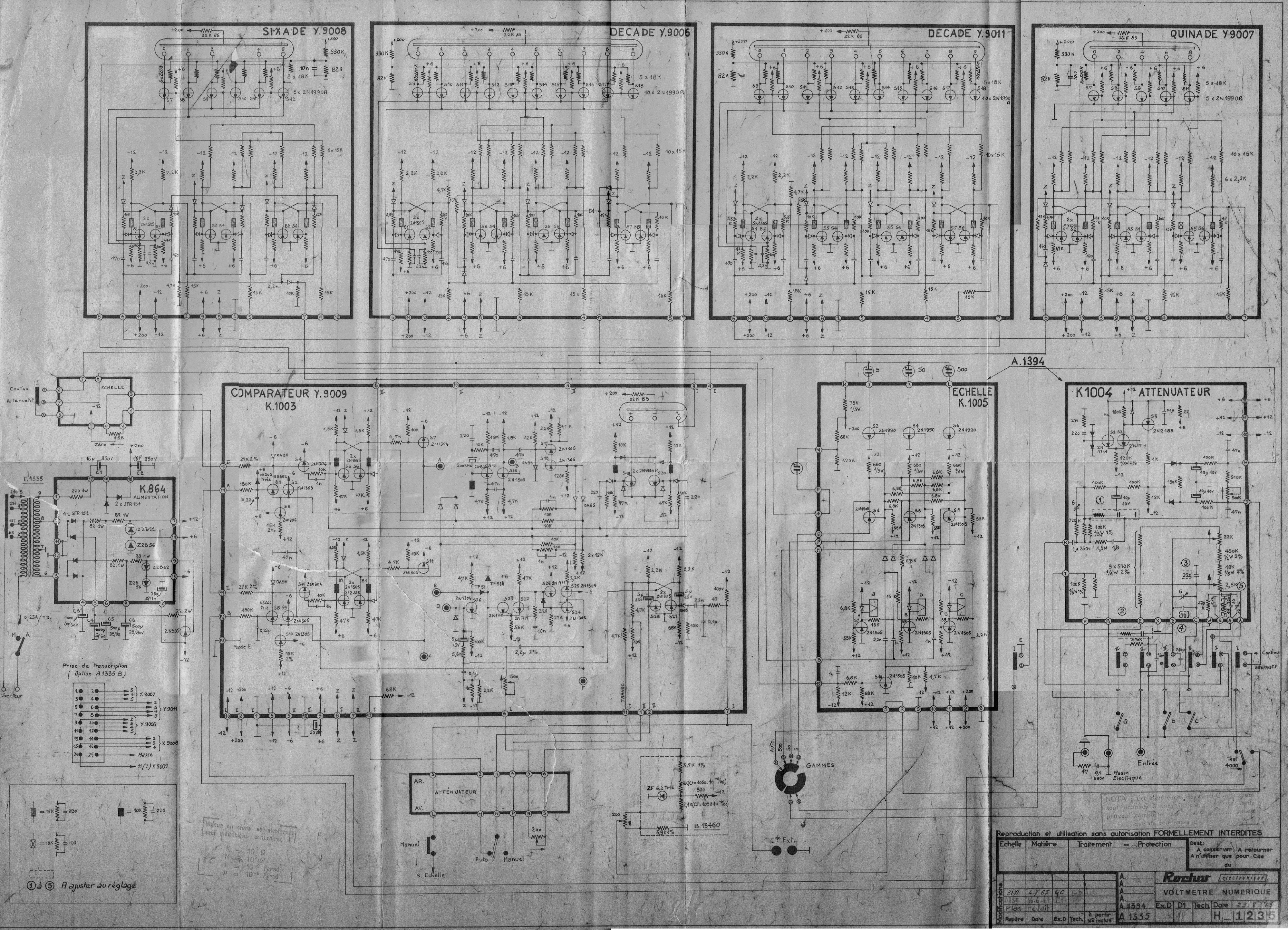
I also had to sort out the wires. Some had damaged insulation and needed replacing, others were broken off. Some paths were cut and the connections changed with wires, other paths are not there at all, just a crossover of wires. Fortunately I have a schematic (it's attached) and I was able to compare the unit I have to this schematic. This schematic shows the mass-produced version from 1965 onwards, with corrections made in 1967. This is the original scan, poor, but I don't have a better one.
I was already able to fit the transformer and power supply board. The power supply still needed to replace the 2N555 germanium transistor that stabilises the -12V voltage. I replaced it with a much stronger 2N1558 transistor and added a new resistor (the original one was burnt out).
The power supply is ready, it passed the load test, there are correct voltages on all connectors, it's good!
Note: I added a resistor and a Zener diode to the power supply to limit the supply voltage to the NIXIE tubes to 180V. This is a little low, but the tubes work OK. In this voltmeter the digits in the tubes are controlled by old 2N1990 transistors, for which the catalogue Uce is only 60V. The LC531 tube ignition voltage is about 160V, while the quench voltage is above 110V. The difference of Uce=60V when the transistor is open and plugged is sufficient to ensure proper lamp operation. However, if the mains voltage went up (which happens, due to the photovoltaics), without stabilisation the NIXIE supply voltage would increase and the inactive digits might not go out properly. I also added a 14V transil in the -12V path to protect the modules in case of a power supply failure (there are very old 2N1305 germanium transistors in the modules) I also replaced the power supply socket and made ventilation holes so that the counter modules would not overheat.
Note: I run vintage devices through autotransformers that reduce 240V AC to 220V (that's the voltage I have in the mains, 238V with jumps to 246V). Some old appliances designed for 220V cannot handle 240V. While I have never had an electrolytic capacitor explode, it is common for series power supplies to overheat and even for the transformer core to saturate when the mains exceeds 245V (blowing a fuse). I used to think of making a separate 220V AC mains in one room, with Schuko plugs without a grounding pin hole, so as not to confuse it with the 240V mains.
Another item - NIXIE lamps. The original American Burroughs B5031 were fitted to this unit (later serial models had French CSF F9057 lamps manufactured from 1963 onwards). Unfortunately in my voltmeter the tubes were damaged (some digits burnt out).
Fortunately the Polish LC513 tubes fit perfectly:
Comparator: Already at first glance it needed repair, or rather tidying up of some components. Due to the fact that this is a prototype version some paths were cut and components were placed in newly drilled holes and connected by wires. It looked like a nightmare, but I managed to embrace it. There was another problem - some of the contact pins were falling out of the boards. All contacts to be removed and reassembled: (the serial version of this voltmeter has good gold-plated pins and sockets)
Dividers: The voltmeter contains 4 transistor dividers. These dividers are not prototypes, they have been manufactured by Rochar before for fuel flow meters and later for frequency meters, so there is no mess with cut paths. The only thing that has been added are the leads for the automatic range switching signal (additional diodes).
Counting from the input side of the 200 kHz signal, the first divider divides by 5, the next two by 10 and the last by 6. So the largest displayed value can be 5998 (the last digit of the result can only be even). Apparently Charbonnier decided that the accuracy of the A.1335 measurement was so low that it was not worth fitting a full decade (transistors were very expensive in those years, especially the 'high voltage' ones at 60V).
Startup - voltmeter not working!
Random digits are displayed, the instrument does not measure voltage. To fix this monument let's look at the principle of its operation: This voltmeter has no integrator (the Solartron LM1420 already had an integrator). The A.1335 has a pulse-timing circuit. Simplified block diagram with range change automation omitted:
Operating principle:
The measuring system can be triggered manually with a push button (one measurement) or automatically from a 2 Hz generator. Immediately after triggering, the counters are reset and the flip-flop opens the gate and pulses from the 200 kHz quartz generator are applied to the counters, which count them by flashing for a while (no latch). At the same time, the 'ramp' formation circuit is activated, which feeds a linearly rising voltage to the comparator depending on the time constant of the RC circuit with a 2.2 uF capacitor. When the "ramp" voltage exceeds the measured voltage, the comparator switches the flip-flop, which closes the gate and the displays show the measured result. Another cycle can be started by pressing a button, or the automaton will repeat the measurement every half second. Seemingly simple, but building this without digital integrated circuits, on old germanium transistors is a masterpiece.
There is so much theory, but in practice:
The 200 kHz quartz generator works, the gate opens, but the first quinada does not count correctly! (quinada is a word invented by Charbonnier, he liked to create his own words to name his circuits, sometimes he also created his own symbols). Let's look at the schematic of this divider: Three flip-flops configured to divide by 5 and a simple driver on 5 transistors.
What's broken: a faulty (open) diode at the collector of transistor S1 prevents the reset signal from being applied! Replacement of the diode and it is OK.
But not quite, the second module, the decade, is also broken. This module contains 4 flip-flops. The first one divides by 2, the next three are configured to divide by 5. Just like the well-known 7490 counter. The first flip-flop has another function: by alternating the polarity of the emitters, it controls a transistor decoder displaying alternating even and odd digits, thus correctly selecting one of the 10 digits (the quinada does not have this decoder, the emitters of the transistors controlling the NIXIE tubes are shorted to ground).
The diode feeding the signal to the range automation control was faulty, it was shorted and the decade display was wrong and dividing incorrectly. After replacing the diode the meter started up correctly, the voltmeter displayed a stable result!
Interesting fact: some mass-produced copies of the A.1335 had outputs to the printer in BCD code. The version I have repaired does not have such an output, although the decks have pins in BCD code, which can be used to control, for example, the CD4056 decoder and modern 7-seg displays.
Unfortunately, the voltmeter repaired in this way only worked on one range. The other ranges did not work, so I had to deal with the range-switching circuitry. The A1335 ranges can be switched manually, or the automatic can be switched on. The automatic did not work, manual switching only activated one range. In addition, the equipment measured badly, although the result was stable.
Here is the range switch board with a description of the control elements: (the white connector visible in the photo is not original, I inserted it for ease of board removal)
and this is the automation board:
I checked the components on the boards, they were OK. However, there are 4 large reed relays between the boards (not visible in the photo). The reed switch in one of them was broken:
In addition, the rotary switches, which nobody had used for more than 30 years, needed cleaning.
After replacing the reed switch and cleaning the switches, the voltmeter started up on all ranges, but the readings were not correct. On the underside of the unit there is a voltage reference - a 6.2V reference diode (small black element) and resistors, including two precision resistors. A couple of resistors were faulty, fortunately the precision 1200 Ω and 4 kΩ resistors are OK. I replaced the resistors with Polish RMGs. I still had to glue the calibration voltage setting potentiometer visible in the photo, because the lid fell off.
Commissioning for the second time:
The device is working properly, it even managed to calibrate it. Automatic range switching also works.
All that remains is the refurbishment of the housing. Cleaning of rust, painting, pasting of plexi etc. It was very difficult to keep the original colour, custom mixed paint. But I will not describe it here.
Measurements:
DC voltage measurement in the video below. As you can see it's not too bad, equipment that is over 60 years old measures correctly, better than many of today's cheap microprocessor multimeters.
And the alternating voltage? Here it is no longer simple, nor so beautiful. Where to get an AC voltage standard from? I don't have an AC calibrator, the HP3325A broke down (when I fix it, I'll make another measurement), so I used an Adret 2230A generator, which used to be used to test telephone lines. This generator was once even calibrated, so maybe it won't be too bad. I loaded the 75 Ω output with two 150 Ω resistors connected in parallel. For voltage monitoring, I attached a Solartron 7140 voltmeter.
The Rochar A.1335 measures reasonably correctly up to 10 kHz. Measurement on the second video, 4 signal levels: +12dBm, +10dBm, 0dBm, -10dBm for frequencies 100Hz, 1kHz, 10kHz, 100kHz. Admittedly, above 10kHz the result is inaccurate, but for a vintage design it is fine. Another monument saved!
Regards, M.S.
PS. this is what the creator of this device looked like:
He designed all his constructions himself, without the use of a computer, on a piece of paper, thanks to the genius of his mind. I have only saved one of his first ideas from oblivion. Today are different times, electronics have changed. In an age of widespread microprocessors, transistor dividers may be laughable, but such were the beginnings, and I think it is worth preserving for posterity a history that will never return.
Attachments:
Rochar_A1335_AC.mp4(13.82 MB)
You must be logged in to download this attachment.
Rochar_A1335_DC.mp4(3.2 MB)
You must be logged in to download this attachment.
Rochar_A1335_schemat_1965.png(12.09 MB)
You must be logged in to download this attachment.
About Author
sq2aki wrote 31 posts with
rating 163 .
Live in city Bydgoszcz.
Been with us since 2008 year.
Wow nice voltmeter and nice description. I'm always fascinated by devices made without ICs on transistors alone. I haven't come across the voltmeter yet, so thanks for presenting it. [Read more]
Krzysztof Kamienski
23 Nov 2025 00:22
Solartons operated at the Warsaw University of Technology until the 1990s.
A beautiful instrument and a beautiful owner in the first photo. All in all, bravo! Perhaps someone from the Old Engineering... [Read more]
rafi8112
23 Nov 2025 01:38
Many congratulations! I really like the idea of refurbishing old appliances, giving them new life. I love this kind of atmosphere. [Read more]
Olkus
23 Nov 2025 13:42
Congratulations on your restoration. You can see the enormous amount of work you have put in.
Regards,
A. [Read more]
predom
23 Nov 2025 15:38
Sensational work, I'm really impressed with both the end result and the knowledge to understand how the instrument works and to diagnose and fix all the faults. It's good that such a unique gauge ended... [Read more]
acctr
23 Nov 2025 19:24
The meter was lucky because it ended up in good hands and now as a whole it looks great.
The electronics from a different era, as you can see from the schematic and the transistor symbols. The principle... [Read more]
kris8888
24 Nov 2025 00:55
Well, rather not, because the ICL7106/7 is an A/D converter with double integration and here we have only a simple converter counting pulses from a reference generator, in time proportional to the value... [Read more]
sq2aki
24 Nov 2025 10:12
Actually, in one lamp the odd digits are "poisoned" - this lamp was working in a quinade that only displayed the even digits. When I find time, I'll try to carry out an activation of these digits, maybe... [Read more]
kris8888
24 Nov 2025 15:03
It is fascinating that in such an old voltmeter an automatic range change was thought of and cleverly designed. Admittedly, I can't quite work out how it works, a bit because of the unusual markings on... [Read more]
acctr
24 Nov 2025 18:43
I can see the similarity there - in both cases the displays are controlled by a counter, which de facto presents time in some function of voltage, and in both cases there are two HI/LO measurement inputs.... [Read more]
OTLamp
24 Nov 2025 21:36
But not on relays alone. There were also some electron tubes. It was a compensating voltmeter, the easiest to make at the time and the cheapest. For that it was fully automatic, it had basically just a... [Read more]
kris8888
24 Nov 2025 21:53
And indeed. I didn't even know there were that many.
I guess that in addition to vintage receivers you must have started collecting old measuring equipment.... [Read more]
OTLamp
24 Nov 2025 22:04
In fact, for about a dozen years now. But only digital and as old as possible. Unfortunately those from the 1950s are both very rare and very expensive. When some NLS comes out once every few years, you... [Read more]
sq2aki
24 Nov 2025 22:54
Can such a hermetic electromechanical selector even be repaired?
https://obrazki.elektroda.pl/9934185000_1764020681_thumb.jpg
It works, or rather it worked in a Marconi TF2603 voltmeter. It was... [Read more]
Krzysztof Kamienski
24 Nov 2025 23:00
@sq2aki It's not so much a selector as a vibrator. There used to be such instead of transistor keys in power supplies for mobile tube devices e.g. car receivers or military radios. [Read more]
OTLamp
24 Nov 2025 23:21
This is not a selector. You have the selector in one of the videos above. It takes the form of a rotary switch with a ratchet mechanism driven by an electromagnet.
Your component, on the other hand, is... [Read more]
Krzysztof Kamienski
24 Nov 2025 23:41
@otlamp Old pehammeters, ionisation chambers radiation detectors etc. [Read more]
kris8888
24 Nov 2025 23:42
It might be better with some suitably sized optocoupler? [Read more]
Krzysztof Kamienski
24 Nov 2025 23:57
@kris8888 Namesake, first find out what is e.g. an electrometric amplifier with DC/AC processing" , what it is characterised by and then propose solutions. [Read more]
FAQ
TL;DR: Restoring a Rochar A.1335 (max display 5998) means taming a 200 kHz pulse‑timing DVM; “equipment that is over 60 years old measures correctly.” [Elektroda, sq2aki, post #21759194]
Why it matters: This FAQ helps vintage‑test‑gear fans diagnose, calibrate, and sympathetically upgrade early European digital voltmeters without erasing their history.
What makes the Rochar A.1335 historically interesting?
It is among Europe’s earliest digital voltmeters. A prototype existed in 1962; the catalog model followed in 1964. It uses a pulse‑timing method and early NIXIE display drivers built from germanium transistors. The restored unit was a prototype without a serial number. [Elektroda, sq2aki, post #21759194]
How does the A.1335 actually measure voltage?
It counts 200 kHz clock pulses while a linear ramp climbs until it exceeds the input voltage. A comparator stops the gate, and the counters show the result. There is no integrator or latch; displays flash during counting. "Seemingly simple…a masterpiece" without ICs. [Elektroda, sq2aki, post #21759194]
Why does the display top out at 5998 and why are last digits even?
The chain is /5, /10, /10, /6. That makes the top reading 5998, and the final division by two yields only even least‑significant digits. Charbonnier optimized parts count when high‑voltage transistors were expensive. [Elektroda, sq2aki, post #21759194]
Is the A.1335 a True RMS voltmeter?
No. With a 2 Vpp setting, it reads correctly only for sine waves. Its AC front‑end is a simple converter. Measured performance is reasonable to ~50 kHz but shape‑dependent, so non‑sine waveforms read off. [Elektroda, sq2aki, post #21764145]
What are common power and NIXIE supply pitfalls?
Electrolytics dry out and wiring insulation cracks. Add a resistor and Zener to hold NIXIE supply near 180 V, since the 2N1990 drivers are rated Uce 60 V. Overvoltage can leave inactive digits faintly lit. [Elektroda, sq2aki, post #21759194]
How should I power up a vintage DVM safely?
Never plug straight into mains. First isolate and test the transformer for shorts and insulation. Use an autotransformer to reduce 240 V to ~220 V. High mains can overheat series supplies or saturate the transformer and blow fuses. [Elektroda, sq2aki, post #21759194]
The display shows random digits. Where do I start?
Check the first divider (quinada). A single open diode on the S1 collector blocked reset. In the next decade module, a shorted diode upset division and display. Replacing the diodes restored stable counting. [Elektroda, sq2aki, post #21759194]
How does auto range switching work, and what fails?
Range logic drives reed relays and rotary contacts between switch and automation boards. A broken reed capsule and oxidized rotary wafers prevented ranges from engaging. Replacing the reed and cleaning contacts restored all ranges. [Elektroda, sq2aki, post #21759194]
What is “quinada” in this context?
It is Charbonnier’s coined term for a divide‑by‑five stage built from three flip‑flops and a transistor driver. In the A.1335 the first stage is a quinada feeding downstream decades. [Elektroda, sq2aki, post #21759194]
Can I rejuvenate NIXIE tubes with missing segments?
Yes, if the issue is cathode poisoning. Raise voltage so dark portions just light, and limit current to about three times rated. "Chew" each digit for hours until emission returns, repeating across digits. This saved LC‑531 and IN‑12 tubes. [Elektroda, predom, post #21759928]
What is a chopper amplifier in older meters?
A chopper periodically switches tiny DC signals, converting them for stable amplification while minimizing offset and drift. Specialized contact materials and shielding matter more than current rating. It differs from car vibrators. [Elektroda, OTLamp, post #21761393]
My Marconi mechanical chopper is worn out. Is there a solid‑state retrofit?
Yes. Marconi’s 1984 service addendum shows a J‑FET chopper driven by a CD4011 module that substitutes the mechanical syncroverter. Matched J‑FETs like J112 are recommended for low‑level ranges. [Elektroda, sq2aki, post #21761636]
Did early DVMs auto‑range, and did Polish meters have it?
Yes. Auto‑range was common in first‑generation DVMs. Polish examples include CEMI’s AMS3 and Meratronik models V542, V545, V553, and V563. [Elektroda, OTLamp, post #21761267]
Were Weston cells used as the reference inside early digital voltmeters?
No. Weston cells served calibration and adjustment, not as internal references. Polish Elpo V523/V524/V527/V529 compensating meters and the V552 had cells for that purpose. [Elektroda, OTLamp, post #21761267]
How accurate is AC at high frequency on the A.1335?
Catalog AC specs are optimistic at the top end. At 200 kHz, measured error exceeded 2% versus a 1% catalog claim. The simple converter limits true high‑frequency accuracy. [Elektroda, sq2aki, post #21764145]
How do I perform a safe first power‑on and basic stabilization tweak?
Test transformer off‑circuit, then recap and rewire per the 1960s schematic.
Bring up on an autotransformer, monitoring rails and NIXIE supply.


Comments
Wow nice voltmeter and nice description. I'm always fascinated by devices made without ICs on transistors alone. I haven't come across the voltmeter yet, so thanks for presenting it. [Read more]
Solartons operated at the Warsaw University of Technology until the 1990s. A beautiful instrument and a beautiful owner in the first photo. All in all, bravo! Perhaps someone from the Old Engineering... [Read more]
Many congratulations! I really like the idea of refurbishing old appliances, giving them new life. I love this kind of atmosphere. [Read more]
Congratulations on your restoration. You can see the enormous amount of work you have put in. Regards, A. [Read more]
Sensational work, I'm really impressed with both the end result and the knowledge to understand how the instrument works and to diagnose and fix all the faults. It's good that such a unique gauge ended... [Read more]
The meter was lucky because it ended up in good hands and now as a whole it looks great. The electronics from a different era, as you can see from the schematic and the transistor symbols. The principle... [Read more]
Well, rather not, because the ICL7106/7 is an A/D converter with double integration and here we have only a simple converter counting pulses from a reference generator, in time proportional to the value... [Read more]
Actually, in one lamp the odd digits are "poisoned" - this lamp was working in a quinade that only displayed the even digits. When I find time, I'll try to carry out an activation of these digits, maybe... [Read more]
It is fascinating that in such an old voltmeter an automatic range change was thought of and cleverly designed. Admittedly, I can't quite work out how it works, a bit because of the unusual markings on... [Read more]
I can see the similarity there - in both cases the displays are controlled by a counter, which de facto presents time in some function of voltage, and in both cases there are two HI/LO measurement inputs.... [Read more]
But not on relays alone. There were also some electron tubes. It was a compensating voltmeter, the easiest to make at the time and the cheapest. For that it was fully automatic, it had basically just a... [Read more]
And indeed. I didn't even know there were that many. I guess that in addition to vintage receivers you must have started collecting old measuring equipment.... [Read more]
In fact, for about a dozen years now. But only digital and as old as possible. Unfortunately those from the 1950s are both very rare and very expensive. When some NLS comes out once every few years, you... [Read more]
Can such a hermetic electromechanical selector even be repaired? https://obrazki.elektroda.pl/9934185000_1764020681_thumb.jpg It works, or rather it worked in a Marconi TF2603 voltmeter. It was... [Read more]
@sq2aki It's not so much a selector as a vibrator. There used to be such instead of transistor keys in power supplies for mobile tube devices e.g. car receivers or military radios. [Read more]
This is not a selector. You have the selector in one of the videos above. It takes the form of a rotary switch with a ratchet mechanism driven by an electromagnet. Your component, on the other hand, is... [Read more]
@otlamp Old pehammeters, ionisation chambers radiation detectors etc. [Read more]
It might be better with some suitably sized optocoupler? [Read more]
@kris8888 Namesake, first find out what is e.g. an electrometric amplifier with DC/AC processing" , what it is characterised by and then propose solutions. [Read more]