
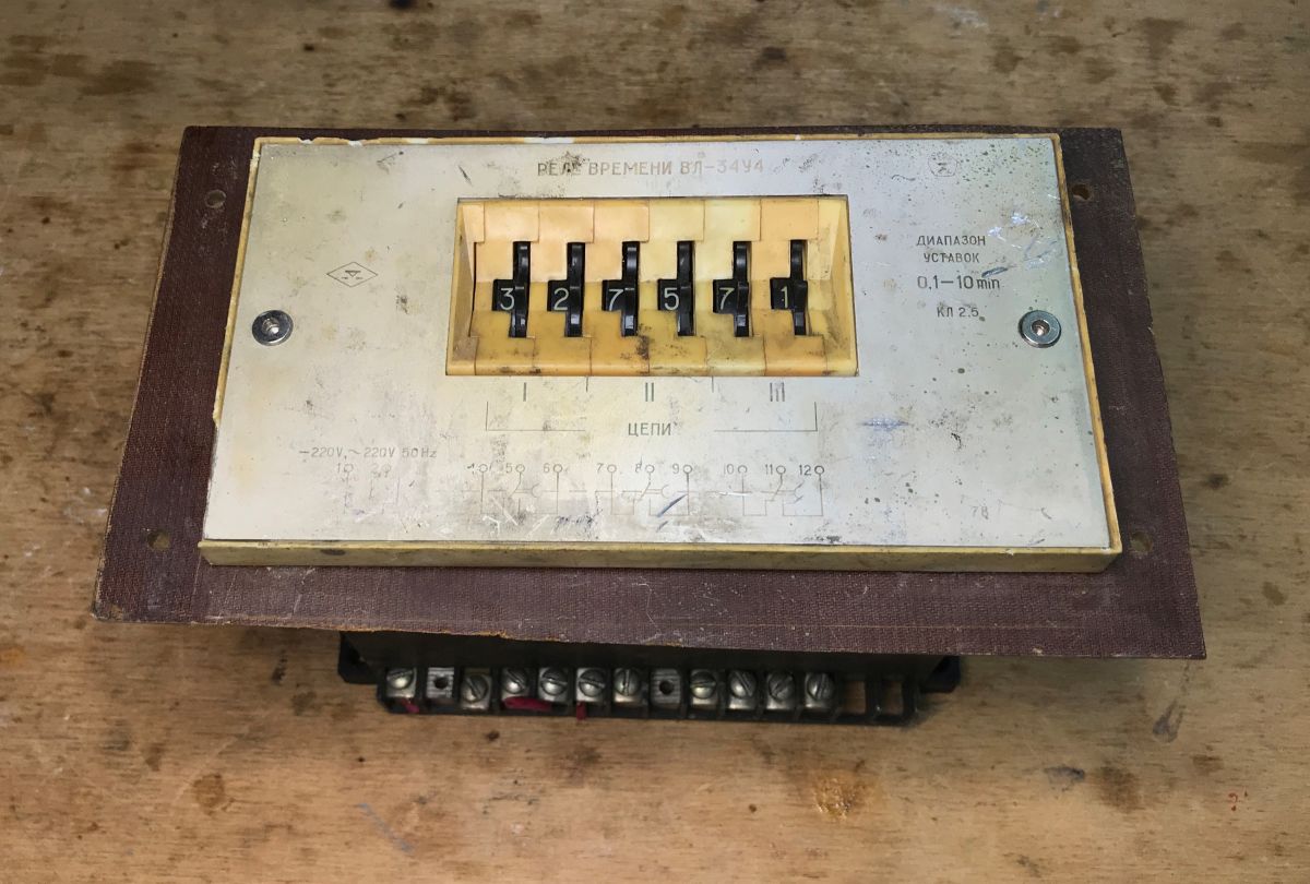
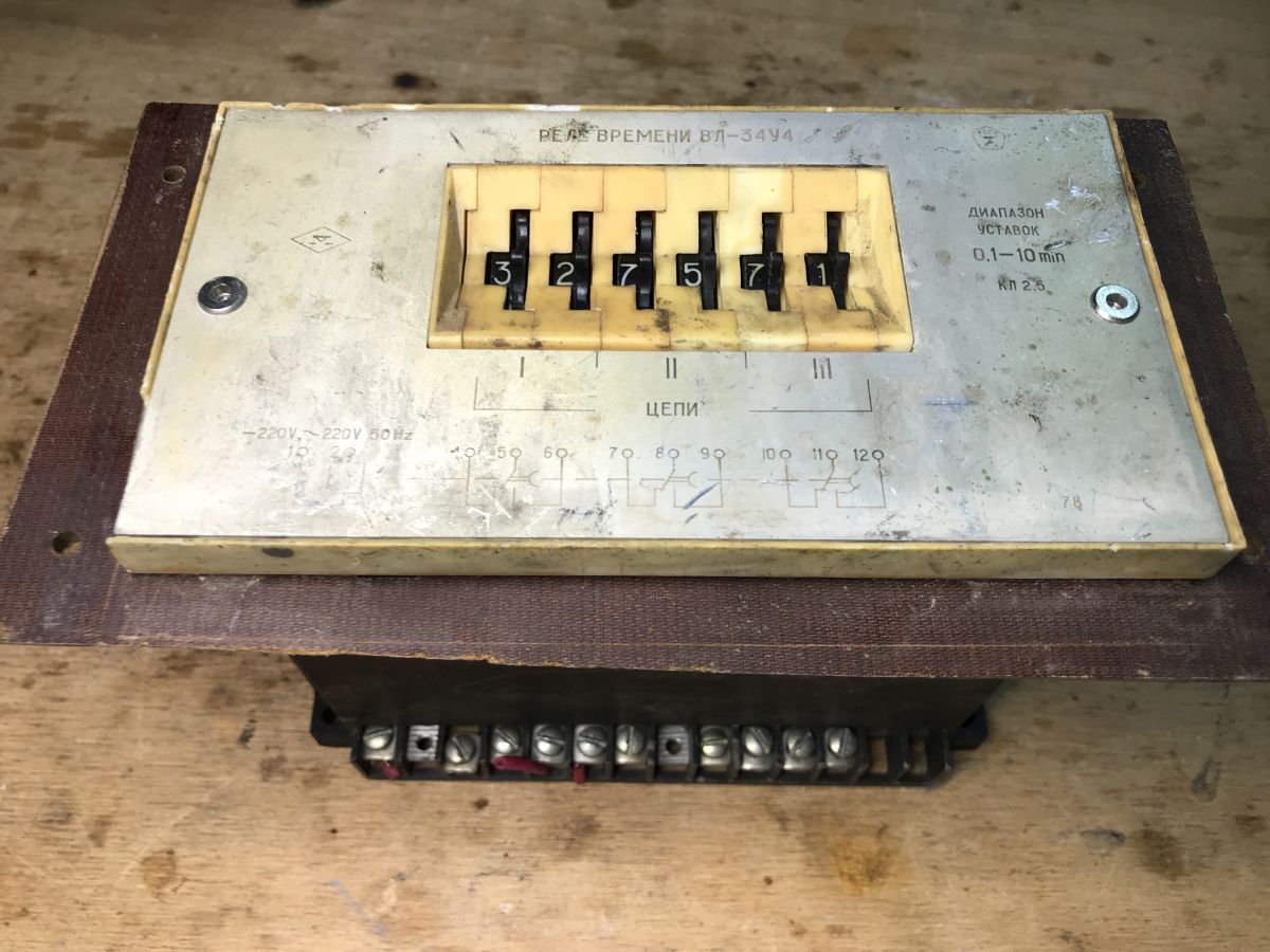
Here’s a little curiosity for today. This piece of kit is completely outside my field of expertise and not from my era, but it might still be worth a look – an old triple timer dating back to the days of the USSR. The whole thing is built using semiconductors. Time to take a look inside.
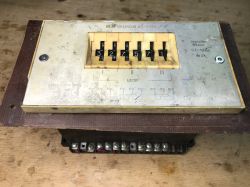

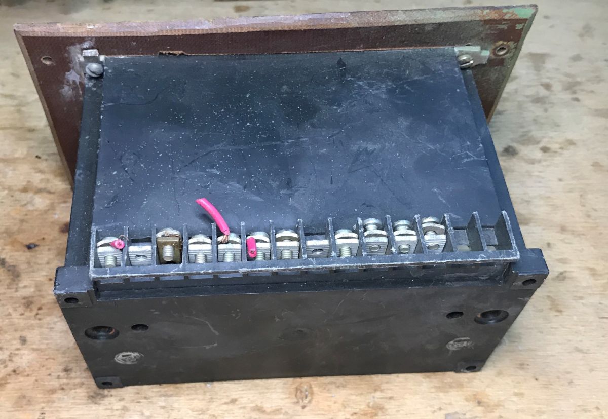
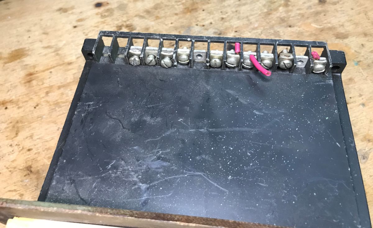
On the front panel, we can set three separate relay switching times. Just below, there is a diagram showing the internal connections and indicating which terminal screw is the common contact, normally open and normally closed. Let’s take a look inside:

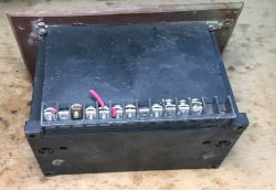
Inside, we can see three separate relays and two control boards. On one of them is a potentiometer protected by paint, presumably for tuning.


What surprises me most, however, is the size of the components. The relays there bear no resemblance to today’s compact solutions. Overall, there is also much more mass, and consequently more raw material.


Progress with dismantling and part number from the circuit board - C67.102.280:


Dismantling of the board, on which a rectifier bridge, a large electrolytic capacitor and characteristic resistors can be seen. Although the time setting itself is mechanical, the counting is already carried out by a semiconductor.


There is no label layer on the board, and all tracks are tin-plated for durability.


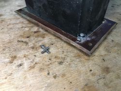
Removing the front panel and separating the mechanical components:


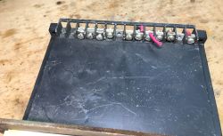
Removing the relays:


Removing the meter module:


It is implemented using the K176TM1 and K176NE5 integrated circuits. I am curious about the component next to the potentiometer – is that a resonator from that era?


I also wanted to check how the time is set, but the dismantling was interrupted due to the flood in 2024 and I did not complete the analysis, and the circuit board was lost. From what I remember, however, there were separate contacts for each pin, rather than a single resistive track.
I found a similar device on this website:
https://dzen.ru/a/X70JlQtK-AFJrFkT
I had originally planned a more detailed presentation, including a schematic diagram, but the 2024 floods thwarted those plans and the equipment did not survive the clean-up.
Therefore, I would be grateful for any additional information if anyone is able to identify the correct operating principle and the roles of the components inside?


Comments
Nothin' but nuthin' but nuthin' design :) MŁT resistors and relays without a case with the windings protected by a material soaked in some kind of impregnation. Typical Soviet rectifier diodes and... [Read more]
There is also the K176LE5, 4xNOR. The correct name for this chip with a generator in the Latin alphabet is K176IE5 rather than "K176NE5", which makes it easier to search for. [Read more]