
I invite you to a little adventure with the PIC16LF1459, an 8-bit microcontroller made by Microchip, distinguished by its hardware USB support with a minimum of external components. You don't even need an external oscillator - the built-in one has enough precision. Here I will run USB communication on it using the free SDCC compiler, all without external libraries. I will show here examples of HID applications, such as simple LED control, data exchange using a simple 'maths coprocessor' as an example, and then show how to realise practical HID-compatible devices - a mouse and a keyboard.
A proper tutorial on SDCC:
Tutorial PIC18F2550 + SDCC - Part 1 - Setting up the operating environment
A few words about the PIC16LF1459
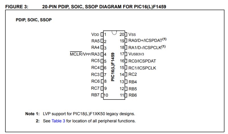
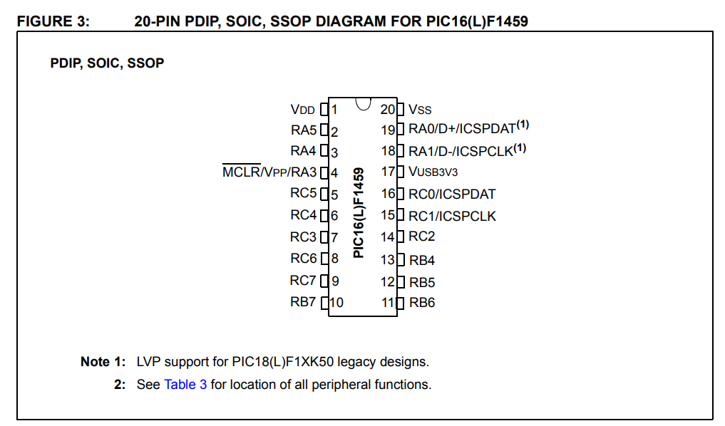
The PIC16(L)F1459 is an 8-bit microcontroller based on a RISC core by Microchip. It has 14 KB of Flash memory and 1 KB of RAM. Depending on the version, it can operate at 1.8 - 3.6 V (L version), and at 2.3 to 5.5 V. It is distinguished by hardware USB (compatible with USB Low and Full Speed - up to 12 Mbps) based on a 512-byte shared memory buffer. Among other things, the PIC16LF1459 is available in a hobbyist-friendly DIP package.
 Connecting to the PIC
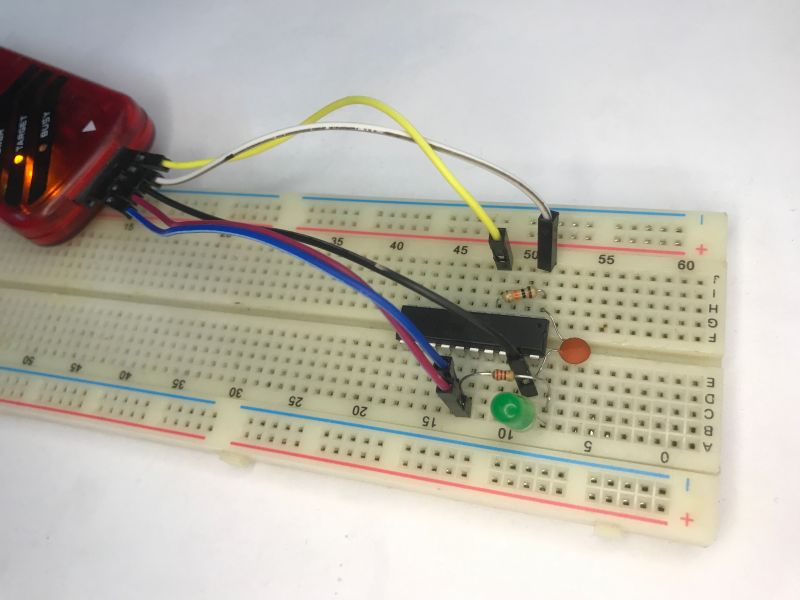
The PIC shown requires a very small number of components to run. Basically you need to give a 100 nF decoupling capacitor between the power supply pins, this is for the principle, as in any microcontroller, and a 10 kΩ resistor between the MCLR pin and the power supply - this to get the PIC to boot, shorting MCLR to ground resets the circuit.
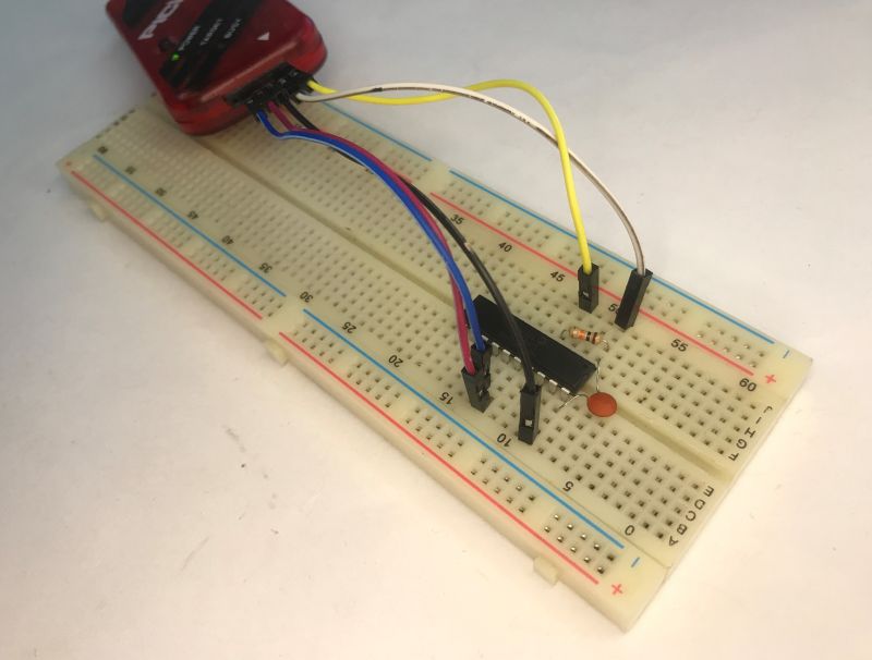
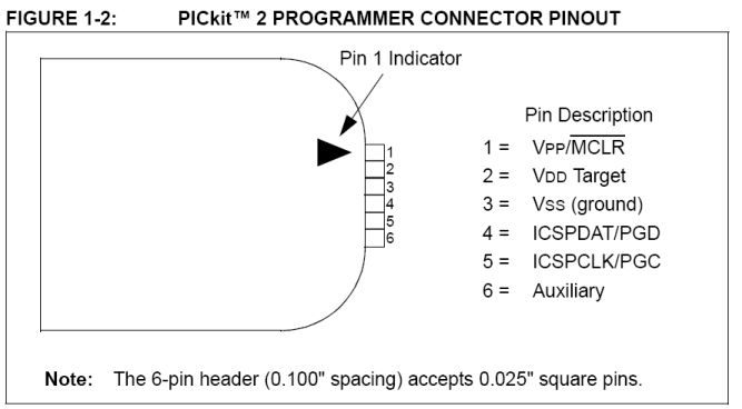
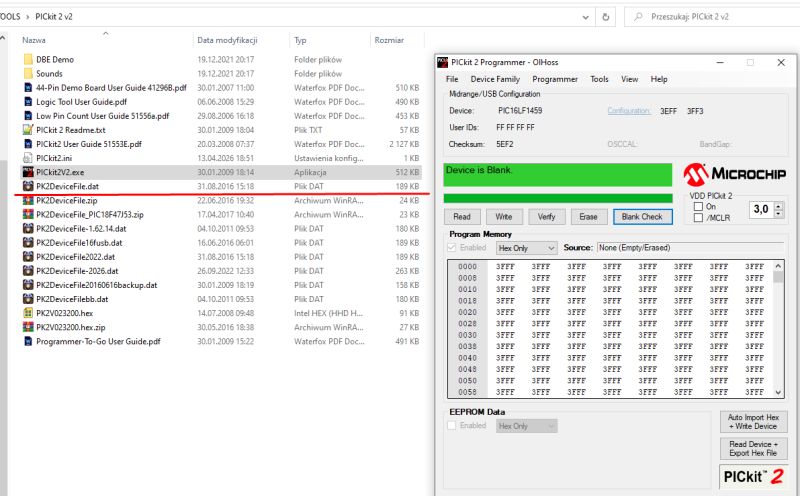
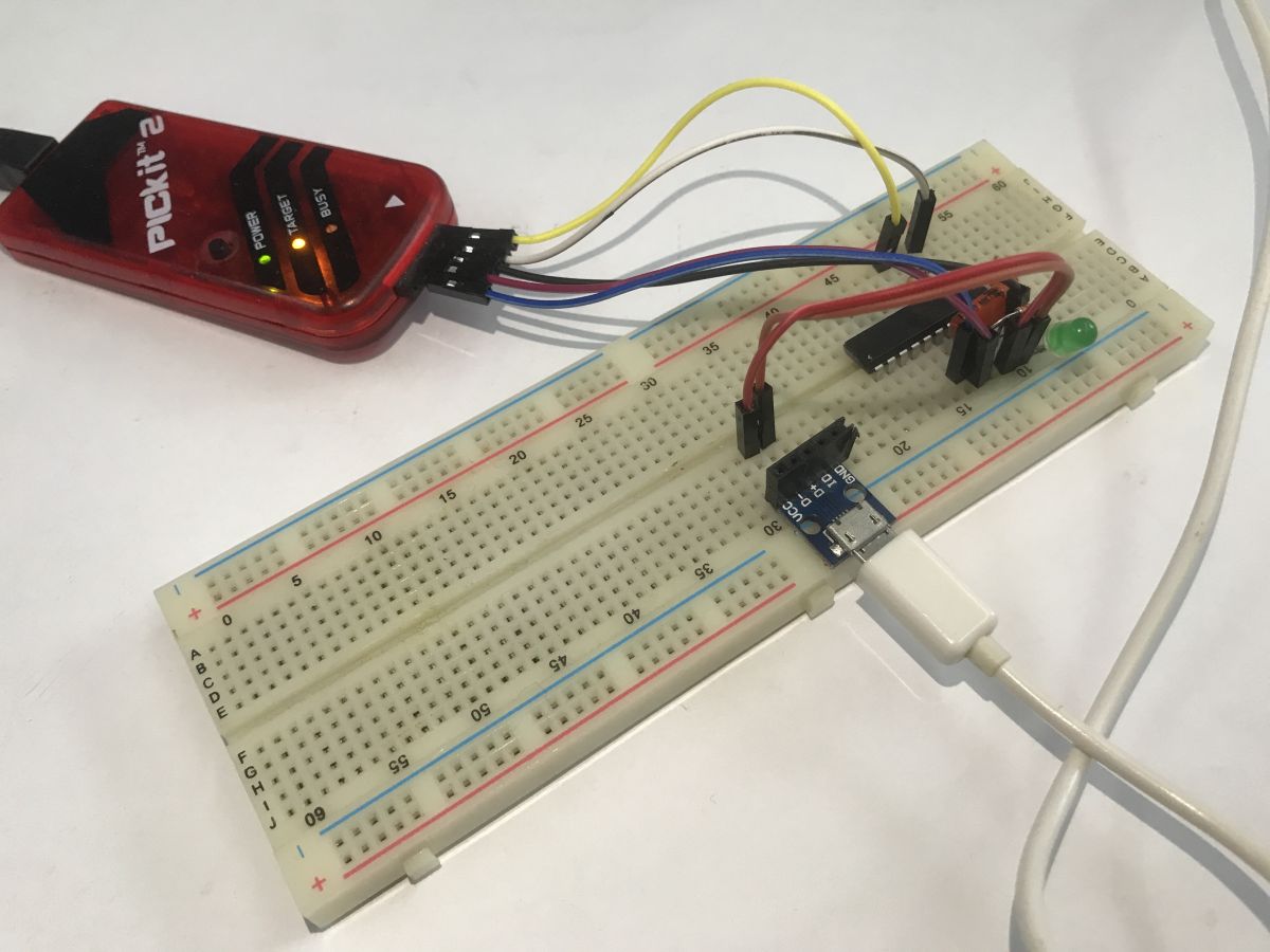
The PICKIT3 is suitable for programming, although with the new Device File even the PICKIT2 can handle it. We program via ICSP:
I posted the Device File for PICKIT2 in my older topic about this PIC. There I was still running it with a commercial microC, for that reason I think the solution presented today is a big step forward.
PIC16F1459 boot board with USB
PICKIT2 handled this PIC with no problems at my place:
 Hello World - Blink LED
Blink LED is often the first program I run on microcontrollers. It allows me to check that the batch starts at all and that it works at least somewhat stably.
The program starts the PIC with the built-in resonator, the OSCCON register is used to configure it. I then configure the entire C port as an output, and flip its state to the opposite state in a loop. The function waiting 1000 ms is a simple blocking loop. In the target program this shouldn't be there, as it just wastes CPU cycles, but for a test it's acceptable.
Now just connect the LED and resistor to any pin from port C:
Basically that's it - the LED flashes:
 Simple USB - LED control via HID
Now we come to the actual USB part. I'll start with the LED control. I'll put all the code in the appendices, although I won't go quite into the theory that is "under the hood". Still first the connection - I used the USB breakout board for this:

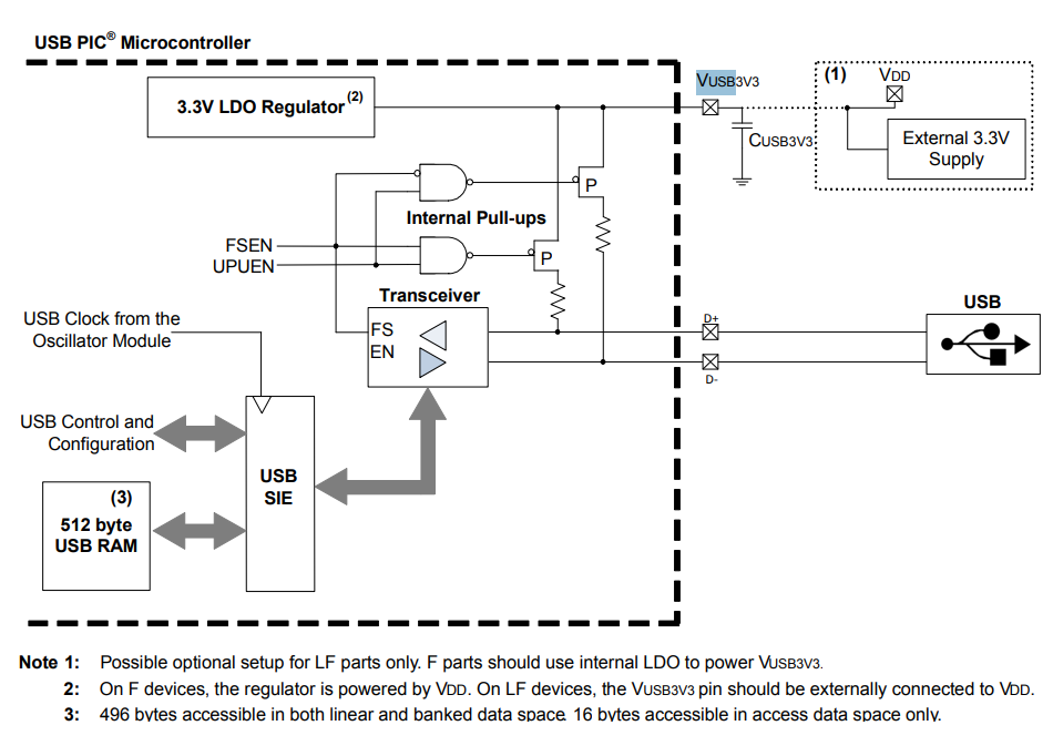
Overall, running USB on the PIC16LF1459 in the SDCC compiler requires proper configuration of the registers responsible for this module and defining basic descriptors for the device, configuration and interface in the HID class. Hardware-wise, the PIC relieves us to a large extent, e.g. with the Active Clock Tuning (ACT) function, which, through continuous synchronisation to USB frames (SOF), allows a stable 48 MHz from the built-in internal oscillator, but we have to program the descriptors ourselves. In the C code itself, handling the diode control is reduced to intercepting SET_REPORT requests on the control endpoint (EP0) and reading the sent data byte. To connect to such a configured device on the computer side, we can use a short script in the system Python based on the HID library, which, due to the use of the standard HID class, works "out of the box" and does not require the installation of any additional drivers in the operating system.
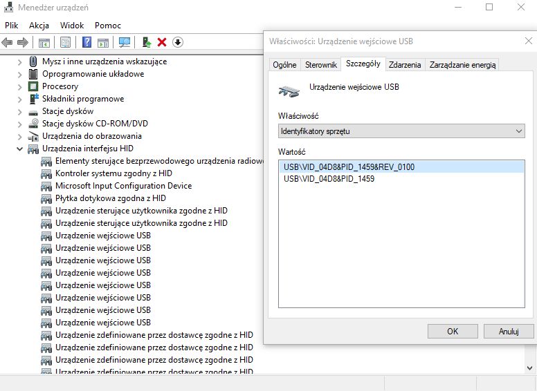
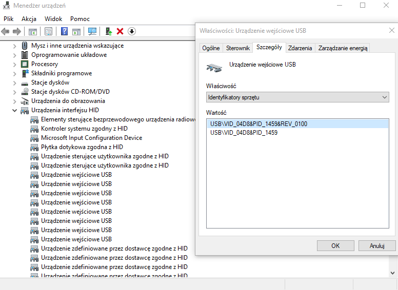
The most important parts - the descriptors, let's pay attention to Vendor and Product, by this we will know our device:
Transaction handling - state machine. The user is basically concerned here with parsing ep0out_buf, which is the HID frame buffer, it can contain more than one byte. We have simplified it for now.
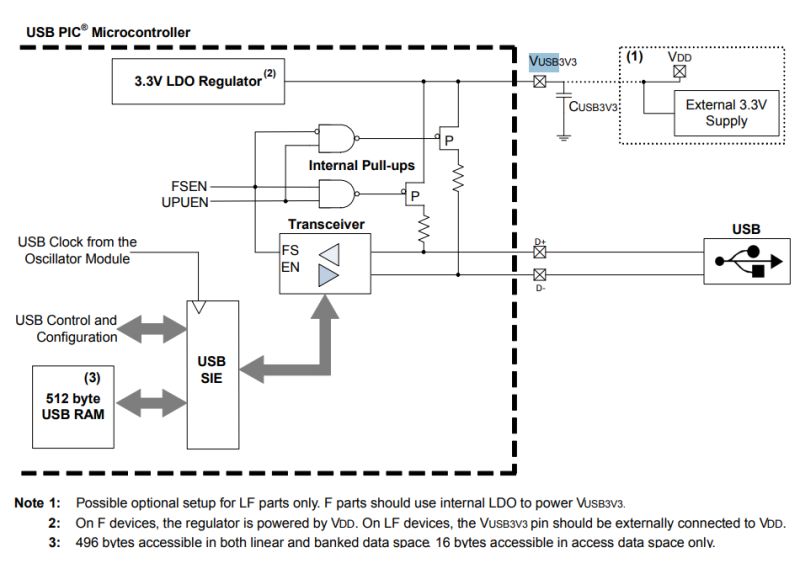
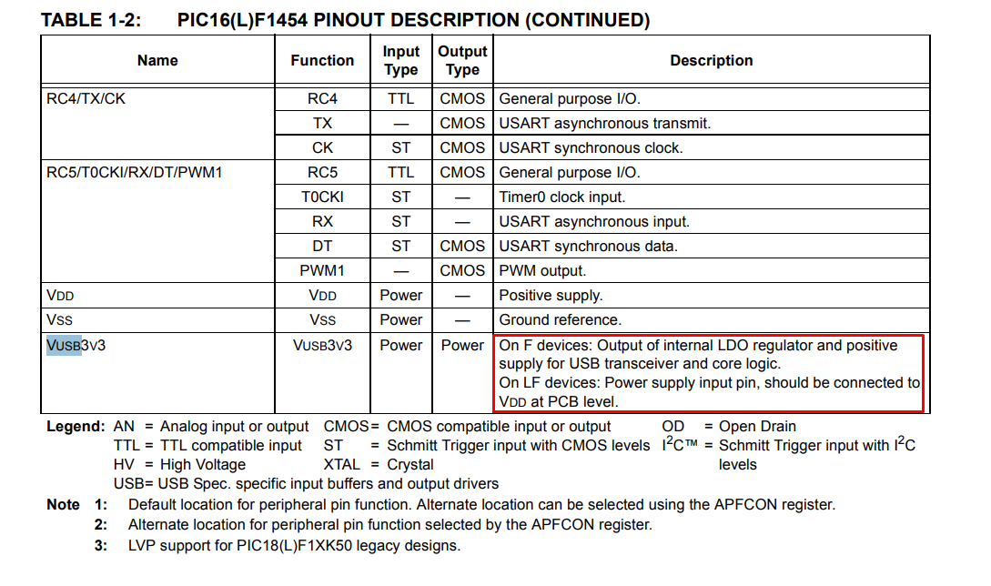
Hardware-wise we still need to remember the extra capacitor on Vusb (depending on the PIC version):
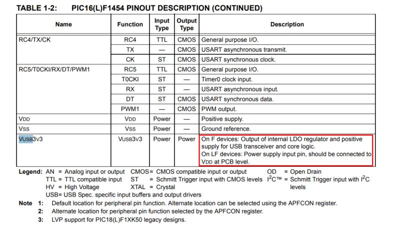
In the LF version we connect it to the power supply, otherwise a capacitor is needed.
This is enough for the PC to see the PIC:
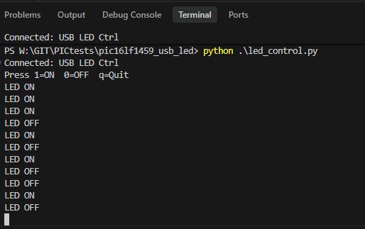
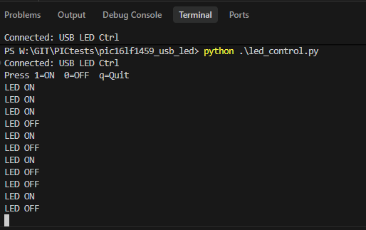
Now the PC program - for convenience in Python. A short script that finds the device by the entered Vendor/Product and sends this one byte over the HID to switch the LED:
The program works and the LED can be controlled.
 Packages USB HID - calculator
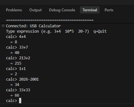
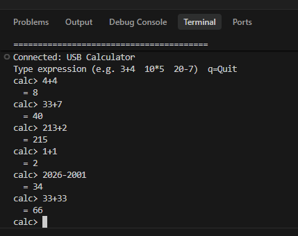
Let's further demonstrate for completeness the sending of a byte string. We can base this on the calculator example, the script sends a 2+2 style request and the PIC calculates this equation and returns the result. Such a mechanism requires two-way communication - the PIC has to receive the data, process it and then send back the result. A one-way message is not enough here, as with LED control.
So, receiving the data - processing it will be realised by the processIncoming function:
Sending the response - with the readiness flag attached (the program will then detect it and send the data on):
The heart of the calculator, i.e. parsing and calculations - the least important here, but for reference:
Result:
 USB HID device - mouse
A standard USB mouse is an HID device these days. This means that the code from the previous example, with very little change, can control the movement of the cursor on the computer screen. The first thing that is missing to fully simulate a mouse is device identification - the device must report in the descriptors as a mouse. You can at least look up the ID values in the documentation at Microsoft:
https://learn.microsoft.com/en-us/windows-har...dclass-hardware-ids-for-top-level-collections
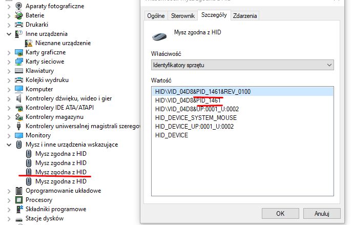
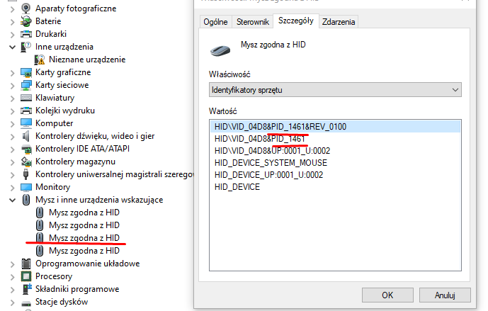
I have therefore completed the identifiers:
Windows has since recognised the PIC as a mouse:
Now the report still has to be sent. Windows rigidly expects the mouse to report, among other things, two bytes representing the cursor offset. All you need to do is send this via the HID, as in the previous example. For the example, I send the data resulting in a circular movement of the cursor. I didn't want to count trigonometry, so I generated an array resulting in circular movement:
Sending reports - looped index:
Generation of HID packet for mouse - format as expected by computer.
The result - the mouse does circles under any system, practical use is not there, but you can make a joke for someone.
 USB HID device - keyboard
Similarly - we look at the documentation and change the descriptors, the format of the data to be sent. In the HID Report Descriptor I changed the Usage Page to 0x01 (Generic Desktop) and Usage to 0x06 (Keyboard):
https://learn.microsoft.com/en-us/windows-har...dclass-hardware-ids-for-top-level-collections
In the Interface Descriptor I changed the protocol byte from 0x02 (Mouse) to 0x01 (Keyboard) - this tells the host at the interface level which device it is dealing with.
The format of the report also changed - the mouse used to send 3 bytes (buttons, deltaX, deltaY), the keyboard sends 8 bytes in the standard Boot Keyboard format:
Apart from this, under the hood I had to do a small fix - as the HID support is done without an external library, the response to the HID_SET_PROTOCOL request (0x08) was missing. The host sends this request to the boot protocol keypads to switch between boot and report mode - without a valid response (ZLP), the host could declare the device inoperable.
This leaves the main loop where I send the message:
Result:
 Summary
In summary, even a microcontroller as small as the PIC16LF1459 allows you to run functional USB communication without the use of heavy external libraries. Thanks to the built-in USB module, the ability to work with an internal oscillator and the Active Clock Tuning mechanism, it is possible to build a working device with a minimum of external components. The examples shown - from simple LED control, to data exchange in the form of a simple 'maths coprocessor', to mouse and keyboard emulation - show that implementing the HID class is relatively affordable, even when you implement most of the protocol handling yourself in code.
At the same time, it can be seen that the most work is required to prepare the correct descriptors and to handle the basic states of the USB protocol. Once this foundation is correctly implemented, however, further experimentation mainly boils down to processing the transmitted data and defining custom HID reports. This opens the way to building all sorts of simple USB peripherals - controllers, service tools or interfaces to communicate with your own projects.
Of course, you could also make a gamepad or joystick with multiple buttons and axes - maybe that's your next project?
The whole thing also shows that the free SDCC compiler is completely sufficient for working with this microcontroller and avoids closed, commercial environments. So, with a bit of patience, it is possible to create a fully working USB stack 'from scratch' and, in the process, get a good understanding of what actually happens under the hood of USB communication. This gives you a lot of freedom in designing your own HID devices and the ability to tailor the implementation exactly to the needs of the project.
Do you use HID communication in your own projects?
I attach the developed codes together with the compiled hex files.


Comments
Commercially it's called a 'mouse simulator / mouse jiggler', it more-or-less randomly moves the cursor so the computer doesn't go into sleep mode (which, depending on usage, can be more-or-less ethical... [Read more]
I've done something similar before and it worked in practice. That is, transferring keys from one computer to another: Wireless virtual HID keyboard for the other computer on WiFi Old times, still... [Read more]