logo elektroda
logo elektroda
X
logo elektroda

Custom pen drive from scratch - PIC microcontroller and EERAM memory - no external libraries

p.kaczmarek2  4 867 Cool? (+11)
📢 Listen (AI):

TL;DR

  • A PIC16LF1459-based custom USB pen drive uses a 47L16 EERAM chip as storage and implements the whole stack in C without external libraries.
  • The firmware exposes Mass Storage Class 0x08, handles Bulk-Only Transport and SCSI commands, and maps USB LBA reads and writes over hardware I2C to the EERAM.
  • The controller has 14 KB Flash, about 1 KB RAM, and the virtual disk advertises just 4 sectors of 512 bytes each.
  • The device can write text to a file, and the data survives both a PIC reset and a complete power cut.
  • The FAT12 boot sector and root directory are static arrays, so the drive cannot create new files and Notepad++ showed extra NULL bytes after the text.
Generated by the language model.

What does it look like to implement a storage device driver in C? Can the tiny PIC16LF1459 microcontroller, with a modest 14 KB Flash memory and an even smaller 1 KB RAM, simulate a pendrive? Will it manage to write a text file to an EERAM 47L16 connected to it via I2C? Today is the time for an "art for art's sake" project - but who can forbid a programmer?

I'll start by reminding you of two related topics I'll be building on here. About the PIC and the USB:
Tutorial PIC16LF1459 - USB HID support in the free SDCC compiler - LED, mouse and keyboard
Related, EEPROMs via I2C:
PIC12F1612 LED strip dimmer with EEPROM, using parts from scrap

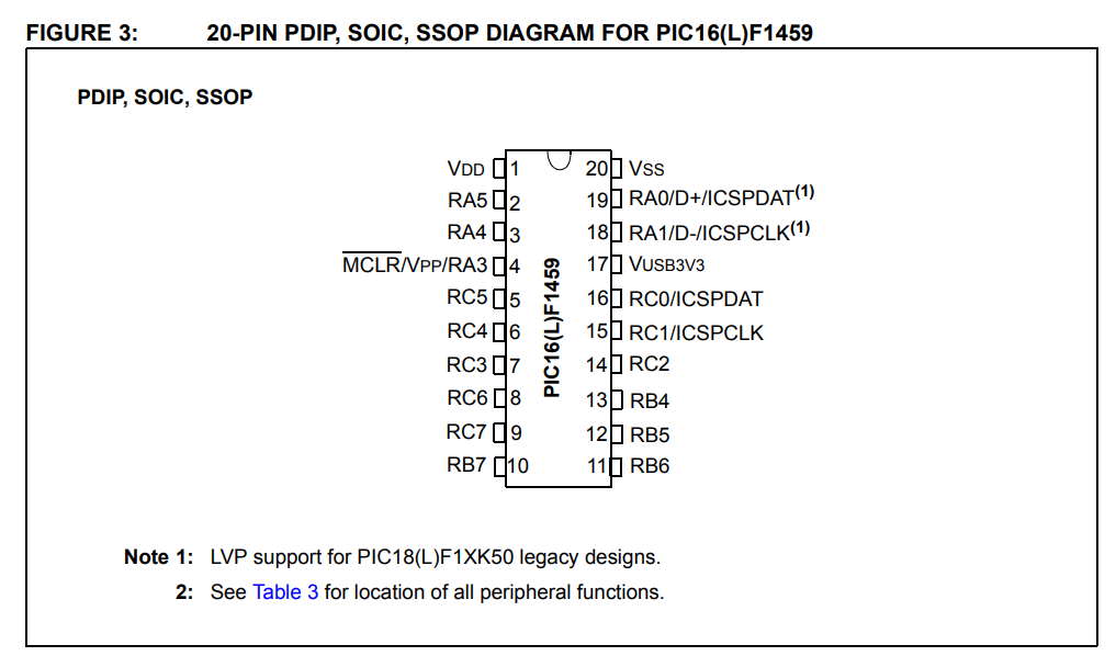
Now let's consider the parts used for the demonstration. First, the PIC itself - the PIC16LF1459:

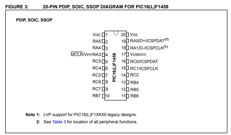
The PIC16LF1459 itself is a small, 8-bit microcontroller from Microchip with 14 KB of Flash memory per program, about 1 KB of RAM and a Full-Speed USB hardware controller. It operates at 2.0-3.6 V (the F version requires a higher voltage) and reaches up to 48 MHz (with PLL needed for USB), while offering several peripherals such as I²C, SPI, UART and ADC. Despite its very limited resources, the presence of a USB hardware module makes it suitable for experimental projects communicating directly with a computer. What's more, the whole thing requires a minimum of external components to operate - even an internal oscillator is sufficient, no 'quartz' is needed, and it comes in a hobbyist-friendly DIP enclosure.
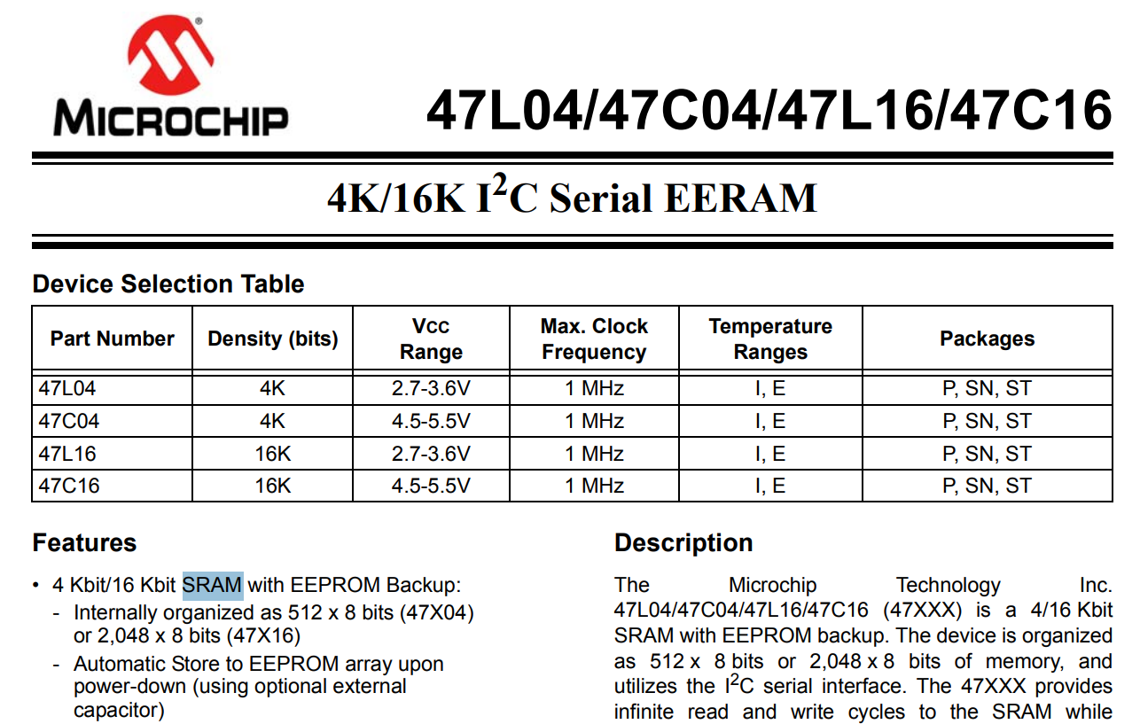
Now the EEPROM... or rather, sorry - EERAM, which is RAM with EEPROM support.

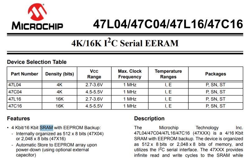
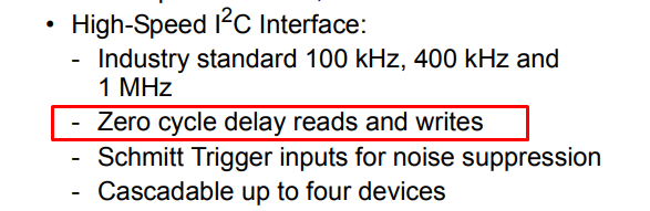
47L16, also in a DIP enclosure, with a staggering 16Kbit, or 2KB, size.

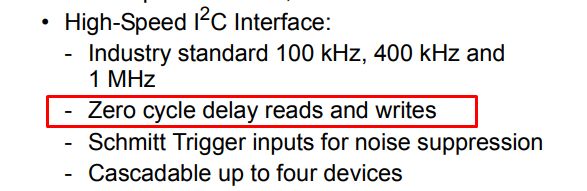
I chose this type of memory for a reason, and it's not just that I had it in the drawer. There is no latency when writing and reading with this bone - this may make the whole challenge a little easier for me and reduce waiting problems.


Memory boot
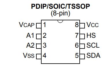
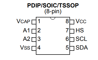
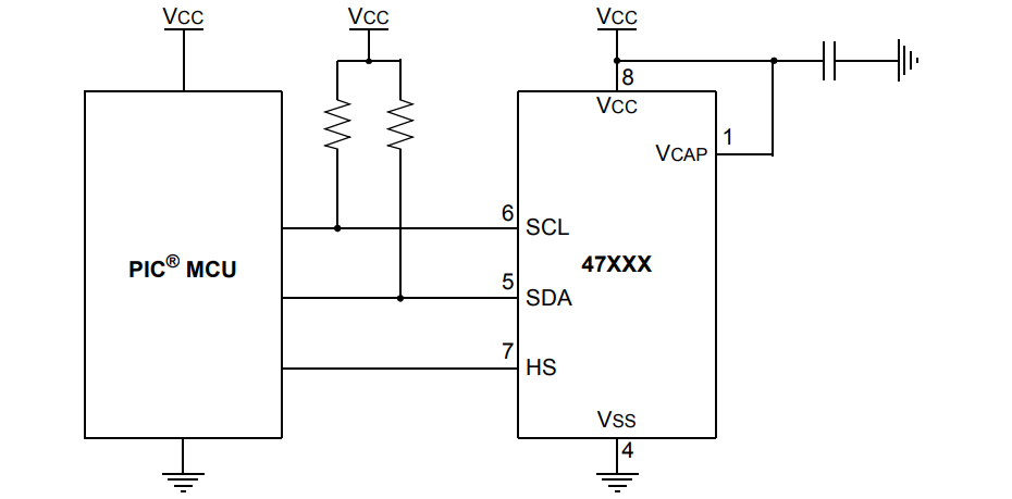
the 47L16 is connected to the PIC via the I2C bus. Two signals are needed, SDA (data) and SCL (clock), both with pull-up resistors for power supply.

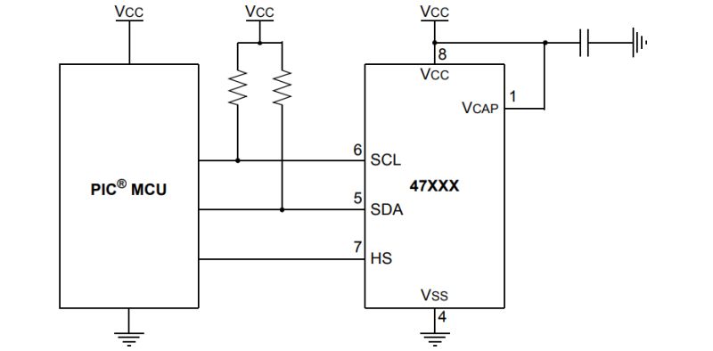
The HS pin forces a write (hardware store), but we can skip it here. I have connected it to ground. In addition, we have two more power pins, the mentioned ground and the address pins - these have internal pull down resistors, so I didn't even connect them.

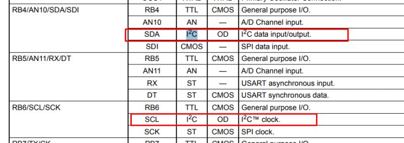
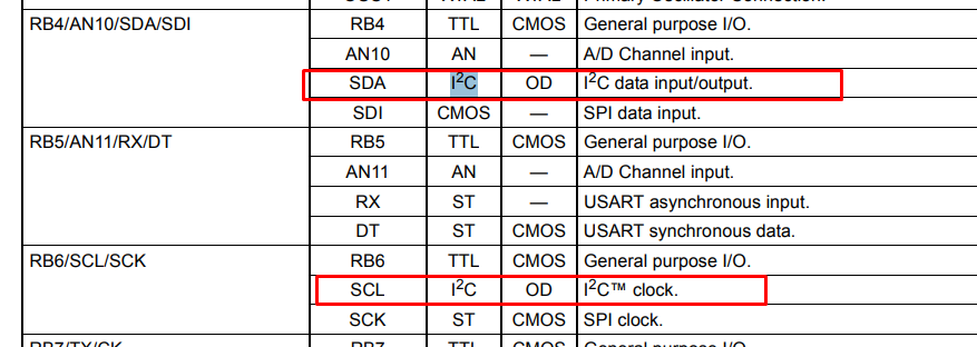
The PIC16LF1459 has hardware I2C, which is available on the hard-defined RB4 and RB6 pins. There is no PPS (Peripheral Pin Select) available on this PIC, allowing you to select any IO you like.

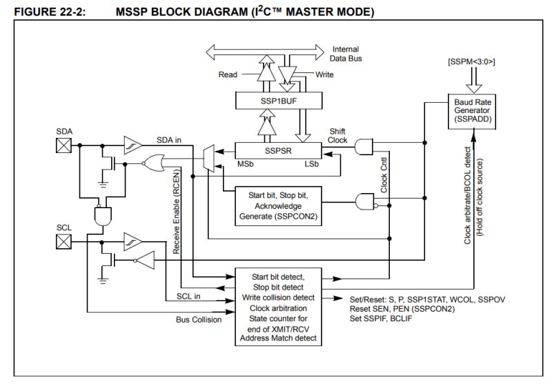
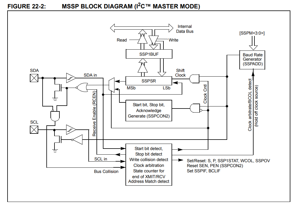
The PIC in question has hardware I2C, this means that we no longer have to manually swipe pin states using loops and delays in the program code. The microcontroller is equipped with a dedicated MSSP port system, which generates clock and data signals on the SDA and SCL lines independently and without our involvement. We only need to write a data byte into a special register (SSP1BUF) or issue a command by changing a single bit (e.g. SEN), and the rest of the work is taken over by the electronics. In this way, our task is virtually reduced to loading the data and waiting in a short loop until the hardware module signals that the sending is complete. Example implementation:
Code: C / C++
Log in, to see the code

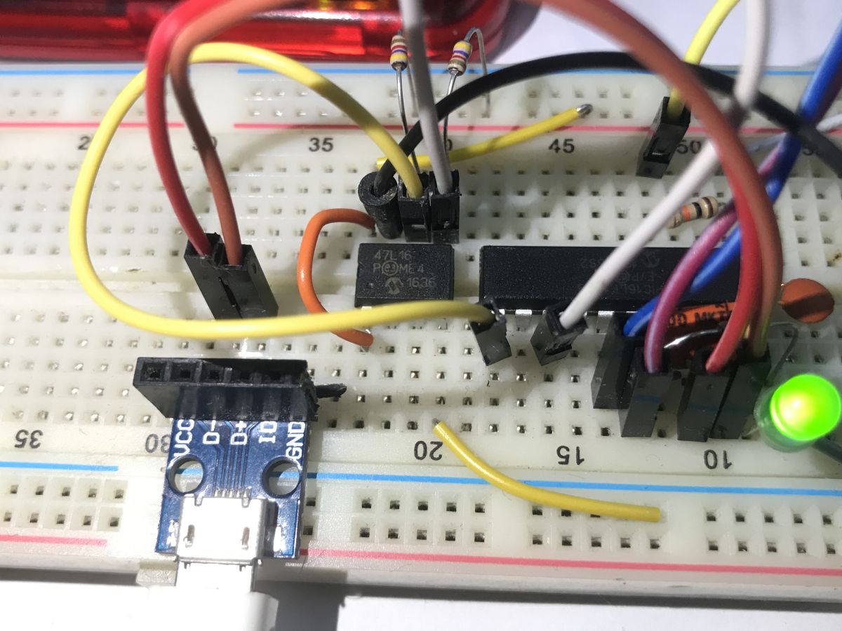
And this is what the completed connection looks like:

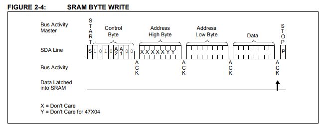
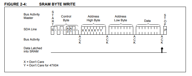
Now that we have I2C, we now need to do the communication with the memory - but this too is very simple, for example writing a byte is basically just establishing an I2C connection (after the memory address), specifying the address where we are writing (two bytes) and the destination data byte.

You just need to verify how this works - in my case it was implemented by a loop that wrote bytes sequentially and checked that the read returned what was written. If there were errors, I flashed the LED rapidly, and a correct read resulted in a slow flash.


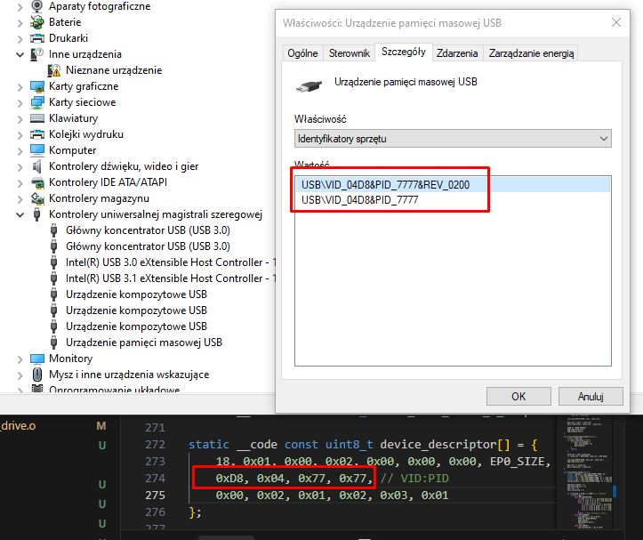
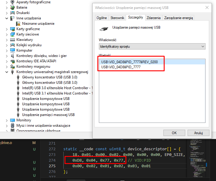
USB boot - part 1 - detection by device manager (USB descriptor)
Previous projects have relied on simple HID (Human Interface Device) classes - perfect for mice or keyboards. However, in order for the system to recognise our microcontroller as a portable memory device (flash drive) out of the box, we need to replace the USB descriptor with class 0x08, the Mass Storage Class, using the restrictive BOT (Bulk-Only Transport) protocol. This will allow the device manager to detect the storage medium, unfortunately it is still a long way from communicating with the file system.
Code: C / C++
Log in, to see the code


Using USB - Part 2 - Mass Storage Class
Unfortunately, Mass Storage Class operation is not as straightforward as with HID devices. Broadcasting simple packets of a few bytes is not enough. Storage support requires two new Bulk 'endpoints' (called Endpoints 1) to be reconfigured in the PIC - one to push data to the computer (IN) and one to receive it (OUT).
Code: C / C++
Log in, to see the code

Code: C / C++
Log in, to see the code

In addition to this, we need to start responding to the commands of the legendary SCSI standard, because it is in this archaic standard that Windows establishes a connection with us. SCSI (Small Computer System Interface) is a parallel data bus for transferring data between devices standardised back in the 1980s. USB Mass Storage still commands it today.

Using USB - Part 3 - SCSI commands
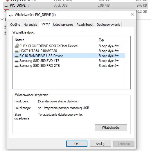
SCSI commands cover just the basic requests by which the system communicates with each medium. Our firmware has to play a specific role here: firstly, it presents itself as a disk and reports an artificial capacity (just 4 sectors of 512 bytes each). Secondly, it intercepts read and write requests for individual LBA numbers, redirecting data packets to the attached memory via I2C. The remaining supported items are merely diagnostic 'caps' that reassure the rigorous Windows driver and confirm the drive's continued operational readiness.
Code: C / C++
Log in, to see the code


Startup USB - part 4 - FAT file system
The final piece of the puzzle is to serve the operating system a comprehensible format - most simply the FAT family file system. Since we have declared only a few sectors in the capacity of the virtual disk, it is sufficient to deftly listen for requests hitting their numbers (LBA) and serve static arrays performing the task of Boot Sector, FAT area and Root Directory. In this simple way, we simulate disk logic on the fly, generating a 'file' in memory even without the use of external flash memory.
Code: C / C++
Log in, to see the code

This is an example of a rigidly created file/folder array for a root directory and a text document:
Code: C / C++
Log in, to see the code

The whole thing is prepared based on the FAT12 documentation available on the web. For those interested, I have included an explanation of each byte in the table:
Offset Size Description
00h 8 bytes Filename
08h 3 bytes Filename Extension
0Bh 1 bytes Attribute Byte
0Ch 1 bytes Reserved for Windows NT
0Dh 1 bytes Creation - Millisecond stamp (actual 100th of a second)
0Eh 2 bytes Creation Time
10h 2 bytes Creation Date
12h 2 bytes Last Access Date
14h 2 bytes Reserved for FAT32
16h 2 bytes Last Write Time
18h 18h 2 bytes
1Ah 2 bytes Starting cluster
1Ch 4 bytes File size in bytes

source: http://www.maverick-os.dk/FileSystemFormats/FAT12_FileSystem.html
Unlike a 'real' file system, here these arrays are fully static and 'pretend', and are not updated. You cannot, for example, create a file.


USB boot - part 5 - physical write to EERAM 47L16
That leaves the final piece of the puzzle, which, incidentally, I have already mentioned. Writing and reading from EERAM. This is plugged into LBA, which is the addressing of the logical blocks of the disk imposed on us by the SCSI protocol. When the system, in response to our artificial FAT array, sends a request to sector three (LBA 3), our program streams, byte by byte, the packets from the USB buffer straight into the bone over I2C and forces the data to be latched with a hard Software Store command. Such a trick significantly saves the microcontroller's already dramatically small RAM and, incidentally, makes the file immune in the event that the virtual pendrive is instantly unplugged from the socket.
The writing to the sectors itself is performed by bot_receive_chunk.
Code: C / C++
Log in, to see the code

Similarly, reading:
Code: C / C++
Log in, to see the code

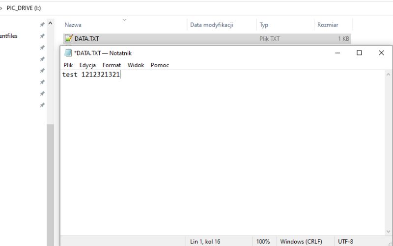
This is how writing and reading files works.


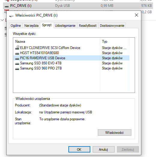
Tests and experiments
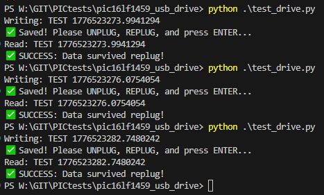
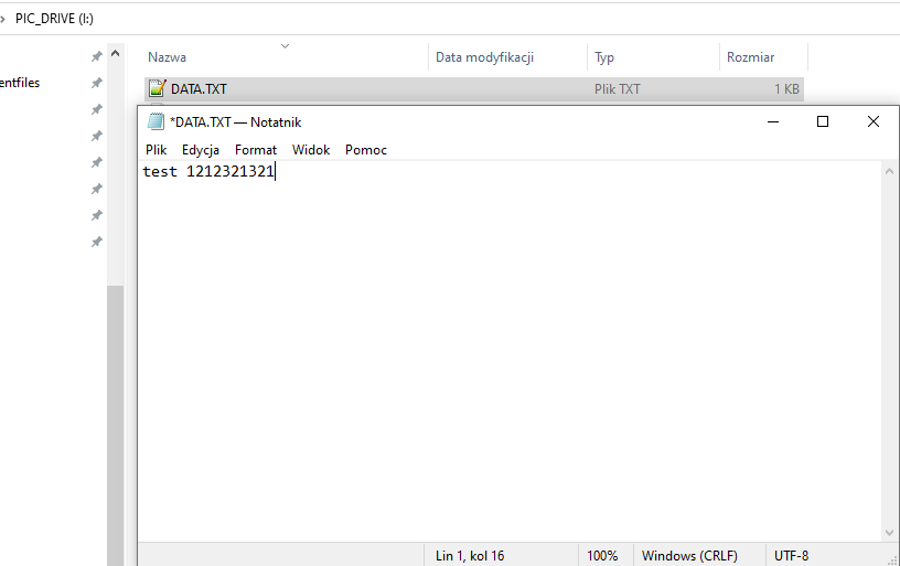
A flash drive prepared in this way is able to write a string of characters to a text file; moreover, the characters are able to survive a PIC reset and a complete power cut. On a side difficulty, I see that my Notepad++, after reading the file, sees additional NULL characters (null bytes) after the typed phrase, but I haven't diagnosed this - it probably doesn't respect the length of the file.

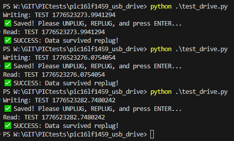
In addition, I have prepared a simple Python script to facilitate testing. I deliberately use r+ read operations there to avoid problems with the system trying to write to the next cluster....
Code: Python
Log in, to see the code


Summary
In summary, creating your own pen drive substitute on an 8-bit PIC boils down to simulating a functional storage medium complete with a mock-up file system and sector access. In the case shown here, such simulation is limited to feeding rigidly prepared, residual FAT12 headers and arrays, crafted to pretend to be a storage medium with a single file on a well-defined sector. Reads and writes from this sector are intercepted and redirected to the EERAM, which is fortunately fast enough to write and read without interfering with the PIC's communications.
One could go a step further here, and do it as it should be - the flash drive would then not know of the existence of FAT12, it would just share sectors, and Windows could format it at will. Worse, there's no room for that here - you'd have to try with more memory, maybe Flash? That's perhaps in the next section.
Is there any practical aspect to the current form of the project? There was no purpose in principle, but it could be argued that on a slightly larger PIC such a mechanism would be suitable for updating the batch or just communicating with the device. I have a few ideas for future projects, perhaps something can be realised soon.
Have you already run this type of memory carrier on a microcontroller?
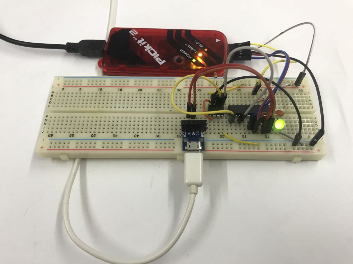
Attachments:
  • pic16lf1459_usb_drive_EERAM.zip (152.43 KB) You must be logged in to download this attachment.

About Author
p.kaczmarek2
p.kaczmarek2 wrote 14355 posts with rating 12263 , helped 649 times. Been with us since 2014 year.

Comments

Damian_Max 19 Apr 2026 22:19

The only 'use' (if you can say that at all xD), I can see, is to hold a read-only disk/database key on such a controller, a kind of dongle substitute/attraction. Cool experiment, I'm constantly surprised... [Read more]

p.kaczmarek2 20 Apr 2026 00:19

I don't know if it's a surprise.... I've been pestering USB for a good 10 years, this topic is still from 2016, that's what I started on: Pinguino4550 - USB development board for PIC18F4550 PIC16F1459... [Read more]

mamakapcia 20 Apr 2026 04:52

A very convenient solution if you want to make idiot-proof configuration access for the user running on multiple platforms. Of course, the question is whether such a basic file system will also take off... [Read more]

p.kaczmarek2 20 Apr 2026 07:53

I'll give it a try and let you know. The coolest thing is that you can conditionally do things from the USB (I didn't write about it in the first post, but then I tested it), so you can invoke storage... [Read more]

FAQ

TL;DR: With 14 KB Flash and 1 KB RAM, this PIC16LF1459 project proves that “art for art’s sake” USB storage is possible: it exposes a tiny 4-sector FAT12 disk, handles MSC/BOT/SCSI manually, and stores one text file in a 47L16 2 KB EERAM over I2C. It helps embedded developers learn how a USB flash drive works without external libraries. [#21886504]

Why it matters: This thread shows the minimum moving parts needed to make Windows see a bare microcontroller as a usable USB mass-storage device.

Option Capacity used here Write behavior Role in project
47L16 EERAM 16 Kbit / 2 KB No write latency during SRAM access; explicit store to EEPROM Persistent file data
Standard EEPROM Not used Slower write cycle would complicate USB timing Rejected for this demo
Larger Flash-based design Not built here Better fit for fuller disk emulation Suggested next step

Key insight: The hard part is not I2C storage. The hard part is making Windows accept the device by serving the right USB Mass Storage, BOT, SCSI, LBA, and FAT12 behaviors from a chip with only 1 KB RAM.

Quick Facts

  • PIC16LF1459 runs at 2.0–3.6 V, reaches 48 MHz with PLL for USB, includes Full-Speed USB hardware, and offers 14 KB Flash plus about 1 KB RAM. [#21886504]
  • The Microchip 47L16 EERAM provides 16 Kbit / 2 KB and was chosen because reads and writes have no normal EEPROM-style latency during SRAM access. [#21886504]
  • The emulated USB disk reports only 4 sectors × 512 bytes = 2048 bytes, matching the tiny memory target and simplifying FAT12 layout. [#21886504]
  • The USB interface descriptor uses Class 0x08, Subclass 0x06, and Protocol 0x50, which is the Mass Storage Class with SCSI over Bulk-Only Transport. [#21886504]
  • After writing sector data, the firmware issues a Software Store command and waits up to 25 ms so the EERAM copies SRAM contents into EEPROM-backed nonvolatile storage. [#21886504]

How do you build a USB mass-storage device from scratch on a PIC16LF1459 without using external libraries?

You build it by implementing every layer manually in C: USB descriptors, Bulk endpoints, BOT state handling, basic SCSI commands, a tiny FAT12 layout, and I2C storage access. On this PIC16LF1459, the firmware exposes a 4-sector disk, serves static sectors for boot/FAT/root data, and maps the writable file sector to a 47L16 over I2C. That works within 14 KB Flash and about 1 KB RAM, but only for a very small, tightly controlled disk image. [#21886504]

What is EERAM, and how is the Microchip 47L16 different from a regular EEPROM in this kind of pendrive project?

“EERAM” is nonvolatile RAM that behaves like SRAM during normal access, with a backup mechanism that copies contents into EEPROM for retention. In this project, the 47L16 differs from a regular EEPROM because the thread uses its near-instant read/write behavior during USB transfers, then explicitly stores data for power-loss survival. The device size here is 16 Kbit, or 2 KB, which exactly suits the tiny 4-sector demo drive. [#21886504]

Why was the 47L16 EERAM chosen instead of standard EEPROM or Flash for a PIC-based USB drive?

The 47L16 was chosen because it avoids normal EEPROM write latency while the PIC streams USB data over I2C. That makes the timing easier on an 8-bit controller with only 1 KB RAM, since the code can forward bytes directly instead of buffering large writes. The author also wanted persistence after unplugging, so the firmware forces a Software Store after the last sector write. Standard EEPROM would add waiting problems, and a fuller Flash design was left for a future project. [#21886504]

What does the USB descriptor need to look like for Windows to detect a PIC16LF1459 as a Mass Storage Class device?

It must identify the interface as USB Mass Storage with BOT and SCSI. In the thread, the configuration uses interface Class 0x08, Subclass 0x06, and Protocol 0x50, plus two Bulk endpoints: one IN and one OUT on Endpoint 1. That descriptor is enough for Windows Device Manager to recognize the PIC16LF1459 as a storage-class device, even before full file-system communication works. [#21886504]

How do Bulk-Only Transport and SCSI commands work in a custom USB flash drive implementation on a microcontroller?

Bulk-Only Transport wraps storage commands into USB Bulk transfers, and SCSI carries the actual read, write, inquiry, and capacity requests. This firmware receives a 31-byte CBW on EP1 OUT, validates the 0x43425355 signature, processes the SCSI command, moves data on EP1 IN or OUT, and finishes with a CSW. Windows still speaks this old SCSI command model to USB flash drives, so the PIC must emulate enough of it to look like a real disk. [#21886504]

What is LBA in USB mass storage, and how does it map to sectors when emulating a tiny FAT12 disk?

LBA is the logical block address, which numbers disk sectors starting from 0. In this design, LBA 0 serves the boot sector, LBA 1 serves the FAT area, LBA 2 serves the root directory, and LBA 3 maps to the real data sector stored in the 47L16. Each sector is 512 bytes, so the whole fake FAT12 disk is only 2048 bytes. [#21886504]

How can you implement I2C on the PIC16LF1459 using the MSSP hardware module to talk to a 47L16 EERAM?

Use the PIC16LF1459 MSSP hardware so the peripheral, not software delay loops, generates SDA and SCL timing. The thread places hardware I2C on fixed pins RB4 and RB6, then uses register-level routines for start, stop, byte write, and byte read through SSP1BUF, SSP1CON2, and SSP1STAT. 1. Wait until the bus is idle. 2. Issue start and send device plus address bytes. 3. Read or write payload bytes, then stop. [#21886504]

Why does a custom FAT12 text file on this PIC pendrive show extra NULL characters in Notepad++ after the written message?

The extra NULL characters appear because the emulated file content occupies a fixed 512-byte sector, while the editor reads beyond the typed text and sees padding bytes. The thread notes that Notepad++ shows trailing nulls after the message and suggests the editor may not be respecting the file length used by this minimal implementation. This is a side effect of the rigid, fake FAT12 layout rather than a full filesystem update path. [#21886504]

How do you create a minimal FAT12 boot sector, FAT area, and root directory for a fake 4-sector USB disk?

Create static byte arrays for the sectors Windows expects and return them by LBA. This firmware serves a boot sector with the 0x55AA signature at offsets 510 and 511, a FAT sector, and a root directory sector containing a volume label plus DATA.TXT. The directory entry points the file to cluster 2 and gives it a size of 512 bytes. The code never updates these structures dynamically, so the disk image stays fixed. [#21886504]

What are the practical limits of making a pendrive on a PIC16LF1459 with only 14 KB Flash and 1 KB RAM?

The main limits are tiny capacity, minimal filesystem behavior, and almost no buffering margin. This design exposes only 2 KB total disk space, supports one tightly defined writable area, and cannot behave like a general-purpose flash drive that Windows can freely format. The author states there is no room here for a fuller sector-sharing design, and a larger MCU or more memory would be needed for practical use. [#21886504]

Which SCSI commands are the minimum needed for Windows to accept a homemade USB storage device on a PIC?

This implementation uses a small set of SCSI commands that cover identity, size reporting, and block I/O. The code shown handles INQUIRY, READ CAPACITY (10), READ FORMAT CAPACITIES, READ (10), and WRITE (10), which is enough for the presented Windows interaction. The author describes the remaining responses as diagnostic “caps” that reassure the Windows driver that the medium is present and ready. [#21886504]

What is the Software Store command on the 47L16, and why is it needed after writing USB data over I2C?

The Software Store command tells the 47L16 to copy its SRAM contents into EEPROM-backed nonvolatile storage. In the thread, the firmware sends control address 0x30, command register 0x55, then command 0x33, and waits 25 ms because auto-store can take that long. That step matters because it makes the written text survive an immediate PIC reset or full power removal after the USB write completes. [#21886504]

How can you test a homemade PIC USB drive safely in Python without triggering writes to another cluster?

Use in-place overwrite mode and keep the write size fixed to one sector. The thread’s Python test opens I:\DATA.TXT with "r+", writes a 512-character padded string, asks for unplug and replug, then reads the file back and checks whether the new text survived. The author explicitly chose "r+" to avoid the OS extending the file into another cluster, which this minimal disk image does not support. [#21886504]

PIC16LF1459 versus a larger MCU with more RAM or native USB stack support: which is better for a custom mass-storage project?

A larger MCU is better for a practical mass-storage project, while the PIC16LF1459 is better for learning the protocol stack from first principles. This PIC can prove that manual MSC emulation works with 14 KB Flash and 1 KB RAM, but the author says a proper sector-sharing design or host-side formatting would need more memory, perhaps with Flash. “There’s no room for that here” is the thread’s clearest design verdict. [#21886504]

What microcontrollers or setups have people used to run this kind of custom memory carrier or USB flash-drive emulation project?

This thread documents one confirmed setup: a PIC16LF1459 with a 47L16 EERAM on I2C and a handcrafted USB MSC stack in C. It does not list other tested boards, chips, or community builds. The only broader guidance given is directional: try a larger PIC or another MCU with more memory if you want a less rigid disk, fuller formatting support, or a more practical USB storage implementation. [#21886504]
Generated by the language model.
%}