
logo elektroda
logo elektroda
X
logo elektroda

PIC12F683 - two-channel dimmer and encoder support on 128 bytes of RAM

p.kaczmarek2 1317 5

TL;DR

  • A PIC12F683 project builds a two-channel LED dimmer with a rotary encoder and pushbutton, despite only 128 bytes of RAM and one hardware PWM output.
  • Software PWM runs in GPIO code, the encoder uses a state machine to filter bad transitions, and the button toggles which dimmer channel is active.
  • Timer0 interrupts drive the dimming loop at about 50 kHz, and DIMMER_MAX was reduced to 50 to raise the output frequency.
  • The controller stores the last brightness in internal EEPROM, so settings survive power loss instead of resetting to default.
  • An AOD454 MOSFET drove LED strips directly from 5 V GPIO and stayed acceptable thermally, reaching 65 °C at 5.1 A.
Generated by the language model.
ADVERTISEMENT
Treść została przetłumaczona polish » english Zobacz oryginalną wersję tematu
📢 Listen (AI):
  • PIC12F683 - two-channel dimmer and encoder support on 128 bytes of RAM
    Here is an account of building a two-channel dimmer based on an 8-bit PIC12F683 microcontroller and parts from electrical junk. The project will be written in C using the SDCC compiler. A single encoder will be used to control the brightness levels, and pressing the encoder will toggle the bar being controlled at the time. The PWM will be realised programmatically on a timer and interrupt, as the PIC presented here has only one hardware channel for pulse generation, and my assumptions require at least two strips to be controlled.

    This topic is part of my series on PIC microcontrollers and the SDCC compiler. For other parts, please see the topics below:
    Part 1 - Setting up the operating environment
    https://www.elektroda.pl/rtvforum/topic3635522.html#18304424
    Part 2 - Blink LED, IO pins, digital inputs and outputs
    https://www.elektroda.pl/rtvforum/topic3647884.html#18389188
    Part 3 - Oscillator settings. Internal oscillator, external oscillator, quartz resonator, PLL
    https://www.elektroda.pl/rtvforum/topic3657704.html
    Part 4 - Timers, interrupts
    https://www.elektroda.pl/rtvforum/topic3676645.html#18580858
    Part 5 - Seven-segment display operation
    https://www.elektroda.pl/rtvforum/topic3676650.html#18580877
    Part 6 - MM5450 LED display driver
    https://www.elektroda.pl/rtvforum/topic3845301.html
    Related topics about PIC12F:
    PIC12F683 and SDCC - tutorial - we create a simple dimmer (read catalogue notes)
    Christmas WS2812 animations on PIC12F683 - how many LEDs will 128 bytes of RAM handle?

    Introduction
    This is another project on a tiny eight-bit - this time based on an encoder. I've already shown a dimmer in the past, so this time I decided to add such variety. In addition, my previous presentation was based on a microC, where some of the mechanisms are ready, and today I am creating from 0 in SDCC. Maybe this will interest someone, but still a glimpse of the MCU used.
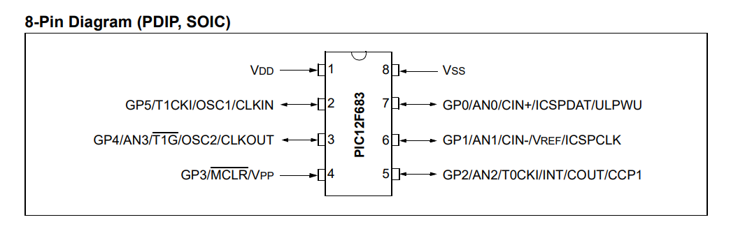
    PIC12F683 - two-channel dimmer and encoder support on 128 bytes of RAM
    PIC12F683 - two-channel dimmer and encoder support on 128 bytes of RAM
    2048 bytes of Flash for instructions and fixed data, 128 bytes of RAM for variables.... that's not a lot of memory, but it should be enough for a dimmer. The worse thing is that we only have one PWM, and I want to handle two strips:
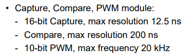
    PIC12F683 - two-channel dimmer and encoder support on 128 bytes of RAM
    I will undoubtedly implement the PWM programmatically, via GPIO operations.

    Part preparation
    I try to base my builds on parts from electrical junk, so I started with my collection of selected circuit boards:
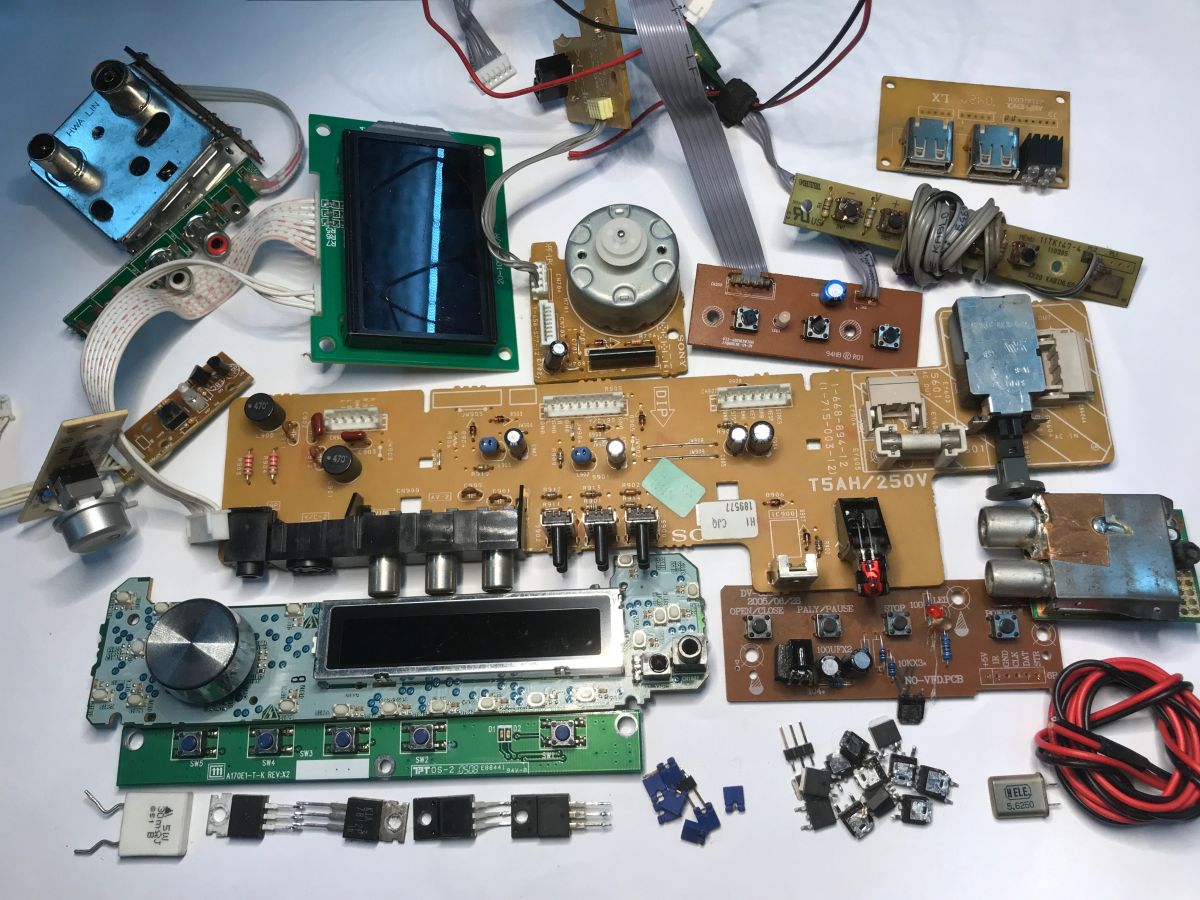
    PIC12F683 - two-channel dimmer and encoder support on 128 bytes of RAM
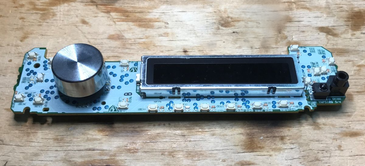
    A module from a car radio caught my eye. There is a display, a controller and encoder:
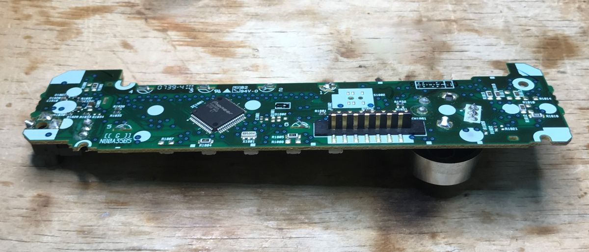
    PIC12F683 - two-channel dimmer and encoder support on 128 bytes of RAM PIC12F683 - two-channel dimmer and encoder support on 128 bytes of RAM
    The controller is a PD6340A. I could not find its datasheet online, although I did find a diagram of the radio. It is connected to the main controller by some strange two-pin protocol.
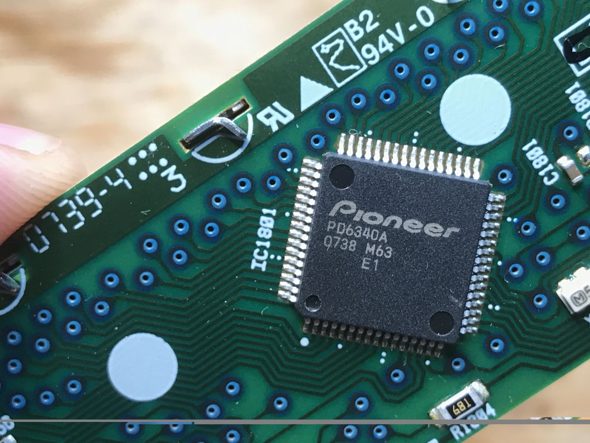
    PIC12F683 - two-channel dimmer and encoder support on 128 bytes of RAM
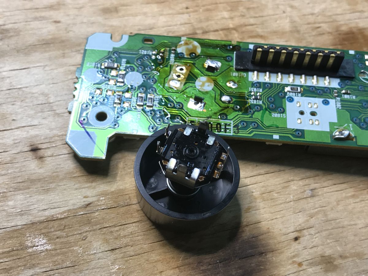
    I soldered the encoder using flux and braid - I apply flux to the solder, then press the braid to the solder with a hot tip. The braid collects the solder from the pads. Then I pull the component out, still helping myself with the soldering iron, as not all the binder will always collect.
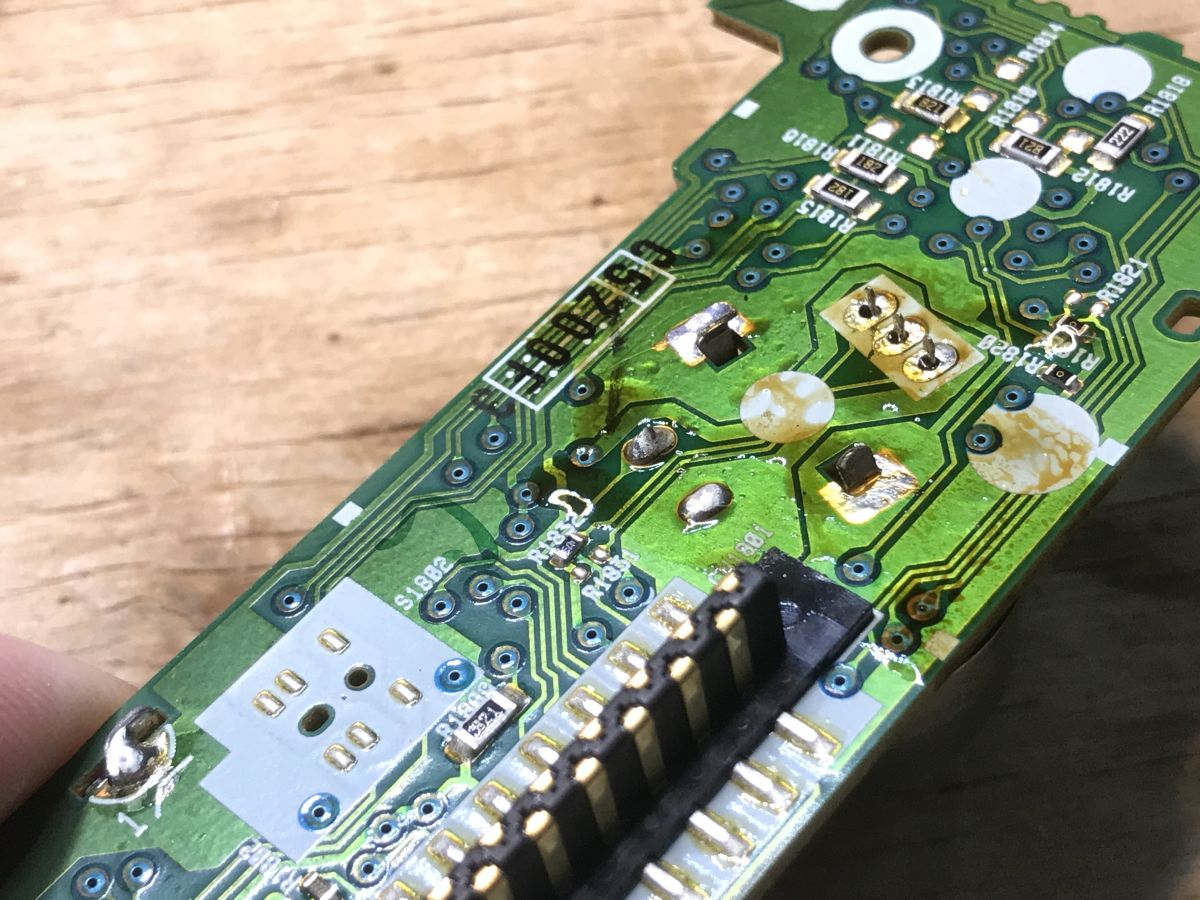
    PIC12F683 - two-channel dimmer and encoder support on 128 bytes of RAM PIC12F683 - two-channel dimmer and encoder support on 128 bytes of RAM
    I then specified the encoder leads.
    Here we have:
    - the encoder proper - that is, the "infinite potentiometer", whose outputs are three pins - ground and two signals, these three legs. I have whittled them down and added wires:
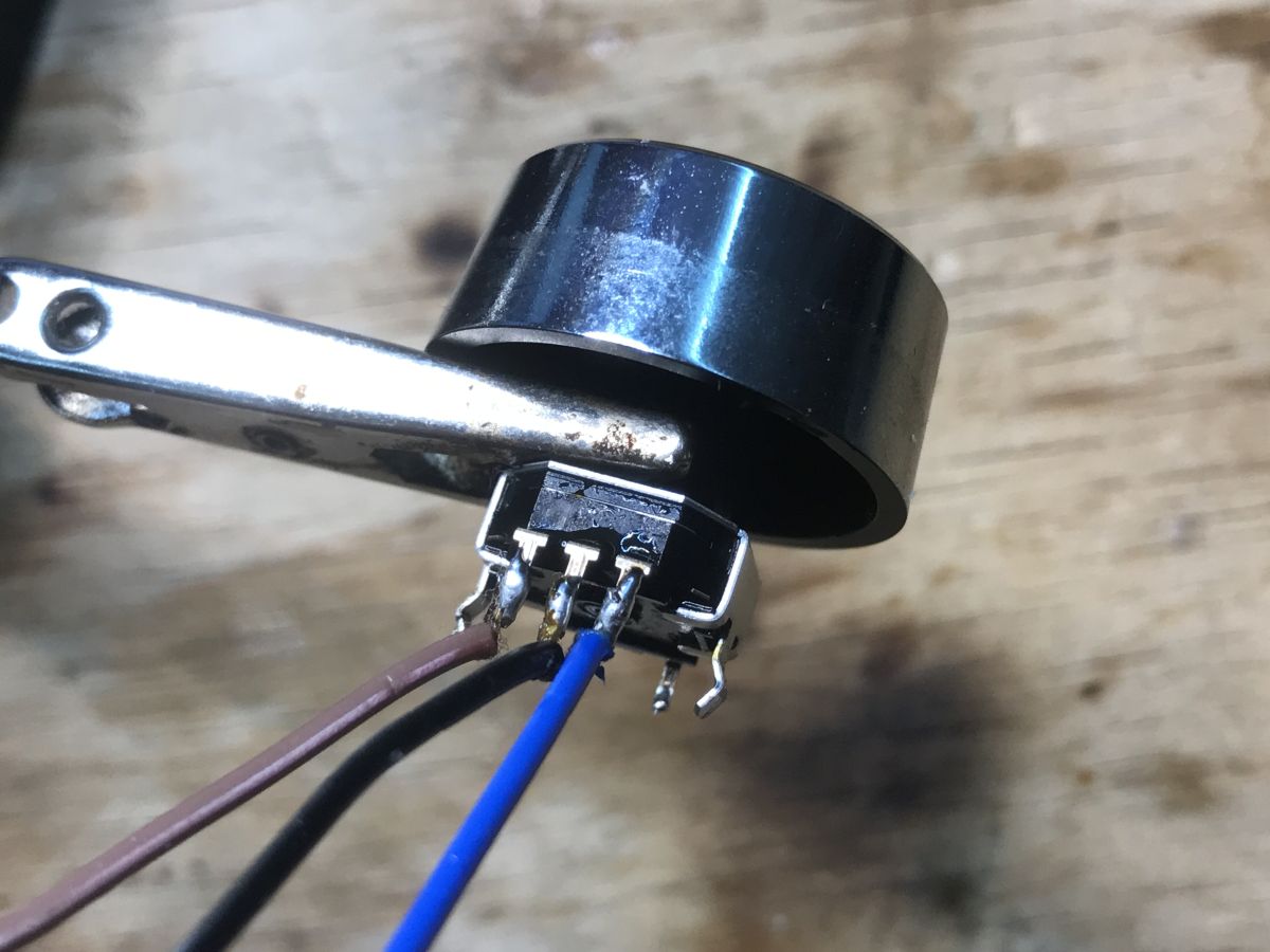
    PIC12F683 - two-channel dimmer and encoder support on 128 bytes of RAM
    - an extra button - simply pressing the encoder short circuits the circuit
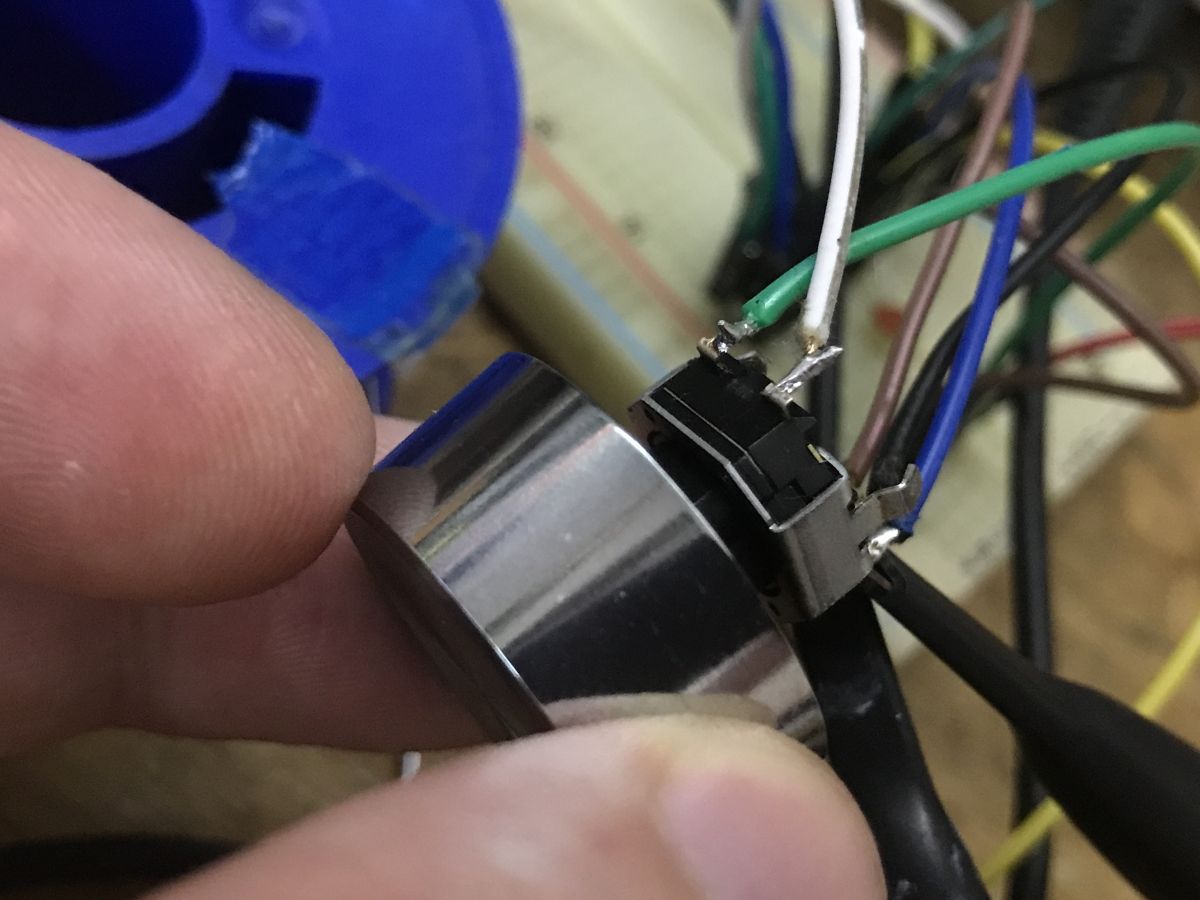
    PIC12F683 - two-channel dimmer and encoder support on 128 bytes of RAM

    Effect of encoder on oscilloscope
    I pulled up both outputs (extreme legs) of the encoder to the power supply via 10 kΩ resistors. I connected the middle leg to ground. I connected the oscilloscope probes to the outputs. Let's observe what happens on them.
    Turning clockwise:
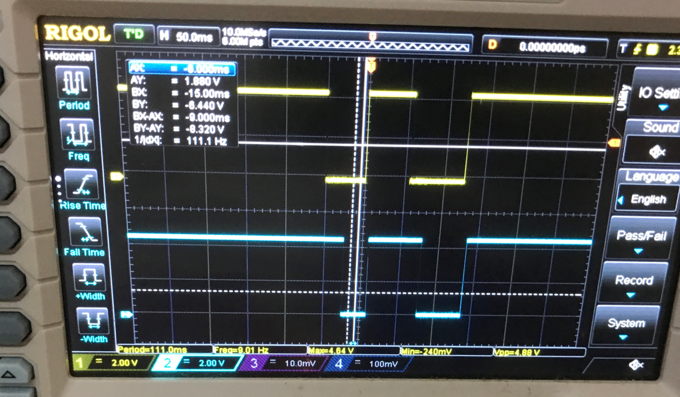
    PIC12F683 - two-channel dimmer and encoder support on 128 bytes of RAM
    The low state first appears on channel one (yellow waveform).
    Turning left:
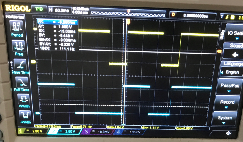
    PIC12F683 - two-channel dimmer and encoder support on 128 bytes of RAM
    The low state first appears on channel two (blue waveform).
    If there is no movement, we still have a high state on both outputs.
    We already have a stopping point - it still needs to be detected. Let's assume that we sample fast enough. When there is no movement, both digital pins will return 11, but when movement starts we get 10 or 01, depending on which way the encoder is turned.
    So many more of these states - as we have 2 pins (2 bits), we have 2^2 = 4 possible states. Additionally, we want to examine the state before and after, so we have two snapshots of 2 bits each, for a total of 2^3 = 8 possibilities.
    We decompose according to the oscilloscope transitions for the movement (let's assume) to the right:
    - 0b00 -> 0b01
    - 0b01 -> 0b11
    - 0b11 -> 0b10
    - 0b10 -> 0b00
    Any other transition means movement in the opposite direction, except for no change.
    This can already be entered in the code...

    First steps with the encoder
    First we include the header of the PIC used and set its configuration - internal oscillator, no watchdog.
    Code: C / C++
    Log in, to see the code

    Then we boot the PIC, disable the anolog pins and comparators, initialise the pin mode (two inputs - TRISIO), set the internal oscillator (OSCCON), enable the built-in pull up resistors (OPTION_REG and WPU - to set the default high state on the encoder outputs) and initialise the variables with their initial values.
    Code: C / C++
    Log in, to see the code

    Now it's time for the actual encoder logic. Here I take advantage of the fact that the two pins are right next to each other in the GPIO register. I simply shift it by 4 to get to the fourth bit and then do a logic product with bit 0b11 to just get the two values. I then compare them as I described earlier. Finally, I determine whether there was a clockwise or counterclockwise movement and based on that at that point I just turn the dimmer on or off.
    Code: C / C++
    Log in, to see the code


    Dimmer base
    The encoder is working, the dimmer can already be realised. The best way would be to do it on a hardware PWM, but the PIC12F683 only has one such output, and I ultimately want two. For this reason, I made a simple software PWM. I count the executions of the loop (from 0 to 100) and compare the current index with the dimmer value, which the encoder can also edit. In this way I get a smooth fill adjustment:
    Code: C / C++
    Log in, to see the code


    Fixes - higher frequency
    At this stage the first downside of software PWM came out. My DIMMER_MAX is too large - 100% fill requires too many steps. A hardware PWM would have been better, but there's only one such module here, so not enough for me. I implemented the most obvious fix, i.e. reducing DIMMER_MAX to 50, which had the effect of doubling the frequency of the generated signal.
    Code: C / C++
    Log in, to see the code


    Button and dimmer distribution
    Many encoders additionally have a button contained within them. This is the simplest microswitch, no major philosophy here. I have delegated one GPIO pin for it in input mode with a built-in pull-up resistor. This allows it to be forced into a default high state. Pressing the button shorts it to ground. When the button is pressed I flip the selected dimmer - now the program handles two separate dimmers. There is no support for contact oscillation (debouncing) in the code yet, but a small value capacitor such as 100 nF can be given between GPIO and ground.
    I describe the status of the dimmers with separate variables - I have not been tempted to make an array for now, although with more dimmers it would definitely be appropriate to use one.
    Code: C / C++
    Log in, to see the code

    I've tested the program and that's enough to operate two dimmers without contact vibration problems.

    Tests with LED
    Watching waveforms on an oscilloscope is one thing, but real tests with LEDs are no substitute. Maybe single LEDs will suffice for now. The PIC's GPIO can easily drive a regular LED:
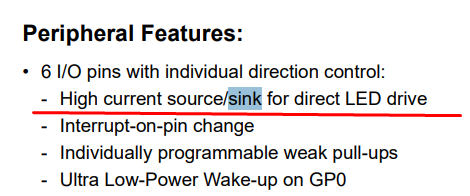
    PIC12F683 - two-channel dimmer and encoder support on 128 bytes of RAM


    Stability correction needed
    Brief tests with single LEDs, however, showed that practice is not as elegant as theory after all. Occasionally, fast rotation generated erroneous readings, making it somewhat difficult to set the highest or lowest brightness.
    Undoubtedly, there is a need to make this controller more secure and add tracking of the current and previous state.
    I decided to use the tried and tested solution from the Arduino. Still without interrupts, but more reliable:
    https://github.com/brianlow/Rotary/blob/master/Rotary.cpp
    Code: C / C++
    Log in, to see the code

    This method uses a state machine and examines whether the encoder has made a full movement one way or the other just according to these states. In the event of a wrong step, it appropriately 'rolls back' the state to the corresponding earlier step. Only specific final states indicate movement - here with the DIR_CW and DIR_CCW bytes attached.
    The implementation of the states here, in turn, boils down to holding their very indices in an array - for example, being in the R_START state we are in the first row of the array, now we have a reading from two GPIOs (4 possible values) and with these indices we specify a column from the first row, and the value from this column is the index of the new state (and possibly the DIR movement code).
    The array is chosen to handle all possible transitions between states, so it contains as many as 7*4=28 possibilities.
    It is worth looking, for example, at the second row - index R_CW_FINAL - there you can see that if something goes wrong, you do not get DIR_ information, but return to R_START.

    After these changes, I can no longer call up incorrect reads in any way.


    Flipping the dimmer to timer
    The second necessary fix is to move the dimmer operation to a hardware timer. Such a timer can run at a frequency we specify and call an interrupt where we handle the software PWM creation. I can't just use an off-the-shelf PWM here, because this PIC only has one hardware PWM (based on CCP1).
    What needs to be done to start Timer0 with an interrupt?
    First we set bit 5 (Timer 0 clock source) and bits 2-1 (prescaler) in OPTION_REG:
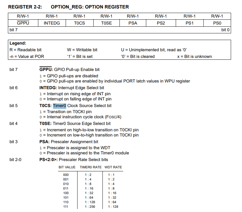
    PIC12F683 - two-channel dimmer and encoder support on 128 bytes of RAM
    We then enable general interrupts and Timer 0 overflow interrupts in INTCON:
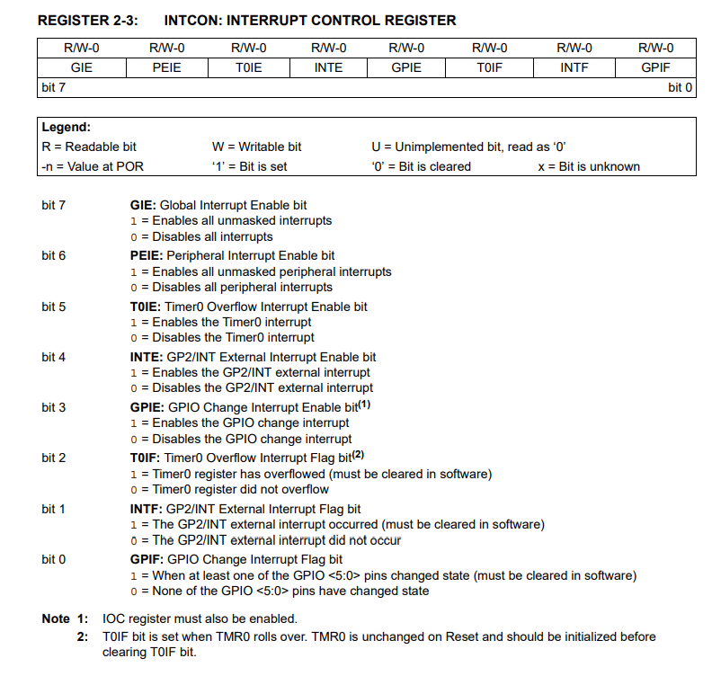
    PIC12F683 - two-channel dimmer and encoder support on 128 bytes of RAM
    You still need to set the value of TMR0, which is the one that will be counted down. The interrupt will be called when 0xFF - > 0x00 of this value is overflowed.
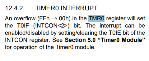
    PIC12F683 - two-channel dimmer and encoder support on 128 bytes of RAM
    Personally, I wanted a reasonably fast interrupt, so I selected a 1:1 prescaler, so since Timer0 goes at Fosc/4, TMR0 is incremented at 2 MHz. Now all we need to do is select the value of TMR0 so that our interrupt calls at about 50 kHz. This is because I have 50 degrees of brightness (DIMMER_MAX) and I want about 1 kHz at the output. I can always reduce DIMMER_MAX significantly if I need to and relieve the CPU.
    The last thing to remember is to reset TMR0 to the desired value in the interrupt and to clear the timer interrupt flag.
    All code:
    Code: C / C++
    Log in, to see the code


    Transistor selection
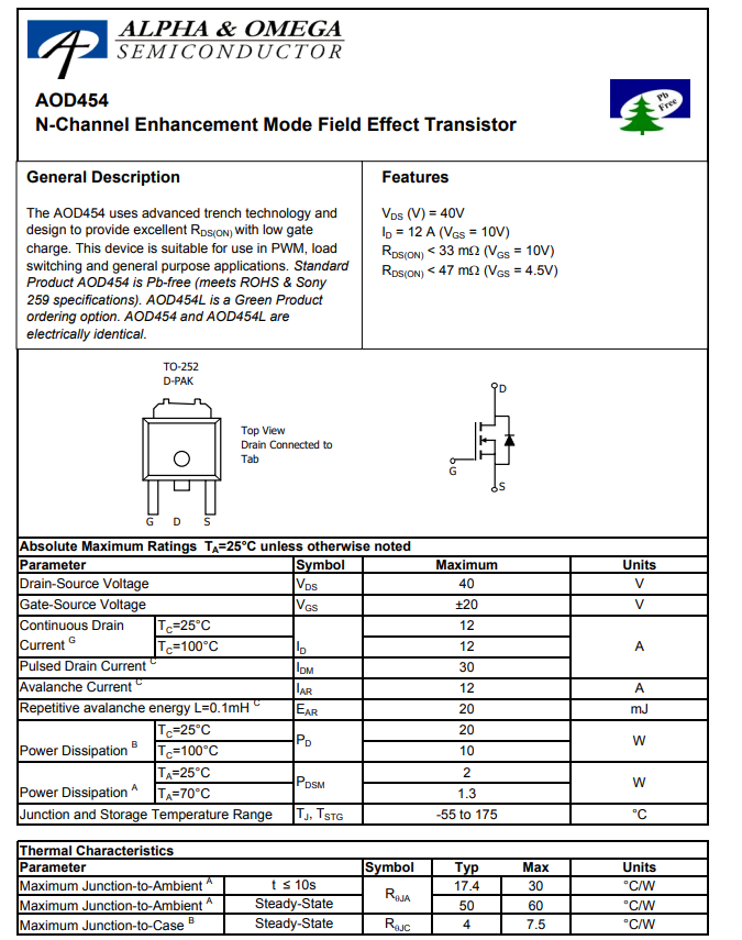
    Often when dismantling various electrical junk, I solder and put away transistors. Before soldering, I check their parameters to collect what I can use. One day a couple of D454s, actually AOD454s, ended up in the inverter from the monitor backlight.
    PIC12F683 - two-channel dimmer and encoder support on 128 bytes of RAM
    This is an N-type channel MOSFET with a fairly high drain current (12 A at Vgs=10) and low resistance in the open state. The PIC12F would control it directly from its pins (more precisely: via a resistor), so the gate voltage would be 5 V. The datasheet note shows that at Vgs=5 V, Rds(on) is 47 mΩ, which is an acceptable value. Not every transistor can be driven from such a low voltage. For the detailed behaviour of the transistor, refer to the graphs in the datasheet note.
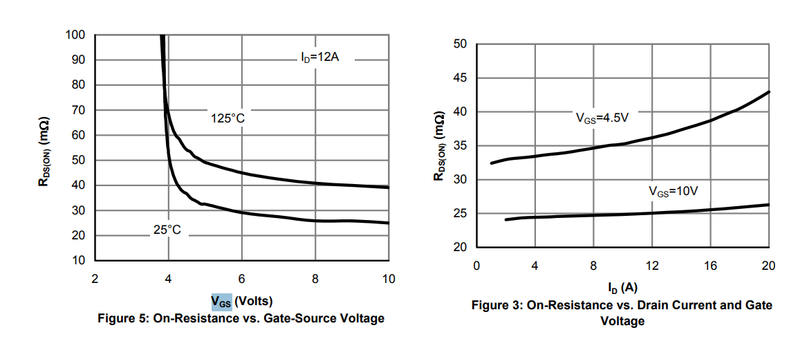
    PIC12F683 - two-channel dimmer and encoder support on 128 bytes of RAM
    This is, of course, a considerable simplification, but in such a simple case my choice worked.

    Tests with LED strip
    I wanted to check how much my transistor would heat up. Choosing a transistor along with a gate resistor is not a trivial matter and far beyond the subject of this short PIC presentation so I wasn't expecting sensational results, but I still had to see if it would work at all.
    The transistor was soldered onto a small piece of copper-coated laminate, so heat dissipation was quite reduced, but maybe that's better - you can always improve performance.
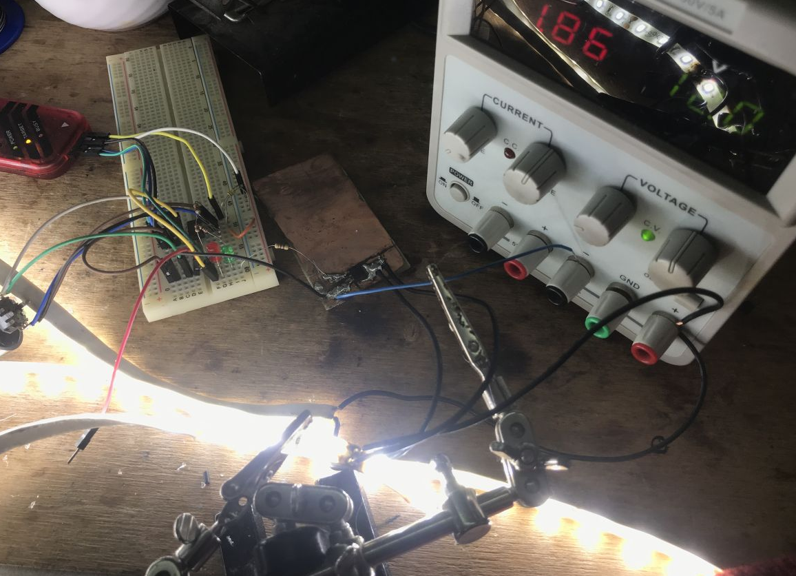
    I tested everything with a laboratory power supply at 12 volts, attaching more LED strips to increase the load.
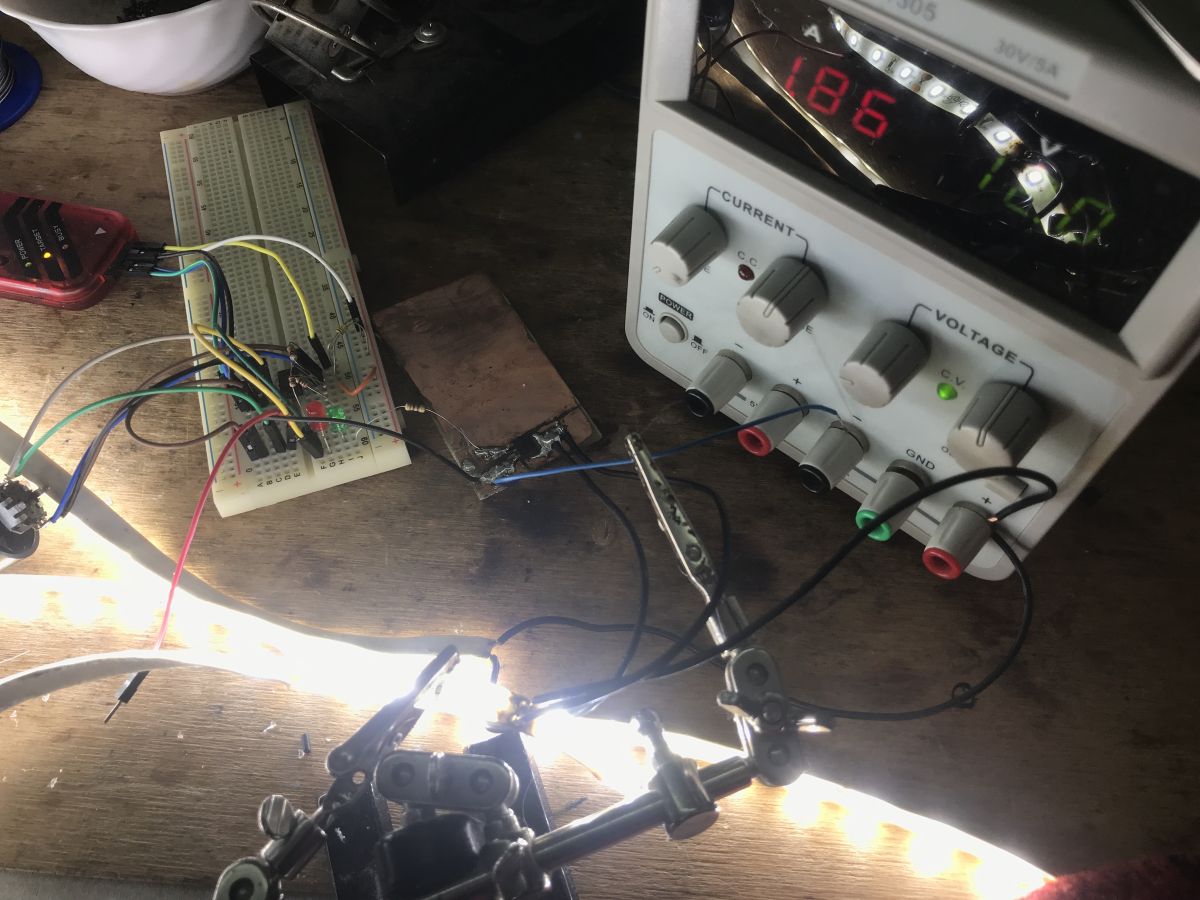
    PIC12F683 - two-channel dimmer and encoder support on 128 bytes of RAM
    By the way, I advise you against testing LED strips this way, even the rollers bend from the heat, the adhesive layer under the strip also degrades.
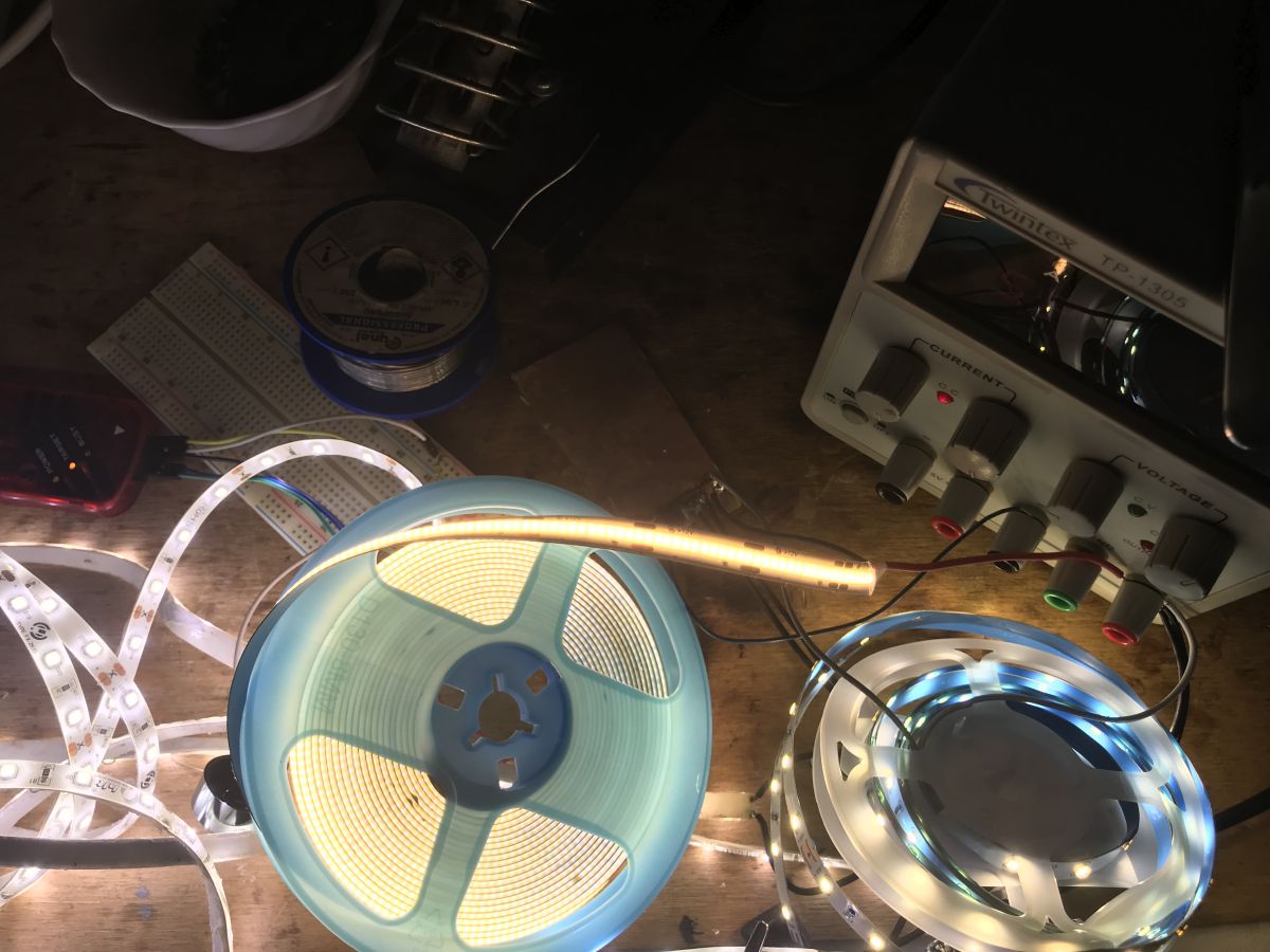
    PIC12F683 - two-channel dimmer and encoder support on 128 bytes of RAM
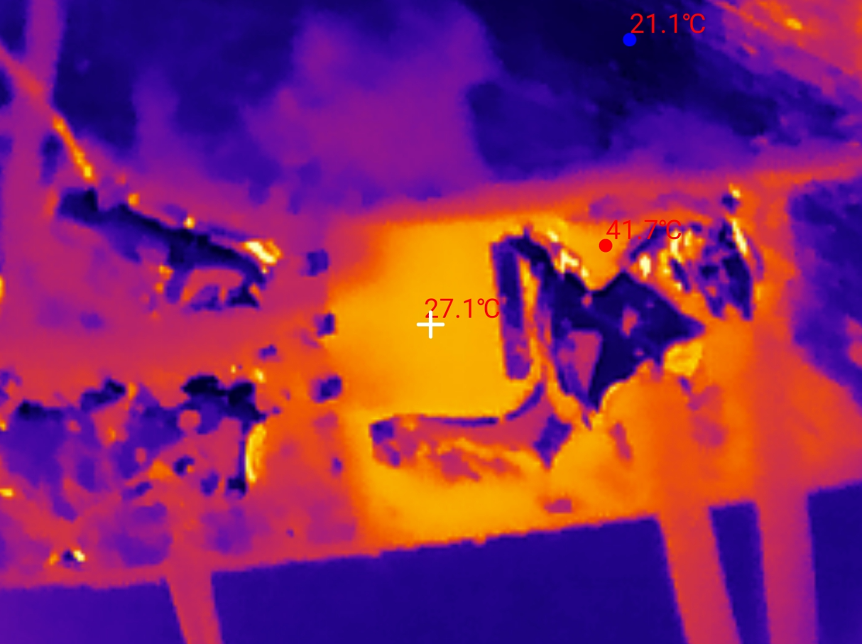
    At a load of 0.66 A, the transistor is cold. This 40 °C is only due to reflection in the binder.
    PIC12F683 - two-channel dimmer and encoder support on 128 bytes of RAM
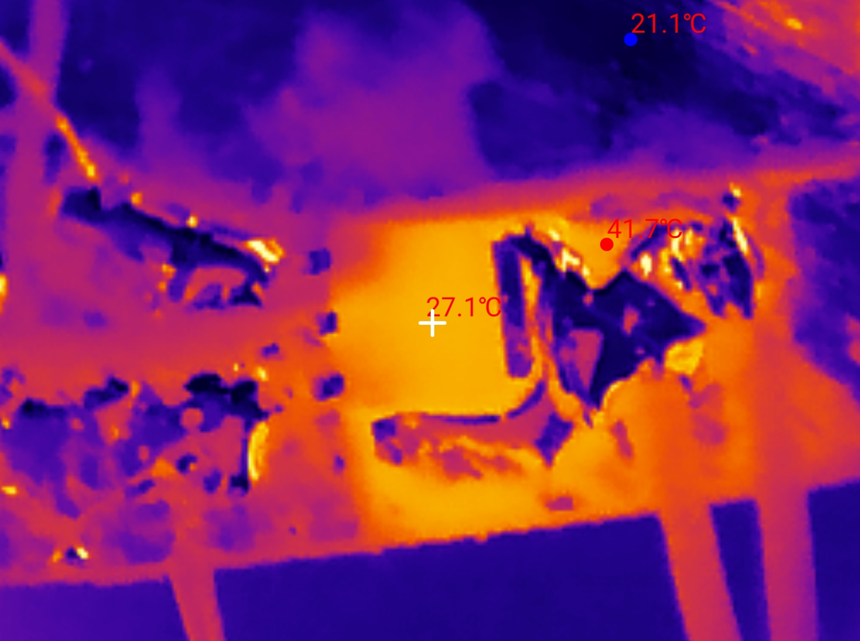
    At a load of 1.85 A the transistor only starts to heat up, it reaches just under 30 °C.
    PIC12F683 - two-channel dimmer and encoder support on 128 bytes of RAM
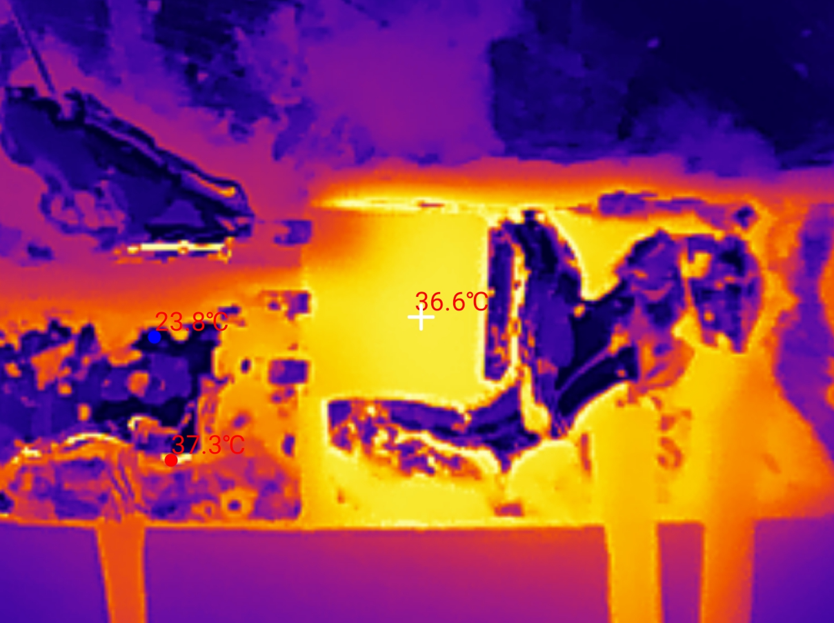
    At a load of 2.9 A, the transistor exceeds 35 °C.
    PIC12F683 - two-channel dimmer and encoder support on 128 bytes of RAM
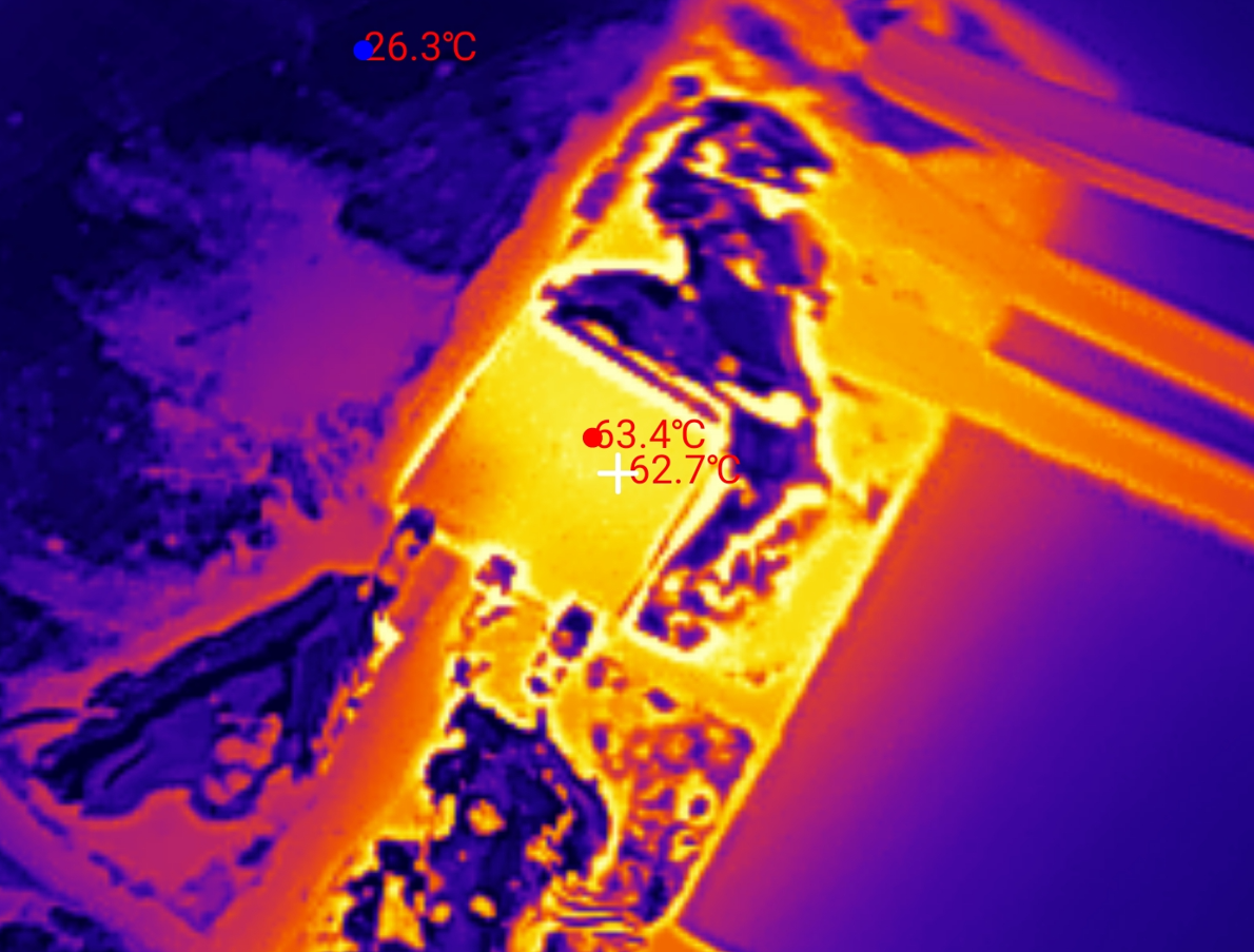
    At a load of 5.1 A, the transistor reaches 65 °C.
    PIC12F683 - two-channel dimmer and encoder support on 128 bytes of RAM
    Probably if only some heatsink were added, the temperature would drop even further.
    The results are fully satisfactory to me.


    Write to internal EEPROM
    One shortcoming remains. The dimmer now forgets its setting when it is powered off. Most of the time this is not a problem, as we tend to assume that the PIC is powered all the time, but some people may have occasional power outages and it is not desirable for the dimmer to forget its setting then.
    In the case of very short power outages, one could combine and give extra capacitors on the PIC's power line, but this is unlikely to make sense in the long run.
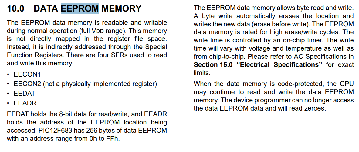
    Fortunately, our tiny PIC has a whole 256 bytes of non-volatile EEPROM:

    PIC12F683 - two-channel dimmer and encoder support on 128 bytes of RAM
    The embedded EEPROM is controlled by several registers with names starting with EE:
    PIC12F683 - two-channel dimmer and encoder support on 128 bytes of RAM
    EEDAT stores the data byte, EEADR its address. EECON1 controls memory operations.
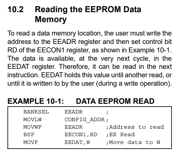
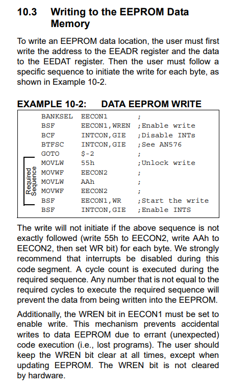
    Write and read operations are also described in the data note.
    PIC12F683 - two-channel dimmer and encoder support on 128 bytes of RAM PIC12F683 - two-channel dimmer and encoder support on 128 bytes of RAM
    Reading is the simplest - simply set the address, RD bit and then read the data.
    Writing is similar, but slightly more difficult - we enable the write, disable the interrupts, and then send the magic 0x55 0xAA values, and only then start the write and wait for it to succeed.
    I only need to do the read once after the MCU starts, I do the write with each change.
    Code: C / C++
    Log in, to see the code


    Optimising EEPROM consumption
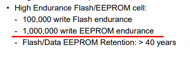
    Recording with each change is not an optimal approach. By rotating the encoder we will have a lot of these changes, after all, with 50 brightness levels here we have a good 50 records. This will wear out the EEPROM faster, although with its robustness, it can be solidly argued that it really does take a lot of such 'dimming' cycles to damage it:
    PIC12F683 - two-channel dimmer and encoder support on 128 bytes of RAM
    Nevertheless, I will give a simple way how this could be improved. You simply need to reduce the number of writes - you could, for example, save when the user finishes an operation. The question arises how to detect this - probably the easiest way is to reset the cycle counter to a given fixed value when the brightness level changes, and keep decreasing it in the background as long as it is not zero. When it reaches zero after decreasing, then we make a save.
    A similar procedure is useful (and perhaps more useful) when writing directly to Flash memory, which may have fewer predicted erase/write cycles.

    Summary
    This time the PIC12F683 was fully up to the task at hand, and it would probably even be possible to drive more LED strips this way - we are only limited by the amount of free GPIOs. With 8 pins, including ground and power, we are left with 6 candidates to use. Ostensibly there is the MCLR, but you can disable its RESET role and use it as GP3. GP3 can only be an input, but for a button it will do. So 6 pins, including 3 for the encoder - I'm unlikely to skip that. That leaves 3 pins for LED strips. It would be possible to make an RGB version. The selected transistor is also doing well. 65 °C at 5 A is rather good. One could now think of some 3D printed housing and we have a functional dimmer.

    Cool? Ranking DIY
    Helpful post? Buy me a coffee.

    About Author
    p.kaczmarek2
    Moderator Smart Home
    Offline 
    p.kaczmarek2 wrote 14506 posts with rating 12506, helped 651 times. Been with us since 2014 year.
  • ADVERTISEMENT
  • #2 21881705
    androot
    VIP Meritorious for electroda.pl
    Posts: 1801
    Help: 54
    Rate: 635
    Isn't it simpler to interrupt on the edge from one input and check the state of the other to distinguish the direction?
  • ADVERTISEMENT
  • #3 21881964
    Mateusz_konstruktor
    Level 37  
    Posts: 4173
    Help: 266
    Rate: 1101
    p.kaczmarek2 wrote:
    We could now think of some 3D printed housing and we have a functional dimmer.

    I am of a different opinion.
    How much will be the load on the output of the PIC in full brightness state?
    How much will the diode current be in the full brightness state?
  • ADVERTISEMENT
  • #4 21883134
    ZbeeGin
    Level 39  
    Posts: 4312
    Help: 602
    Rate: 449
    p.kaczmarek2 wrote:
    Now it's time for the actual encoder logic.

    I did it like this:
    Code: C / C++
    Log in, to see the code
  • ADVERTISEMENT
  • #6 21902602
    p.kaczmarek2
    Moderator Smart Home
    Posts: 14506
    Help: 651
    Rate: 12506
    @androot Good idea with the interruptions, I'll try to present it too.

    Mateusz_konstruktor wrote:

    How much will the diode current be in the full brightness state?

    What specifically are you getting at? Measuring quickly, one LED chain above the window at my place needs 1.5 A at the highest brightness. The one in the kitchen not much less, 1 A. These types of currents at my place are.


    @xangel familiar issue, e.g. in my open source firmware we have such an approach to flash saving that we divide the 4096 B sector into zones of 64 bytes each and write data to them, marking them accordingly (e.g. with a header or flag). Only when the entire page is full do we perform a new erase cycle and start writing from the beginning. This significantly reduces memory consumption, as it is the erase cycles that consume the most, not the writes themselves.
    https://github.com/openshwprojects/OpenBK7231T_App
    Helpful post? Buy me a coffee.
📢 Listen (AI):

FAQ

TL;DR: With 128 bytes of RAM and 2 PWM channels, this PIC12F683 dimmer proves that "only one hardware PWM" is not a blocker. It uses SDCC C, GPIO-based encoder decoding, Timer0-driven software PWM, and EEPROM save/restore. This FAQ helps hobbyists build a compact two-channel LED strip controller with one encoder and one push button. [#21881566]

Why it matters: This design shows how to turn a very small 8-bit MCU into a practical dual-channel LED dimmer without adding dedicated encoder or PWM hardware.

Approach Encoder handling PWM method Main advantage Main drawback
Simple GPIO polling Transition comparison Loop-based software PWM Easiest code Wrong reads at fast rotation
State-machine polling 7x4 state table Loop-based software PWM Reliable direction detection PWM frequency still limited
State-machine + Timer0 7x4 state table Interrupt-driven software PWM Stable two-channel dimming More setup complexity

Key insight: The winning combination is not a faster loop, but a better architecture: decode the encoder with a state machine and move PWM generation into a Timer0 interrupt. That fixes both missed turns and visible PWM limitations.

Quick Facts

  • PIC12F683 resources used in the project: 2048 bytes Flash, 128 bytes RAM, 1 hardware PWM, and 256 bytes EEPROM for saved brightness settings. [#21881566]
  • The encoder was wired with internal pull-ups on GP5, GP4, and the push button on GP2; outputs were placed on GP0 and GP1. [#21881566]
  • Final PWM setup used the 8 MHz internal oscillator, Timer0 prescaler 1:1, TMR0 = 128, and DIMMER_MAX = 50 to target about 1 kHz output with about 50 kHz interrupt activity. [#21881566]
  • Measured AOD454 MOSFET temperatures stayed modest in testing: about 30 °C at 1.85 A, above 35 °C at 2.9 A, and about 65 °C at 5.1 A on a small copper-clad board. [#21881566]

How do you build a two-channel LED strip dimmer on a PIC12F683 in C with the SDCC compiler when the chip has only 128 bytes of RAM?

Build it by keeping the architecture minimal: use one rotary encoder for input, store two brightness bytes, generate two PWM outputs in a Timer0 interrupt, and save settings in the internal EEPROM. The final design uses GP4 and GP5 for the encoder, GP2 for the button, GP0 and GP1 for LED control, and DIMMER_MAX = 50 to keep timing manageable on an 8 MHz PIC12F683 with 128 bytes of RAM. [#21881566]

What is a quadrature encoder, and how do the two output signals indicate clockwise and counterclockwise rotation?

A quadrature encoder is an electromechanical input device that outputs two digital signals in phase shift, letting a controller detect both movement and direction from the order of transitions. In this project, both lines rest at high, clockwise rotation makes channel 1 go low first, and counterclockwise rotation makes channel 2 go low first, which produces state sequences such as 00→01→11→10→00. [#21881566]

How can you decode a rotary encoder on PIC12F683 using GPIO polling and a state machine instead of dedicated encoder hardware?

Read GP4 and GP5 repeatedly, combine them into a 2-bit value, and feed that value into a state table. The project uses a 7-state by 4-input lookup table that returns either DIR_CW or DIR_CCW only after a valid full step. This approach needs no dedicated encoder peripheral, only two GPIO inputs, a state byte, and a small transition table. [#21881566]

Why did the simple encoder-reading method on the PIC12F683 produce wrong readings during fast rotation, and how does the Arduino-style state table fix it?

The simple method failed because fast rotation created skipped or ambiguous transitions that the direct previous/current comparison could misread. The 7x4 state table fixes that by accepting only valid step sequences and rolling invalid paths back to safe states. The author reported the result clearly: "After these changes, I can no longer call up incorrect reads in any way." [#21881566]

What's the difference between hardware PWM and software PWM on the PIC12F683, and which approach is better for controlling two LED channels?

Hardware PWM is built into the MCU and runs independently, while software PWM toggles GPIO pins in code using a counter and timing source. On the PIC12F683, hardware PWM is better for one channel because it is cleaner and cheaper in CPU time, but it is not enough here because the chip has only one PWM module. For two LED channels, Timer0-driven software PWM is the better fit. [#21881566]

How do you configure Timer0 interrupts on a PIC12F683 to generate software PWM for two dimmer outputs?

Configure Timer0 so it generates a fast periodic interrupt, then update both outputs inside the ISR. 1. Set the internal oscillator to 8 MHz and use Timer0 with prescaler 1:1. 2. Enable global interrupts and Timer0 overflow interrupts in INTCON. 3. Reload TMR0 to 128 in the ISR, increment pwm_counter, wrap at DIMMER_MAX = 50, and compare that counter with dimmer0 and dimmer1 to drive GP0 and GP1. [#21881566]

What is EEPROM in the PIC12F683, and how can it be used to remember dimmer brightness settings after a power loss?

EEPROM is non-volatile memory that keeps data after power is removed, unlike the PIC12F683's 128-byte RAM. This project stores dimmer0 at address 0 and dimmer1 at address 1, reads them once during startup, and restores default values if either read exceeds DIMMER_MAX = 50. Writing uses EEADR, EEDATA, WREN, the 0x55/0xAA unlock sequence, and WR completion wait. [#21881566]

How can you reduce EEPROM wear in a PIC12F683 dimmer project instead of writing the brightness value after every encoder step?

Delay the save until the user stops turning the encoder. The thread recommends resetting a countdown timer on every brightness change, decrementing it in the background, and writing to EEPROM only when it reaches zero. That reduces write bursts dramatically, because one full sweep across 50 brightness levels otherwise causes about 50 writes for a single adjustment. [#21881566]

What is the best way to wire a rotary encoder with push button to PIC12F683 GPIO pins using internal pull-up resistors?

Wire the encoder's common pin to ground, connect the two signal pins to GP4 and GP5, and enable internal pull-ups so both lines idle high. Wire the push button to GP2 with the same pull-up approach, so pressing the encoder shorts GP2 to ground. In the project, TRISIO is set to 0b00110100 and WPU to 0b00110100 for exactly that layout. [#21881566]

How do you debounce the encoder button on a PIC12F683 dimmer, and when is a 100 nF capacitor enough?

Use the internal pull-up and treat the button as active-low, then add a small capacitor only if bounce appears in practice. The thread states that a 100 nF capacitor from the GPIO pin to ground is enough as a simple hardware debounce aid, and the author also notes that basic operation of two dimmers worked without visible contact-bounce problems in testing. [#21881566]

How much will be the load on the output of the PIC in full brightness state?

The PIC output does not carry the LED strip load current at full brightness; it only drives the MOSFET gate, stated as direct control from the pin "via a resistor." The heavy current flows through the AOD454 and the 12 V LED strip path instead. In the tested design, the load reached as much as 5.1 A, but that was the switched strip current, not PIC GPIO output current. [#21881566]

How much will the diode current be in the full brightness state?

At full brightness, the LED current is the strip load current set by the connected 12 V strip sections, not a current defined by the PIC pin. The thread does not give a per-diode figure, but it does give measured total load points of 0.66 A, 1.85 A, 2.9 A, and 5.1 A during strip testing. Those values describe the current through the strip and MOSFET in real operation. [#21881566]

Why was the AOD454 MOSFET chosen for switching 12 V LED strips from a PIC12F683, and how do you check whether 5 V gate drive is sufficient?

It was chosen because it is an N-channel MOSFET with high current capability and low on-resistance at gate voltages the PIC can provide. The thread cites about 12 A at Vgs = 10 V and about 47 mΩ Rds(on) at Vgs = 5 V, which makes direct 5 V gate drive acceptable here. The correct check is simple: confirm the datasheet includes a low Rds(on) value at 5 V, not only at 10 V. [#21881566]

What temperature rise is acceptable for an AOD454 MOSFET when dimming LED strips at currents like 0.66 A, 1.85 A, 2.9 A, and 5.1 A?

The thread's test results show acceptable heating for this build: effectively cool at 0.66 A, about 30 °C at 1.85 A, above 35 °C at 2.9 A, and about 65 °C at 5.1 A. Those measurements were taken with the MOSFET mounted on a small copper-clad laminate piece, not a substantial heatsink. That makes 65 °C at 5.1 A a useful upper practical reference for this exact implementation. [#21881566]

How would interrupting on one encoder input edge and checking the other input compare with full state-machine decoding for direction detection on a PIC12F683?

Edge-triggering on one encoder line is simpler, but full state-machine decoding is more robust on noisy or fast turns. The forum comment suggests using one input edge and reading the other signal to determine direction, which can work when transitions are clean. The implemented 7x4 state table is safer because it validates complete sequences and rejects invalid intermediate states that caused wrong readings during rapid rotation. [#21881705]
Generated by the language model.
ADVERTISEMENT