I recently presented the running of the
PIC16LF1659 as an HID keyboard or mouse controller . A gamepad or joystick can also be realised in a similar way, it just remains to determine how to handle the buttons and axes. This is a great opportunity to take a look inside two products that I've had set aside in the attic for a while.
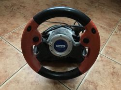
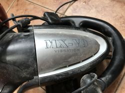
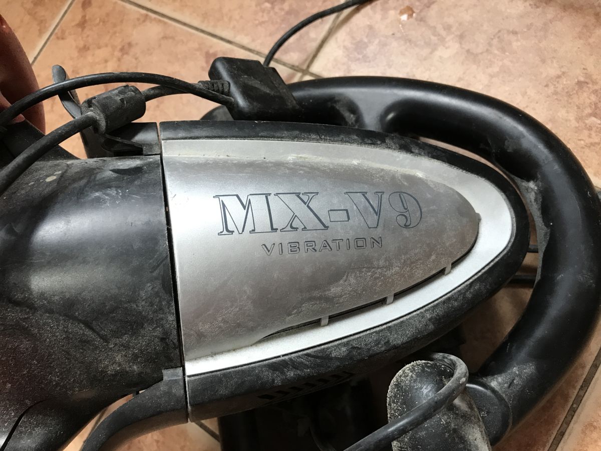
The first piece of hardware to be showcased is the MX-V9 Vibration steering wheel, which works with either a PlayStation console or a PC via USB. As the name suggests, it is equipped with an additional feedback system via vibration, the mechanism of which we will also get to know.


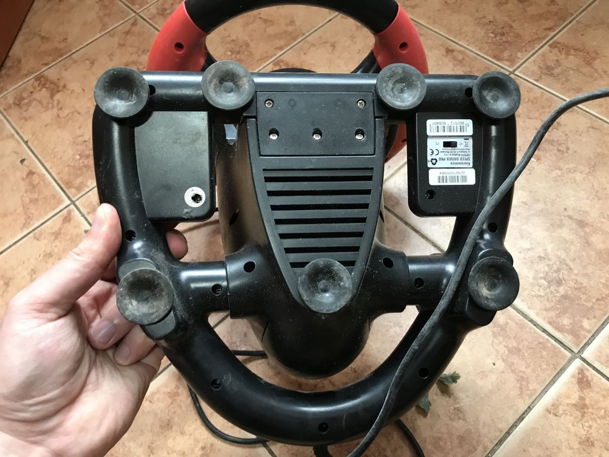
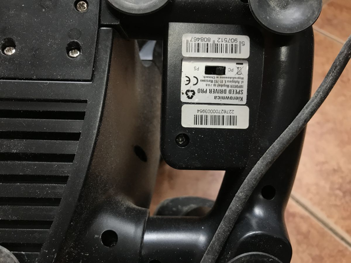
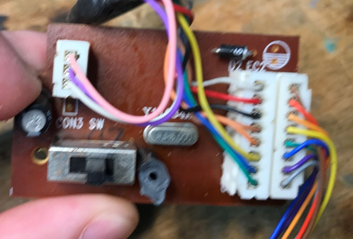
Importer - Megabyte, manufacture in China. There is a Playstation/PC switch on the bottom.

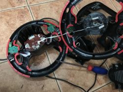
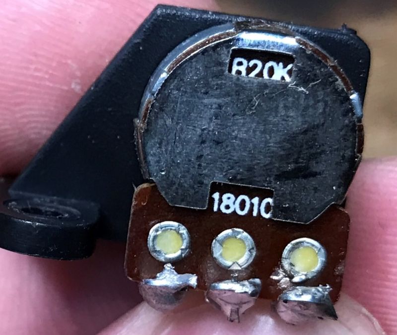
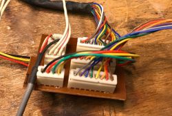
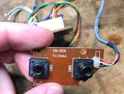
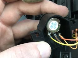
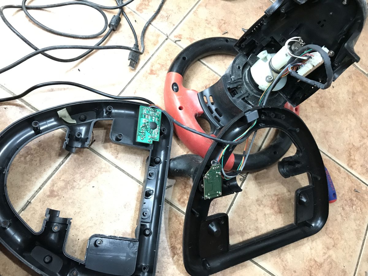
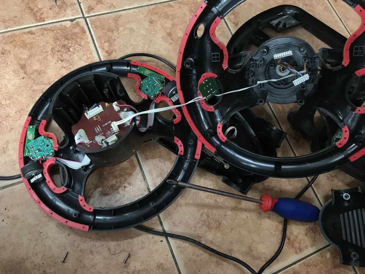
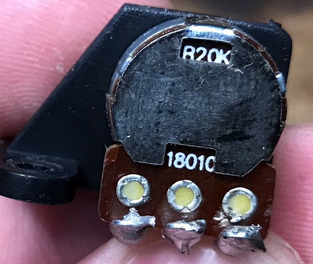
The whole thing is held together by countless screws. You can tell by the PCB inside that the hardware is quite old. I was surprised that the separate modules are on plugs, probably this is from before the cost cutting. You can also immediately see how the steering wheel deflection is measured - it's just a potentiometer.

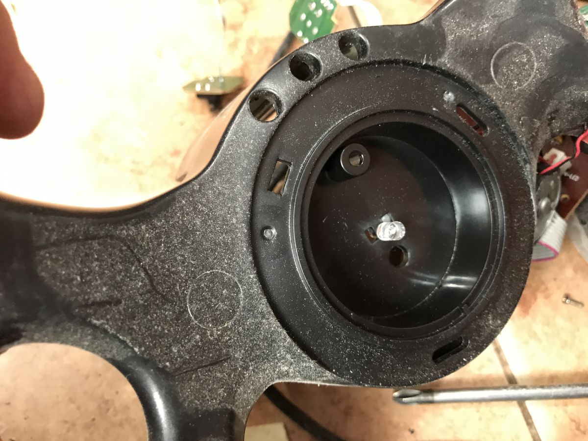
The LED is mounted via hot glue:

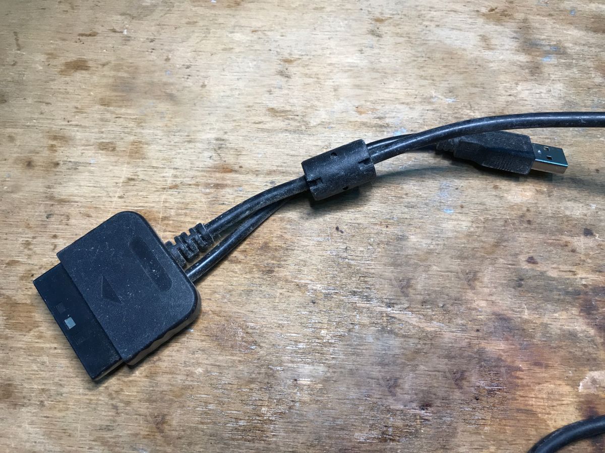
Here's another cable mentioned - Playstation or USB:

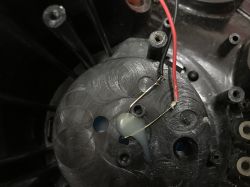
As for this potentiometer, it is linear, 20 kΩ. The letter B stands for linear. Type A - logarithmic - is also popular, e.g. for audio, but it wouldn't make sense here.
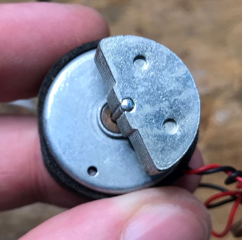
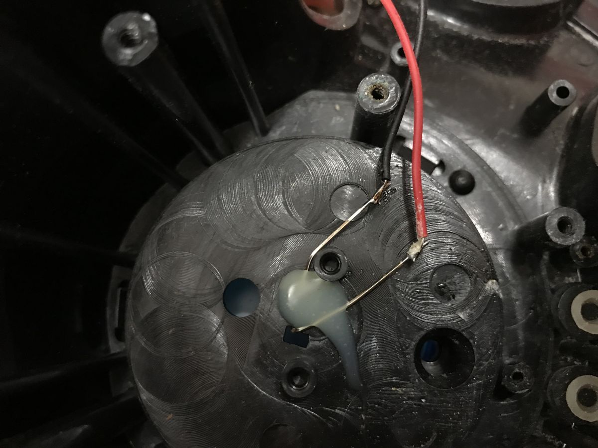
Now for the vibration issue - these are created by motors with unbalanced weights.
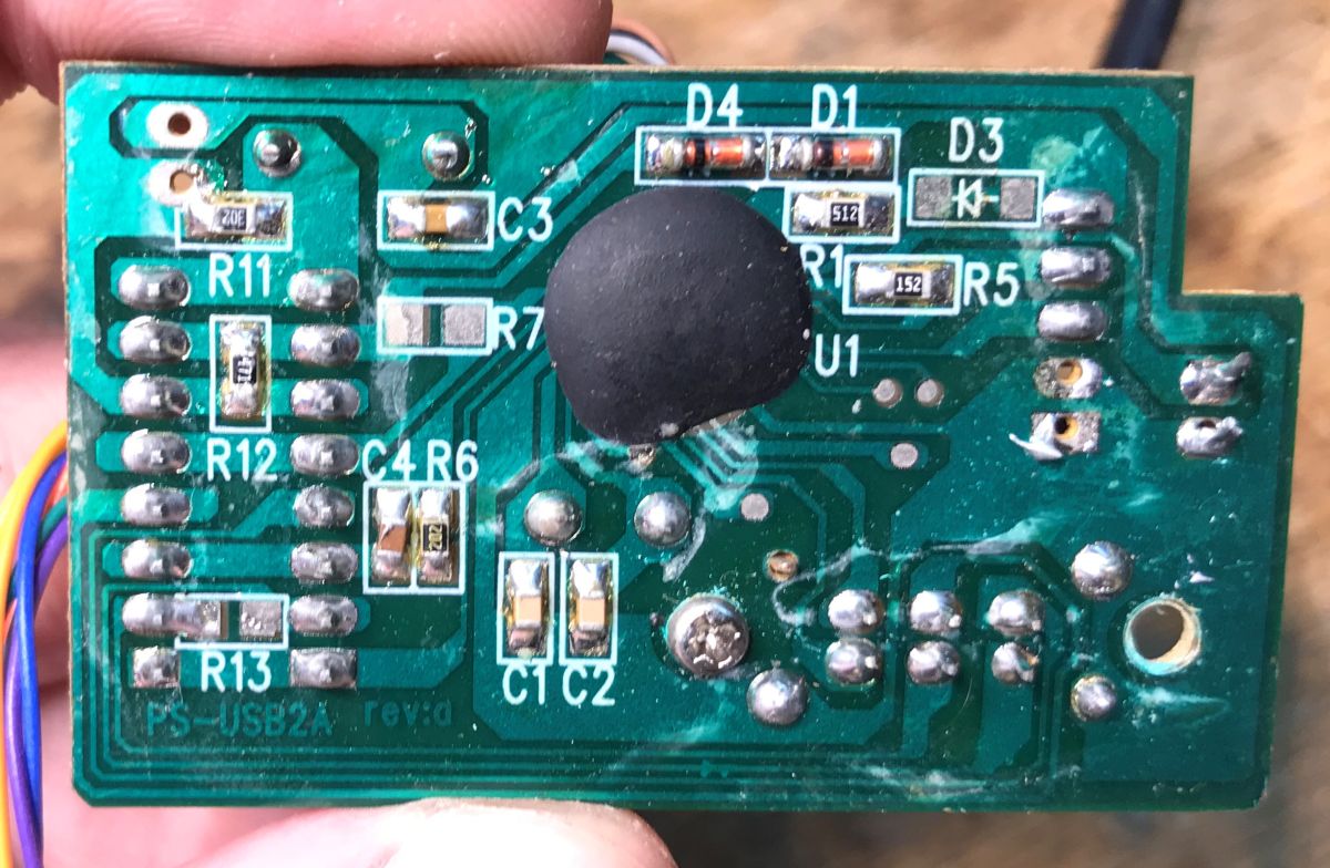
Unfortunately the rest is less interesting, there is the famous "black dot" on the board, it is impossible to know what circuit it is:
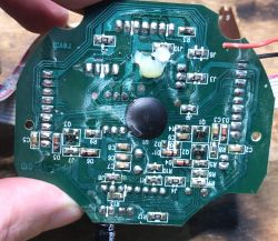

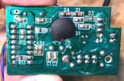
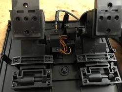
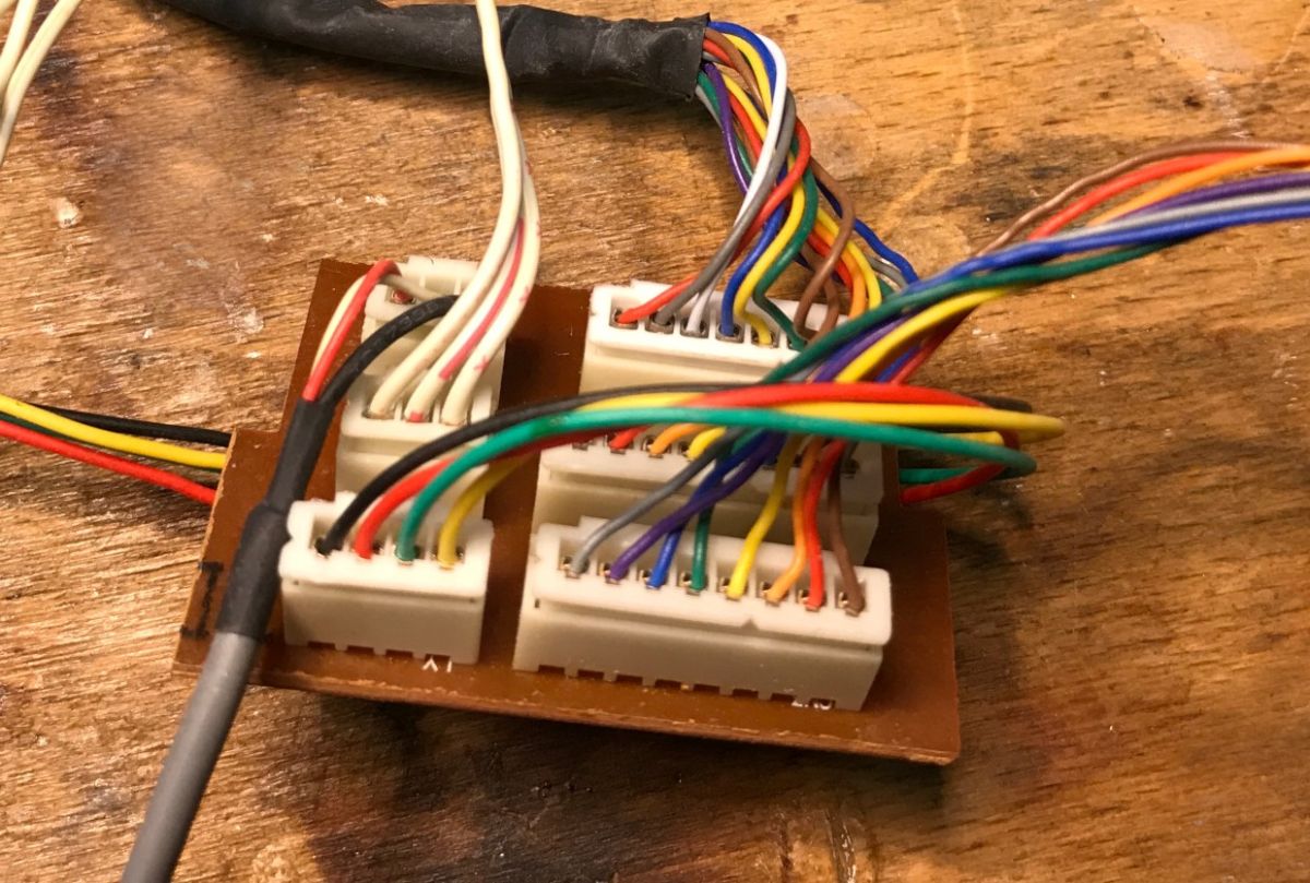
All the electronics from inside:
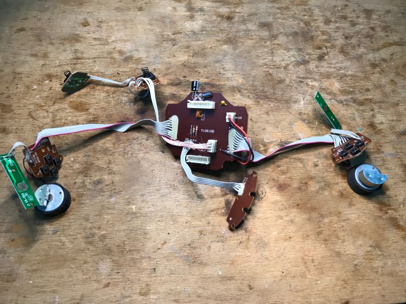
All electronics from inside
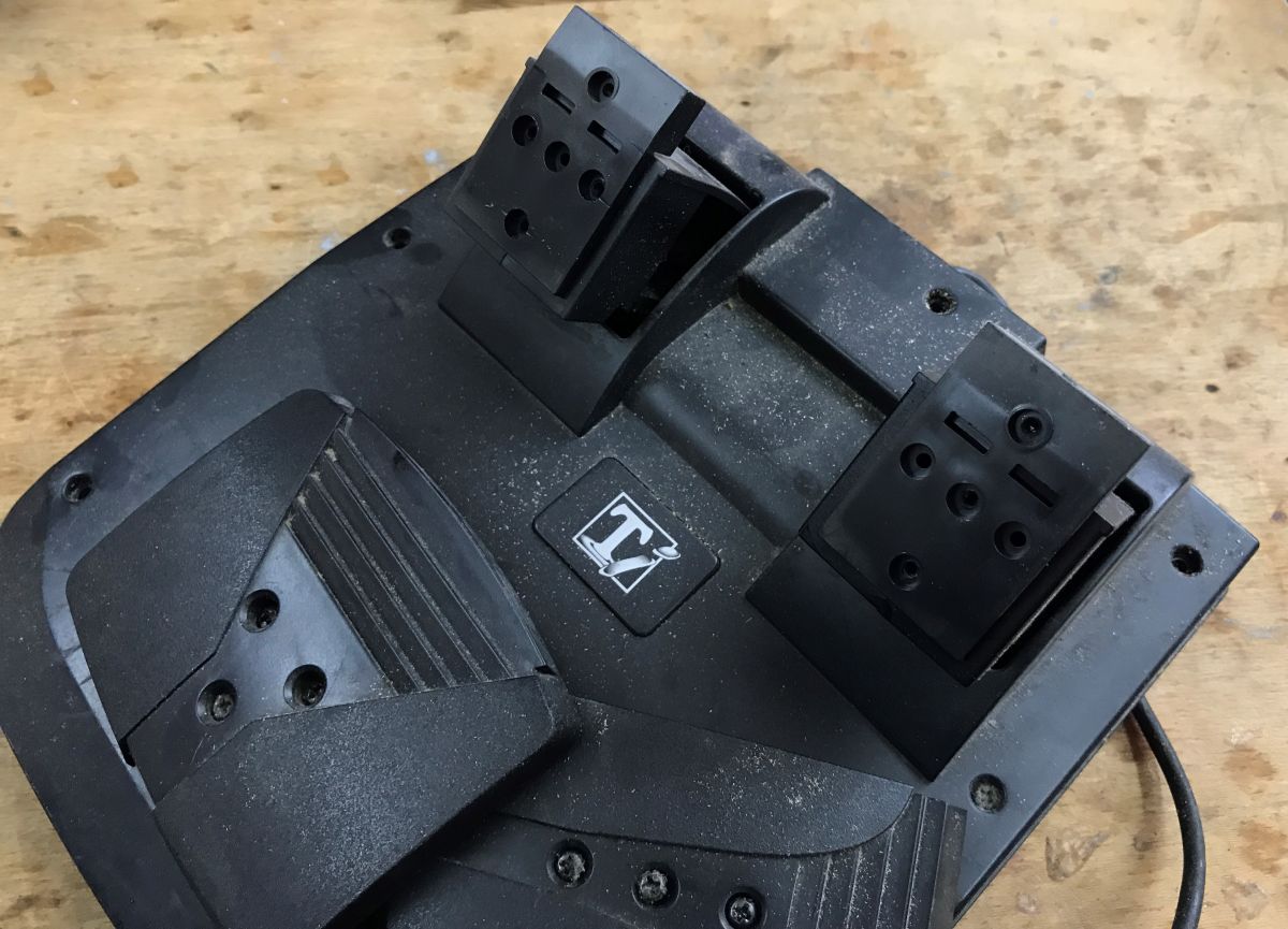
Now the second part of the presentation - PS/2 pedals.
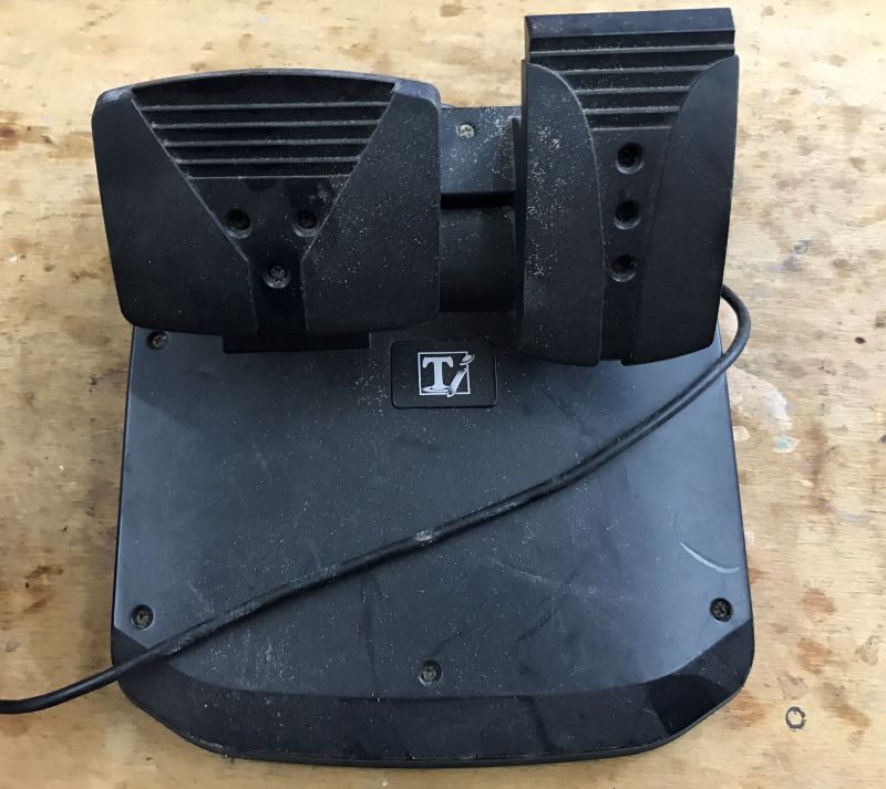
Will the situation be different here? What measures the level of throttle depression?


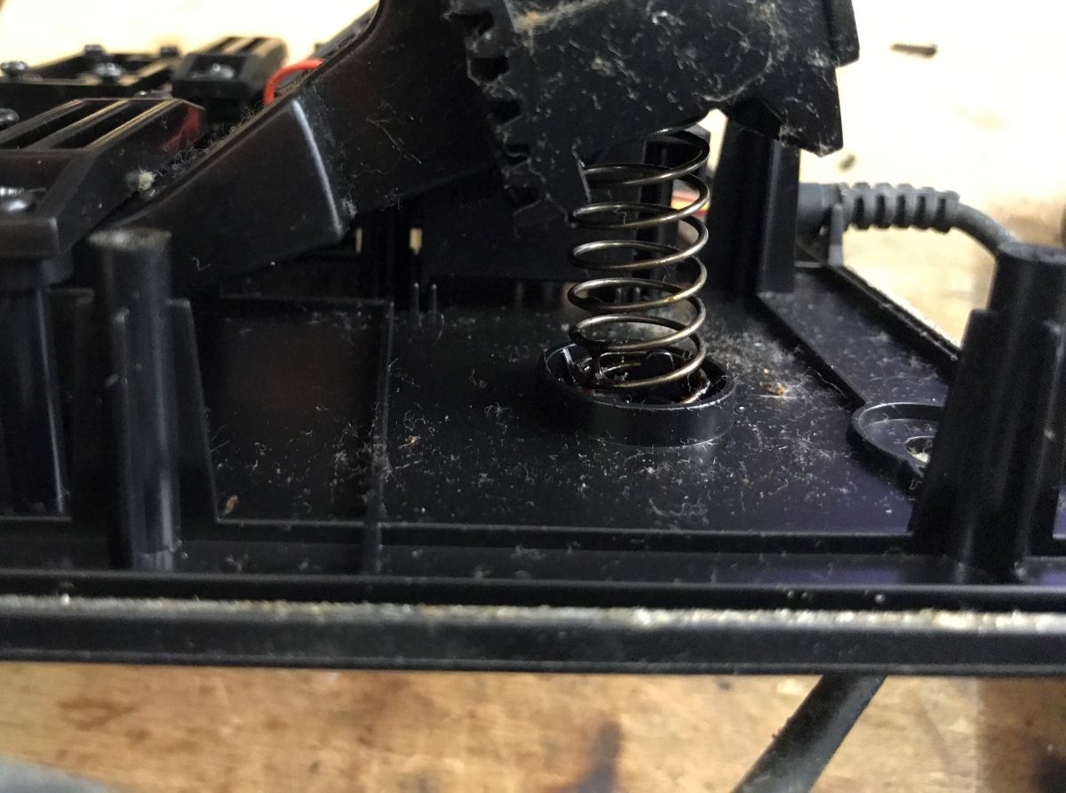
We take a look, and it turns out that the whole mechanism is a spring + potentiometer.

By the way, I don't see a controller here, so maybe this connector didn't go directly to the computer.... but that's a secondary issue.
Summarising , it's all just based on buttons (zero-one state - pressed or released), potentiometers (as a voltage divider - reading from the ADC) and possibly digital outputs to turn on/off LEDs and motors. There is not much philosophy here.
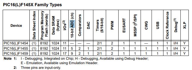
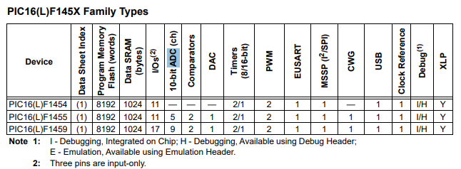
It should be possible to bring this to life with
PIC , there are enough ADC channels, input pins reasonably too:
There is nothing left to do but to rewire the acquired electronics under the PIC and prepare the USB descriptors. This I will already show in the next topic.
Have you ever created your own joystick/gamepad project based on a microcontroller? 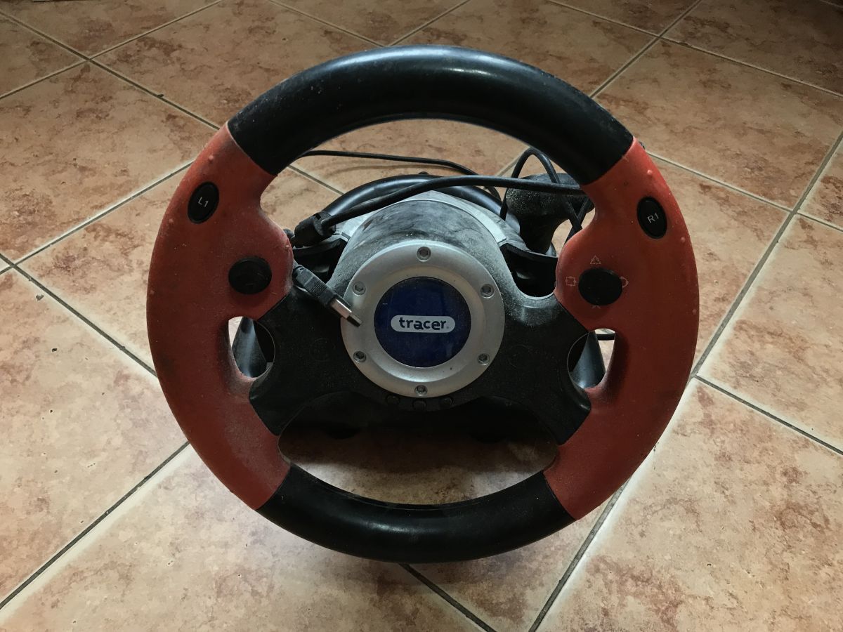


Comments
The pedals were usually connected to the steering wheel. i don't see a socket in the steering wheel here, so maybe it's not a kit [Read more]
I confirm, these are two pieces of hardware from different sources. I just kept them with the idea of using the PIC. If something moves, I'll show it in the DIY. [Read more]
There are already projects on the web for making your own controller based on an old steering wheel or something like that. I just made one on the same steering wheel, only I made my own pedals, because... [Read more]