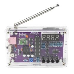
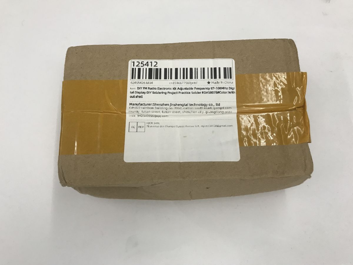
What kind of soldering kit for a beginner? The HU-017A kit shown here costs just under a dozen zloty, and you can get it even cheaper in a promotion. It allows you to build a simple FM radio based on a ready-made RDA5807S module, a microcontroller with a 7-segment display for tuning and a TDA2822M audio amplifier. A slightly more expensive version with an enclosure is also available.

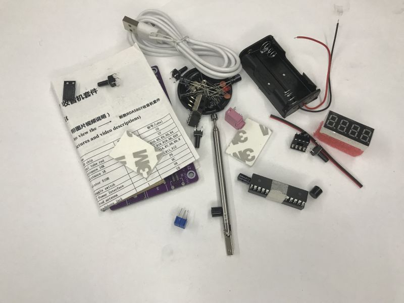
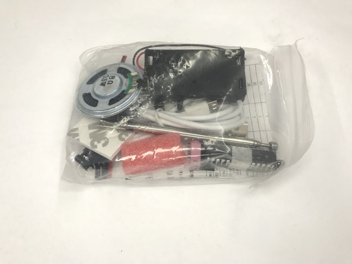
Let's start with the contents of the kit. I got mine in a promotion, I paid about 10 PLN. Let's see what's inside:

Loudspeaker and antenna you know, components and board too, but they even gave a battery basket and USB cable. Not bad.
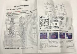
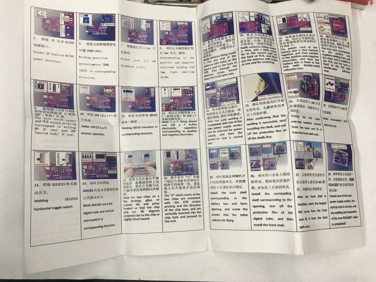
The seller has thought of everything - there is even a bilingual manual. For this reason, I will shorten my argument a bit here, but will still present the assembly of this radio.

I always start by wiping the tile with isopropanol. Any dirt or grease makes soldering difficult. Hygiene of the soldering iron tip is also important, but the board should not be forgotten either.

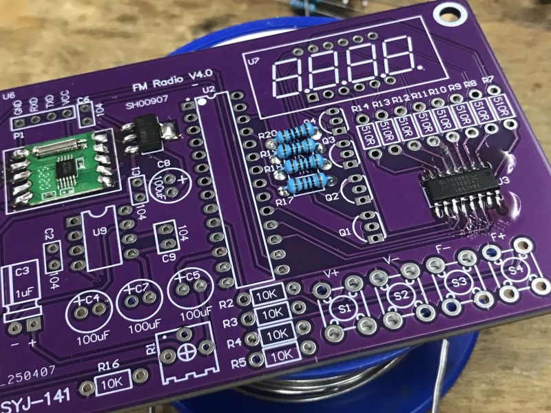
Most of the components are assembled by threading, although there are a few sparse SMD parts. It's best to start with the tiniest circuits, then the soldered ones won't interfere so much with the assembly of the next ones.

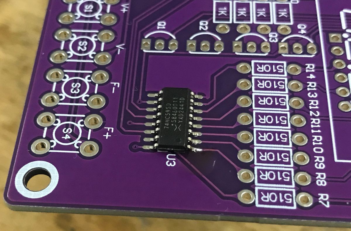
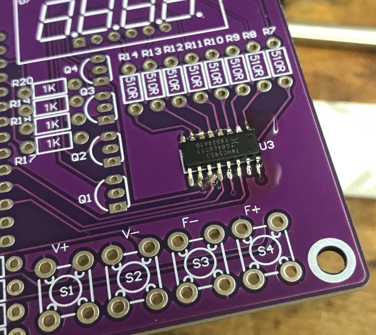
The smallest is probably the 74HC595D sliding register. It allows you to control the display with fewer pins on the MCU side. I discussed it
in a separate topic .

It must be fitted according to the marking of the first pin (dot/cut). My method of soldering is to apply solder (and always a little flux - for convenience) to one pad, then "grab" the chip by one leg, and solder the others. It is important to heat the pad and apply the binder to it - not directly to the soldering tip.

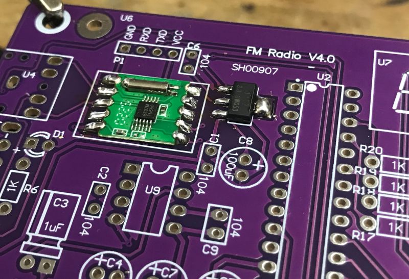
The second thing that needs to be soldered initially is the radio.... or rather the radio module - the RDA5807S. This is the one that receives the radio signals and converts them to audio output, tuning is done digitally via I2C protocol from the microcontroller. Here I have a similar method and again, care must be taken to ensure the correct orientation, you can't solder 180 degrees inverted.

Right next to it you need to solder the LDO that supplies it with 3.3 V, taking 5 V as input. It is also important to have good contact between the component and the large pad, which acts as a heat sink, although in this particular case there is not much heating.
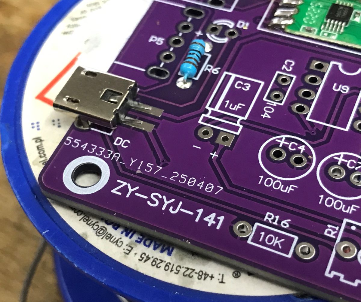
Then one by one - the resistors. You just have to verify them with either a barcode or a multimeter. You can't get the values wrong, here we have two different ones, 10kΩ and 510Ω.
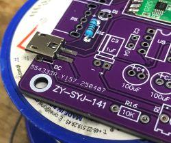
Of the SMD components, there is still the USB socket, or rather, its contacts are surface-mounted and the legs are threaded.
With electrolytic capacitors and transistors you also need to take care of polarity.


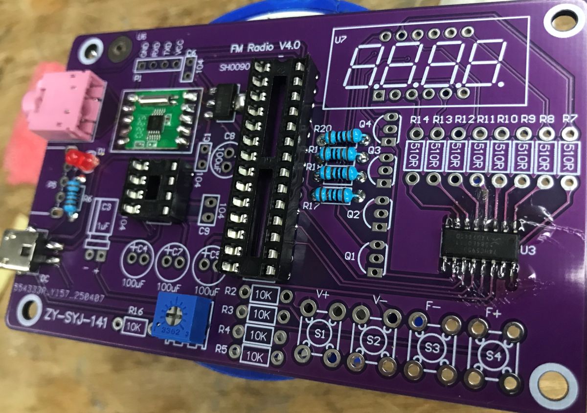
Finally I also solder the bases, here again taking care of the orientation, although for the base itself it is a purely cosmetic matter, however a reverse soldered base would be misleading. Then I dogleg the legs of the components (MCU and amplifier) and put them in the bases.

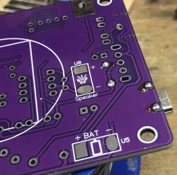
Still remains to solder the speaker (I take the wires, pads and solder), mount the antenna and it's time for the final verification of the solders and connections. Just for the record - the radio works straight away.
Finally, we will quote the schematic of the radio (almost - because in the topic there is a version with a register and here without):

The radio from the HU-017A kit consists of several simple functional blocks. The power supplied from the USB or DC socket is stepped down and stabilised by the AMS1117-3.3, which provides 3.3 V for the electronics. The main controller of the unit is the STC8K17 microcontroller, which operates the buttons, display and communication with the FM tuner. Station reception is performed by the RDA5807S module, which receives the signal from the antenna and, via the I2C bus, is tuned by the microcontroller. The current frequency is displayed on a four-digit 7-segment display controlled by a 74HC595 shift register. The audio signal from the tuner goes to the volume control potentiometer and then to the TDA2822 amplifier, which drives the speaker. Pushbuttons allow you to change the frequency and control the radio, and an LED indicates power to the unit.
So what is the problem with this radio?
Basically none - just buying a "do-it-yourself radio" at some point I'd expect more of a DIY radio receiver, probably still with a coil to be wound (or at least soldered on), and here we essentially have a ready-made FM tuner and solder only its control and amplifier. Only is this really a downside?
The project itself is undoubtedly trivial to get up and running, requires no tuning and will work out of the box. Just right for a beginner's first start.
Have you also assembled your own radio as part of your electronics learning, and if so, according to which schematic? 


Comments
I see an opportunity to improve this receiver somewhat. On the headphone socket, pins 3 and 4 could be connected. This would allow stereo listening on the headphones and full mono on the speaker (the socket... [Read more]
I also noticed that the mono speaker is only the right channel. But channel summing is not done by shorting the outputs! Has the colleague checked the datasheet of the circuit? After all, these are outputs... [Read more]
I understand that the battery cage is linked to the battery supply. Where is this connected and what does this option look like? [Read more]
There is a little bit of nerdiness, as with any working "self-assembled" device. But it doesn't add any knowledge. Even a long-wave detector on a germanium diode gives an incomparably greater injection... [Read more]
Look at the price o evaluate the cost-effectiveness. It is always some youngster who will be infected by the passion of soldering and electronics. Our Polish kits also consisted of soldering a board with... [Read more]
And that is how it is supposed to be. People are supposed to consume and they are not supposed to want to count or know how to count. An excess of knowledge in society would upset the age-old proportions... [Read more]
it's not about consumption - I used to make PCBs with oil paint and a matchstick and a carpet spilled from ferric trichloride--a 1mm drill bit put into a 500W Celma drill--now that's a gulf. I'm leaving... [Read more]
This is how it was done, the chloride I probably still have in the boat in granule form. [Read more]
A'speaking of just the schematic. I don't think it's very educational (and this is, among other things, the role of the set) that the signal counting from the left goes into the speaker, and from the right... [Read more]
Gosh, and in the days before self-assembly kits (1980s "Młody Technik", "Radioelectronic"), who counted anything? He would redraw from an article in a monthly magazine a finished picture of a circuit board... [Read more]
I have never in my life redrawn a finished pcb design from Radio Electronics or MT. And 'whatever counts' I learned very quickly and since then more and more a percentage of each realization was mine and... [Read more]
A colleague first learnt "to count anything" (and very quickly, according to him) and then made the first board according to his own design. And others proceeded in a different order and for them there... [Read more]
Again: the only thing I was referring to is that this kit teaches no one anything, has no educational value. And I am not judging the motivations of the purchasers. What came out completely by the way... [Read more]
For beginners it is good - put together, there is a chance it will work and it is for this radio, not some blinker on diodes and 2 transistors. In my case, the control of the lights was implemented on... [Read more]
A small but important point: you have to learn from books. Errors in practical experience will occur anyway, they are unavoidable. But they should provide the impetus for learning and not be the basis... [Read more]
It is a fact. Theory is a matrix for calculating the parameters of a transistor. A truth table for miimising functions in digital circuits, etc etc etc. Some practice is repair, measurements. And here... [Read more]
Full agreement with both Colleagues. But this is effectively countered by the fundamental principle of modern education "school is supposed to give skills, not knowledge". This mantra emerged at the turn... [Read more]
I must comment - I agree 300%. One can then read posts where one does not see that one is referring to the sine lun tangent of an angle explaining that the cosine of the same angle is no longer the... [Read more]
I would definitely not blame the education reform for the current state of affairs. The reform was certainly not perfect, but it was necessary. For formal reasons it was necessary to adapt the Polish system... [Read more]