logo elektroda
logo elektroda
X
logo elektroda

Industrial ESP32-S3 module with 16 MB Flash, 8 MB RAM, RS485 and CAN buses

p.kaczmarek2  23 2274 Cool? (+2)
Listen:

TL;DR LABEL_AI_GENERATED

  • ESP32-S3-RS485-CAN is an industrial ESP32-S3 module with Wi‑Fi, Bluetooth, isolated RS485 and CAN, DIN-rail mounting, and a PCF85063 RTC with battery backup.
  • PlatformIO setup starts from an esp32-s3-devkitc-1 configuration, then adjusts flash size, framework settings, and CDC mode so Serial.printf works over native USB.
  • The board ships with 16 MB Flash, 8 MB RAM, operates up to 36 V DC, and costs around £80.
  • Demo code shows LED blinking, RS485 transmission using HardwareSerial, CAN communication with TWAI, and RTC access over I2C via the Wire library.
  • A battery keeps the RTC running without mains power, but the DIN-rail housing leaves no external reset button, and RS485/CAN need 120 Ω termination resistors.
AI summary based on the discussion. May contain errors.

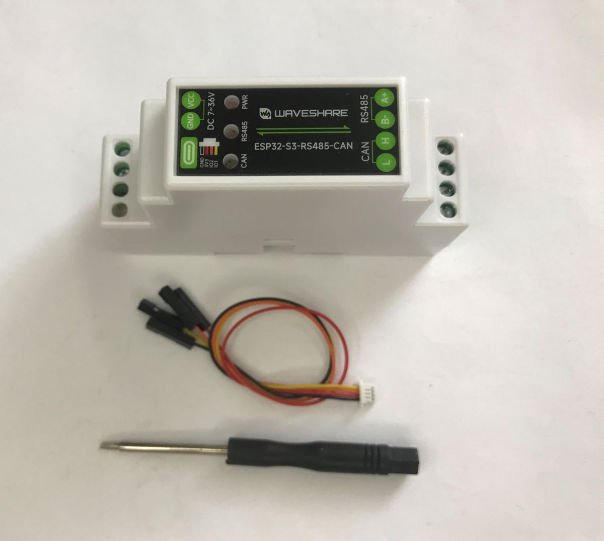
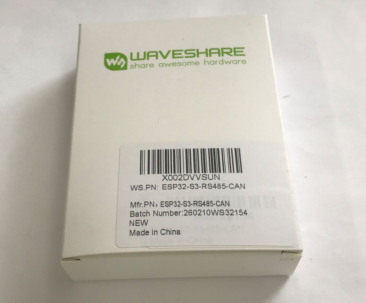
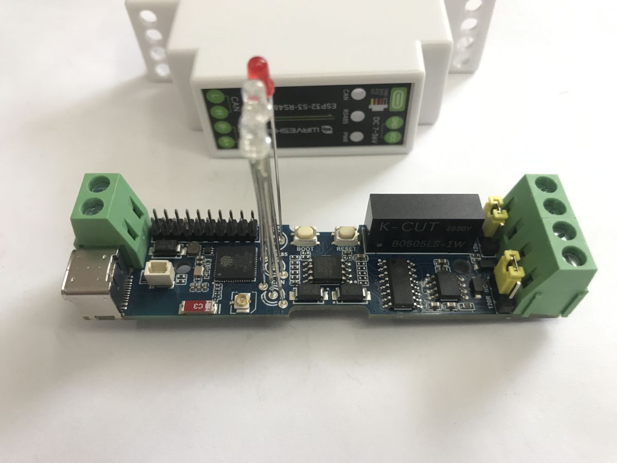
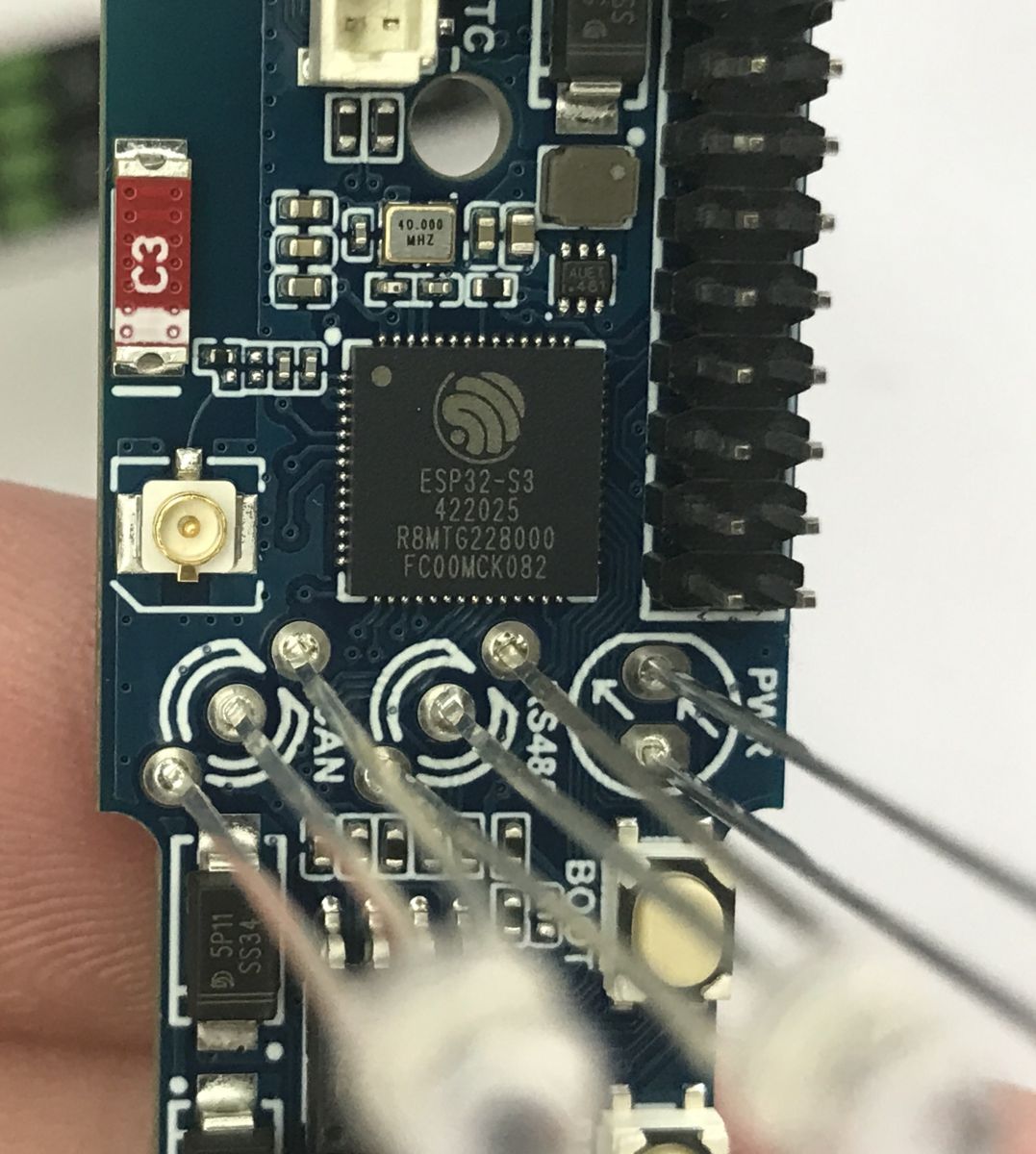
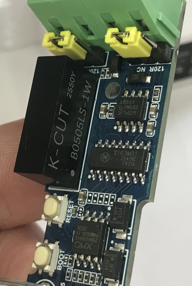
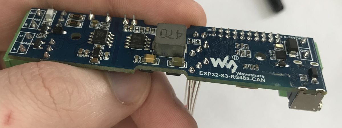
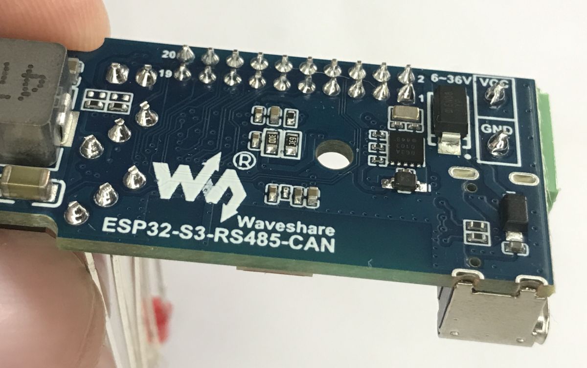
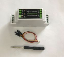
ESP32-S3-RS485-CAN is an industrial module equipped with Wi-Fi and BT communication (thanks to ESP-S3) and isolated RS485 and CAN. It is designed for DIN rail mounting. It operates on voltages up to 36 V DC. Also on board is a PCF85063 RTC to keep time, along with a connector for a battery, an antenna connector and a 20-pin connector. You can buy this module for around £80.
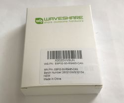
In the kit, we get cables with a connector compatible with the SH1.0 connector, on which 3.3 V, ground, GPIO1 and GPIO2 from the ESP are brought out. In addition, we also get a small screwdriver.
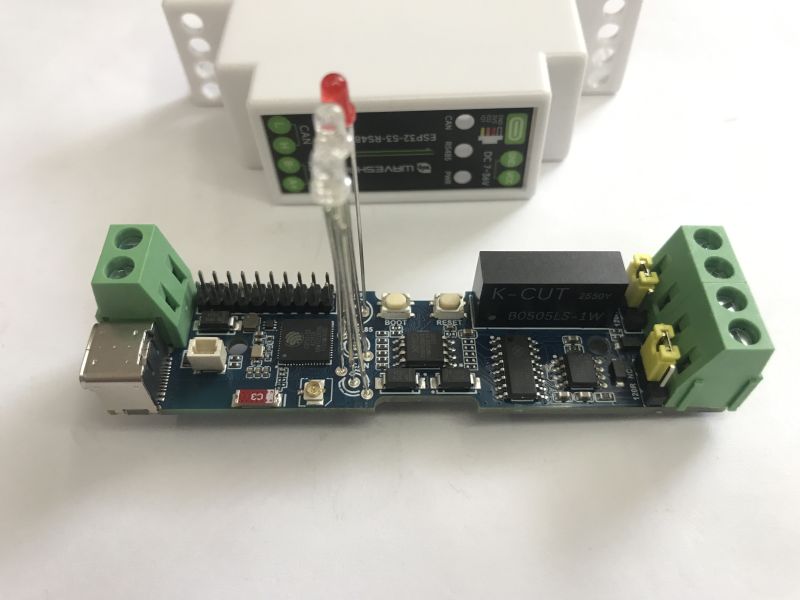
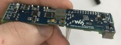
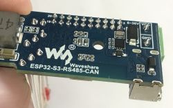
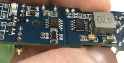
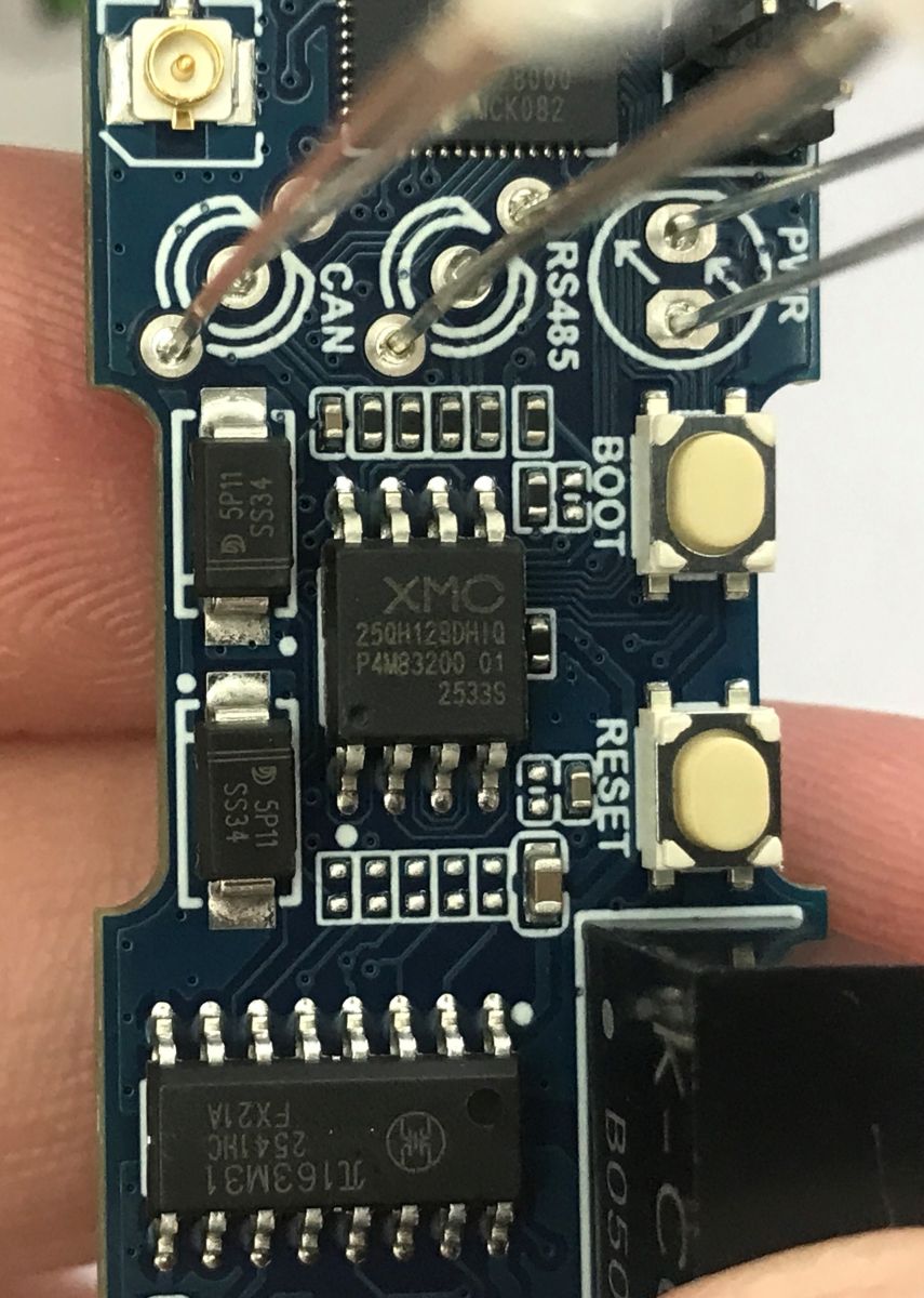
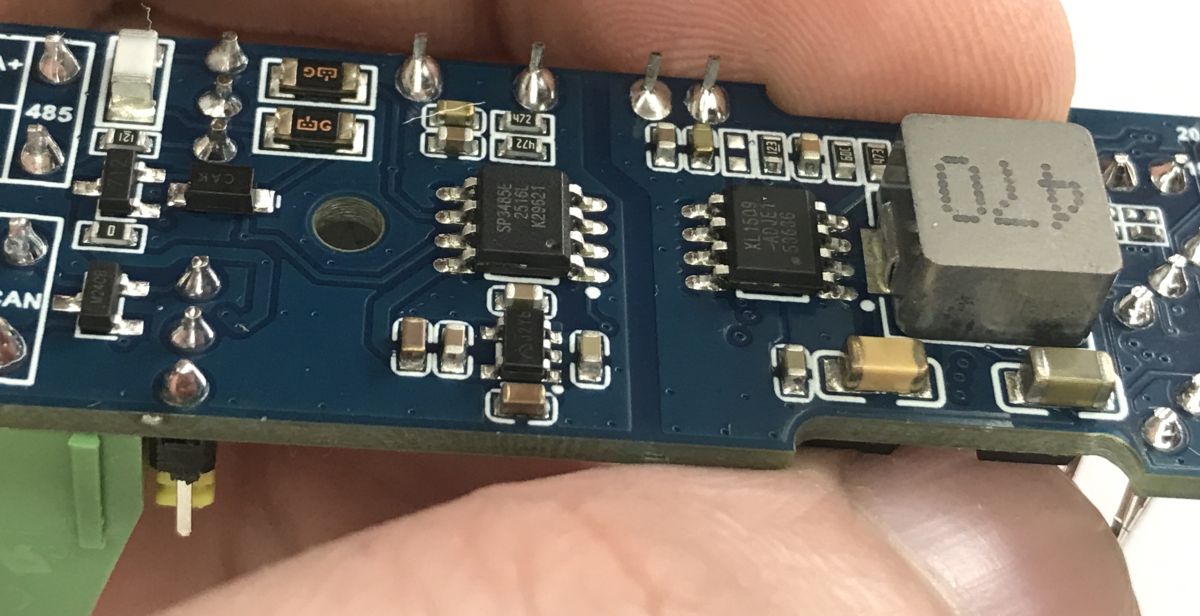
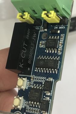
Photos from inside:
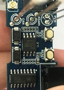
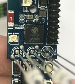
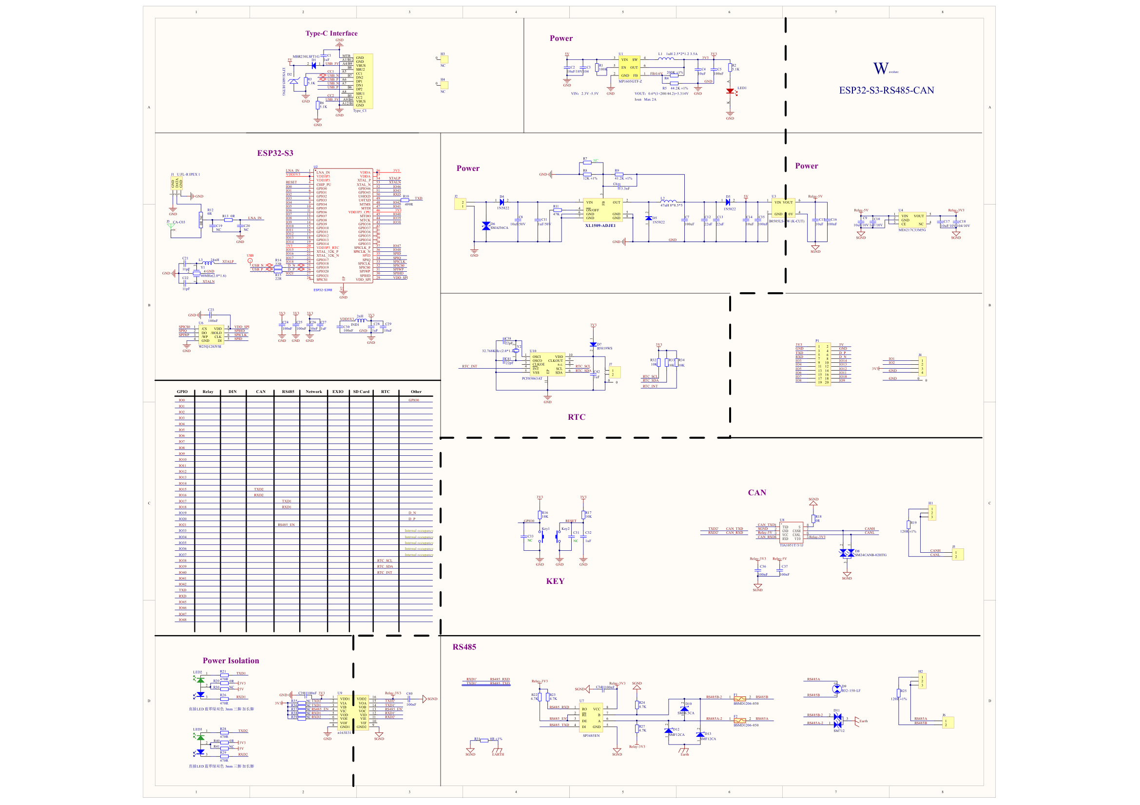
Scheme:
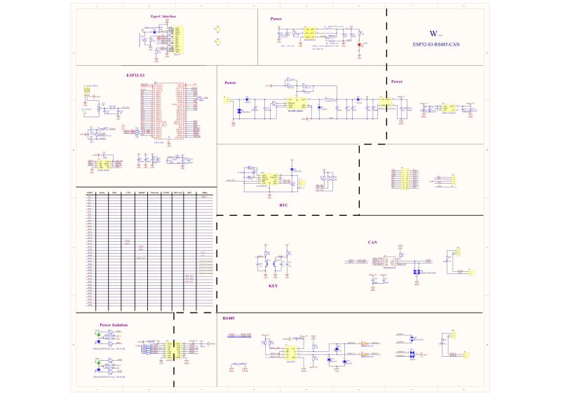
Electrical schematic of Waveshare ESP32-S3-RS485-CAN with power, RTC, CAN, and RS485 sections
Now we can move on to the actual part of the presentation, which is to show how a beginner can get started with this board in the free PlatformIO environment (Visual Code extension).


Hello World (LED flashing)
You need to start with the configuration for the platformio. You can base it on the esp32-s3-devkitc-1 board, but you need to set a few things, including the Flash size and framework.
Code: Ini
Log in, to see the code

It is important to enable CDC mode in build_flags. Otherwise we will not get Serial.printf messages. The board shown does not have a USB to UART converter, but connects directly to USB. The ESP32-S3 supports this in hardware.

Now the actual code of the demo. The whole thing is very simple, it just manually switches the TX/RX pins on and off from both buses. This gets the LEDs to blink.
Code: C / C++
Log in, to see the code


Start RS485 communication
Three pins are required - RX, TX and Enable. Their indexes are marked on the diagram. RS485 is the physical layer of the UART, so a HardwareSerial is sufficient on the ESP. Set the baud, parity bits and pins.
Code: C / C++
Log in, to see the code

The above demo sends a sample write over RS485 and then sends over USB the data received there. In practical RS485 installations, be sure to have termination resistors (typically 120 Ω) at both ends of the bus. Without this, communication errors can occur.


Starting CAN communication
You can use the TWAI library. Here there is no EN pin for CAN, so the matter is further simplified. The rest according to the CAN material:
How to establish a CAN connection between two ESP32s using the LilyGO T-CAN485 example?
As with RS485, the CAN bus should be terminated with 120 Ω terminating resistors at both ends of the CANH/CANL line.


RTC activation
The board uses a PCF85063AT real-time clock connected to pins IO38 (SCL), IO39 (SDA), IO40 (INT). It is a simple RTC communicating over the I2C bus, so you only need the standard Wire library to operate it. The package structure is simple enough that a separate library for PCF is not needed. Only auxiliary functions for the BCD encoding standard are needed.
Code: C / C++
Log in, to see the code

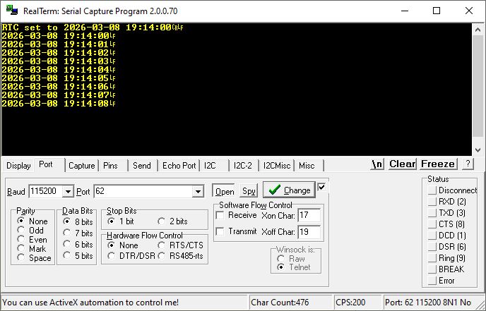
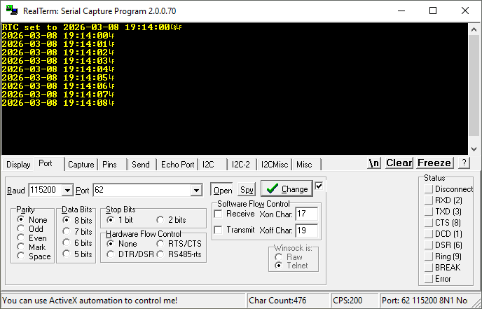
Result:
RealTerm screenshot showing RTC log: time 2026-03-08 19:14:00 and subsequent seconds
In a practical situation, the current time is set once and the RTC maintains it thanks to the battery even when the main power supply is disconnected.

Summary
This industrial module is not only distinguished by its combination of wireless (Wi-Fi and Bluetooth) and wired (RS485, CAN and UART) communications, but also by its affordable housing. Many DIY designs suffer from a lack of good mounting options and implementation is problematic. Here, this problem does not exist, we immediately get a compact DIN rail mountable housing.
An additional plus of this module is the RTC clock - this means that preloaded schedules and automations can work even when Wi-Fi and Bluetooth fail and there is no way to download time from the internet via NTP. This also makes it possible to use the module in places without a permanent Internet connection by programming the time once at installation (e.g. via Bluetooth), as afterwards the time will be kept by the RTC with the battery.
On the other hand, I see one big disadvantage, however, from the mere addition of the housing, namely that the buttons are not extended outwards and there is no way to simply reset the board once it is mounted on the DIN rail.


About Author
p.kaczmarek2
p.kaczmarek2 wrote 14770 posts with rating 12913 , helped 659 times. Been with us since 2014 year.

Comments

gulson 27 May 2026 11:46

Interesting, I'm curious if anyone would dare to implement ESP32 in factories/production lines. It's known, it would be a cheap solution, just how security, maintenance, reliability. I'm curious if anyone... [Read more]

krzbor 27 May 2026 15:12

When I started reading about the features I immediately thought of a price well over 100PLN. And here's a surprise: 80PLN and in Polish shops. The circuit seems ideal as an RS/CAN to MQTT converter. Such... [Read more]

gulson 27 May 2026 15:17

Surely no one in the industry can afford Wi-Fi :) And beyond that? I'd be a bit afraid on a production line, even over Ethernet. [Read more]

altar3 27 May 2026 17:29

Ethernet is now becoming an industry standard. Manufacturers such as B&R rely on ethernet between the CPU and the legs, there are valve islands with ethernet communication. Even many companies are... [Read more]

Mateusz_konstruktor 27 May 2026 20:03

In my opinion, this is a perfectly normal solution in equipment with an industrial purpose, and even organisationally and legally required. There can be no free access, although at the same time we have... [Read more]

gregor124 27 May 2026 20:42

What is the maximum current that can be drawn from this connector according to the manufacturer? [Read more]

Szymon Tarnowski 28 May 2026 00:30

What is the "industriality" of this module? It looks cool, but just because it can be DIN-rail mounted doesn't mean it's of industrial quality, industrial design or has to comply with industrial stand... [Read more]

p.kaczmarek2 28 May 2026 06:18

I would love to see, maybe it would be possible to look inside too? We have an appliance interior section... From which connector? SH1.0? It's a GPIO from ESP, so check this in the ESP datasheet... [Read more]

gregor124 28 May 2026 08:50

Perhaps I asked the question incorrectly. I was referring to the maximum current guaranteed by the manufacturer from the pins from the socket marked J4 pin 3 and 4 (3V3 and GND) in the diagram. Unfortunately... [Read more]

Mateusz_konstruktor 28 May 2026 14:12

Where is the Bluetooth antenna located? [Read more]

Chris_W 28 May 2026 14:20

Esp uses alternately the same antenna. [Read more]

Mateusz_konstruktor 28 May 2026 14:28

@chrisw And where, physically, is this antenna located? [Read more]

electro 28 May 2026 14:35

A red SMD element labelled C3, unfortunately to use an external antenna I have to solder a resistor https://obrazki.elektroda.pl/5221669700_1779971752_thumb.jpg [Read more]

elukam 28 May 2026 18:29

There's nothing to get excited about. It's just another board with ESP stuffed into a case. This has the commercial status of a "do-it-yourself kit", otherwise it would be an illegal product, i.e. a CRIMINAL... [Read more]

filipcichowskidev 28 May 2026 20:58

The introduction of such a module for sale is material for administrative proceedings, not a criminal case. A bit of an offtopic, but this is the umpteenth time I've seen the opinion circulate among... [Read more]

gregor124 28 May 2026 21:31

The problem is that these modules are manufactured and sold in China, so such a law is just as effective in enforcing it as an intellectual property law in China. Of course, if someone has millions of... [Read more]

elukam 28 May 2026 22:12

I used to be interested in the subject and I remember from those days that self-assembly kits and their components are not subject to testing. This does not mean that they can contain hazardous substances... [Read more]

altar3 29 May 2026 05:50

p.kaczmarek2 These are some pictures of the Allen-bradley equipment at the moment I don't have the opportunity to take any more pictures and I'm going on holiday now so I have to put the phone pictures... [Read more]

p.kaczmarek2 30 May 2026 11:45

@altar3 interesting, then I look forward to it, preferably as a separate topic to "Interior of appliances" @gregor124 it's probably best to check on the schematic. As far as I can see, the power supply... [Read more]

FAQ LABEL_AI_GENERATED

TL;DR: At about £80, this DIN-rail ESP32-S3 module solves a real control-cabinet problem: mixed wireless and fieldbus connectivity. One poster called it "ideal as an RS/CAN to MQTT converter". It gives you 16 MB flash, 8 MB RAM, isolated RS485 and CAN, plus an RTC for offline timekeeping, aimed at makers, integrators, and industrial test deployments. [#21910810]

Why it matters: This FAQ helps you bring up the board quickly, assess its industrial fit, and avoid wiring, reset-access, and bus-termination mistakes.

Cecha Wi‑Fi Ethernet
Przydatność w szafie sterowniczej Dobra do konfiguracji lokalnej AP Lepsza do stałej komunikacji przemysłowej
Opinia z wątku „Nikt w przemyśle nie może sobie pozwolić na Wi‑Fi” „Ethernet staje się standardem przemysłowym”
Typowy scenariusz z wątku Podejście do urządzenia, logi, parametry, serwis Linie produkcyjne, CPU‑I/O, wyspy zaworowe

Najważniejszy wniosek: Największą wartością modułu jest połączenie ESP32-S3, izolowanych magistral RS485/CAN i obudowy na szynę DIN. Największą wadą jest brak łatwo dostępnego resetu po montażu w szafie.

Quick Facts

  • Moduł pracuje z zasilaniem do 36 V DC, ma Wi‑Fi, BT, izolowane RS485 i CAN, a także zegar PCF85063 RTC z gniazdem baterii podtrzymującej. [#21910810]
  • Konfiguracja PlatformIO z wątku ustawia ESP32-S3, taktowanie 240000000L, pamięć Flash 16 MB, monitor 115200 i upload 921600. [#21910810]
  • Prosty test „Hello World” steruje czterema liniami LED aktywności na GPIO 17, 18, 15, 16, przełączając je co 500 ms. [#21910810]
  • Zestaw kosztuje około £80 i zawiera przewody do złącza SH1.0 z wyprowadzonymi 3.3 V, GND, GPIO1, GPIO2 oraz mały śrubokręt. [#21910810]
  • W praktycznej instalacji zarówno RS485, jak i CAN wymagają rezystorów terminujących 120 Ω na obu końcach magistrali, inaczej pojawiają się błędy komunikacji. [#21910810]

How do I configure PlatformIO for the Waveshare ESP32-S3-RS485-CAN module with 16 MB flash and USB CDC output enabled?

Use the esp32-s3-devkitc-1 profile, then override the key memory and USB settings. 1. Set framework = arduino, board_build.mcu = esp32s3, and board_build.flash_size = 16MB. 2. Add board_build.arduino.memory_type = qio_opi, monitor_speed = 115200, and upload_speed = 921600. 3. Enable USB serial output with -DARDUINO_USB_MODE=1 and -DARDUINO_USB_CDC_ON_BOOT=1 in build_flags. That matches the working setup shown for this board. [#21910810]

What is CDC mode on the ESP32-S3, and why do I need to enable it in PlatformIO to see Serial.printf messages over USB?

CDC mode enables the ESP32-S3 to expose its USB connection as a serial console, so Serial.printf appears over USB without a separate USB-UART chip. "CDC mode is a USB serial interface that lets the ESP32-S3 present logs and console output directly over native USB, using built-in hardware support instead of an external converter." The post states this board connects directly to USB and that without the two CDC build flags you will not see Serial.printf messages. [#21910810]

What's the simplest way to make the RS485 and CAN activity LEDs blink on the ESP32-S3-RS485-CAN board as a Hello World test?

Drive four GPIOs as outputs and light one at a time in a loop. The demo uses GPIO 17, 18, 15, and 16, described as RS485 TX, RS485 RX, CAN TX, and CAN RX. Set each pin as OUTPUT, write all low, then step through them with a 500 ms delay. This is the fastest proof that the board boots, your PlatformIO setup works, and the activity LEDs respond. [#21910810]

How do I start RS485 communication on the Waveshare ESP32-S3-RS485-CAN using HardwareSerial and the DE enable pin?

Use HardwareSerial(1), assign RX, TX, and the DE line, then switch the UART into half-duplex RS485 mode. The example sets RS485_TX to 17, RS485_RX to 18, and RS485_DE to 21. It starts the port at 9600 baud with SERIAL_8N1, calls RS485.setPins(-1, -1, -1, RS485_DE), then enables UART_MODE_RS485_HALF_DUPLEX. After that, the code sends a line every 2 seconds and echoes received characters to USB serial. [#21910810]

Why are 120 Ω termination resistors needed on RS485 and CAN buses, and where should they be placed in a real installation?

They are needed to reduce reflections and communication errors on differential bus lines. The thread explicitly recommends 120 Ω termination at both ends of an RS485 bus and at both ends of the CANH/CANL line. Do not place terminators at every node. The failure case is clear: without proper termination, the post warns that communication errors can occur in practical installations. [#21910810]

What is TWAI on the ESP32, and how does it relate to CAN communication on this module?

TWAI is the ESP32 interface used here for CAN communication on the module. "TWAI is the ESP32 CAN-controller interface that handles frame transmission and reception on a Controller Area Network, using the chip’s built-in peripheral rather than a separate UART-style serial block." The post says you can use the TWAI library and notes that this board has no CAN enable pin, which simplifies bring-up compared with RS485. [#21910810]

How can I read and set the PCF85063AT RTC on the ESP32-S3-RS485-CAN board over I2C with the Wire library?

Use Wire on the board’s dedicated I2C pins, write BCD-encoded time values, then read back seven RTC registers. 1. Start I2C with Wire.begin(39, 38). 2. Clear the STOP bit by writing control register 0x00, then write time data beginning at register 0x04. 3. Read back the same block and convert BCD to decimal before printing. The example sets 2026-03-08 19:14:00 and prints the RTC value once per 1000 ms. [#21910810]

Which GPIO pins are used on this board for RS485, CAN, and the PCF85063 RTC interface?

The thread identifies RS485 on GPIO 17 TX, 18 RX, and 21 DE. For the RTC, it lists IO38 as SCL, IO39 as SDA, and IO40 as INT for the PCF85063AT. The LED test also uses GPIO 15 and 16 for CAN TX and CAN RX activity indication. Those numbers are enough to start basic software bring-up and wiring checks. [#21910810]

Wi-Fi vs Ethernet for industrial controllers based on ESP32-S3 — which approach is better for factories, production lines, and control cabinets?

Ethernet is presented as the better fit for factories and production lines, while Wi‑Fi is treated as acceptable mainly for local setup or service access. One poster says Wi‑Fi is the basic problem in industry and that an Ethernet version would be better. Another adds that Ethernet is becoming an industry standard and cites CPU-to-I/O links, valve islands, and even vendor-made Ethernet switches. Wi‑Fi still fits a cabinet service model where you open the door, connect to the device AP, change parameters, and read logs. [#21911087]

How could this ESP32-S3-RS485-CAN module be used as an RS485 or CAN to MQTT converter for Home Assistant with HA Discovery?

You can use it as a protocol bridge that reads RS485 or CAN data and publishes MQTT topics that Home Assistant can auto-import. A poster says the board seems ideal for an RS/CAN to MQTT converter and mentions connecting devices such as a recuperator. The practical advantage is cost and packaging: around 80 PLN in Polish shops, plus DIN-rail mounting. This makes it suitable for cabinet installs where you want fieldbus I/O locally and smart-home integration upstream. [#21910995]

What is HA Discovery in Home Assistant, and how would it help expose RS485 or CAN devices through MQTT?

HA Discovery is described in the thread as MQTT discovery commands that let Home Assistant recognize exposed devices automatically. That means your converter can publish structured MQTT data from RS485 or CAN equipment and Home Assistant can add entities without manual definition for each one. The post ties this directly to connecting RS/CAN devices to HA through MQTT and gives a recuperator as a concrete example. [#21910995]

Why is the lack of an externally accessible reset button on a DIN-rail industrial module considered a design drawback, and what safer front-panel alternatives are used in control cabinets?

It is a drawback because operators may need a controlled reset after a fault, but uncontrolled front access can also create process and safety risks. The thread argues that restart access should exist, yet require deliberate action, such as a front key switch or a protected reset method similar to controls used in cabinets. It also gives a real failure scenario: after feed loss from an external tank and an emergency stop, the controller may need a reset before the cycle restarts. [#21911156]

What industrial reliability, maintenance, and security concerns come up when using an ESP32-based module in factory automation?

The thread raises security, maintenance, reliability, and networking concerns, especially for production lines. One poster openly questions whether anyone would deploy ESP32 in factories and asks about security and maintenance. Others narrow the issue to communication choices: Wi‑Fi is viewed skeptically for industrial use, and even Ethernet on a production line makes one participant cautious. The practical takeaway is that hardware cost alone does not decide suitability; supportability and predictable operation do. [#21910898]

How much does the Waveshare ESP32-S3-RS485-CAN board cost, and what accessories are included in the kit?

The thread gives the price as about £80 in the main post, while another poster notes roughly 80 PLN in Polish shops. The kit includes cables for an SH1.0-compatible connector with 3.3 V, ground, GPIO1, and GPIO2 broken out, plus a small screwdriver. Those extras matter because they let you power, probe, and prototype quickly without sourcing the first cable set separately. [#21910810]

What is the maximum current that can be drawn from the 20-pin connector on this module according to the manufacturer?

The thread does not provide that value. The only mention of the 20-pin connector in the post is that the board has one, and a later reply asks what maximum current the manufacturer allows, but no answer appears in the supplied discussion. If you need a guaranteed current limit, this thread alone is insufficient and you would need the manufacturer’s documentation outside this excerpt. [#21911174]
AI summary based on the discussion. May contain errors.
%}