





The interior of the RTx-132 electronic timer, Made in Poland (MCY74645?)
TL;DR 
- A teardown of the RTx-132 Polish electronic timer opens two differently branded units, Alstom and Schneider, and examines whether the markings indicate rebranding or a takeover.
- The compact double-sided PCB contains a rectifier bridge, a transformerless power-supply section, two transistors, a relay, and the MCY74645 controller.
- It supports eight ranges from 0.01 s to 120 hours, mounts in an 11-pole socket, and uses a single 5 A relay with two delayed changeover contacts.
- Closer inspection exposed a BC546B, a BD159, a 220 µF 25 V capacitor, and a Relpol RM84-2012-35-1110 relay with a varistor for surge protection.
- The main limitation is the lack of any datasheet or solid public information for the MCY74645 controller.
AI summary based on the discussion. May contain errors.
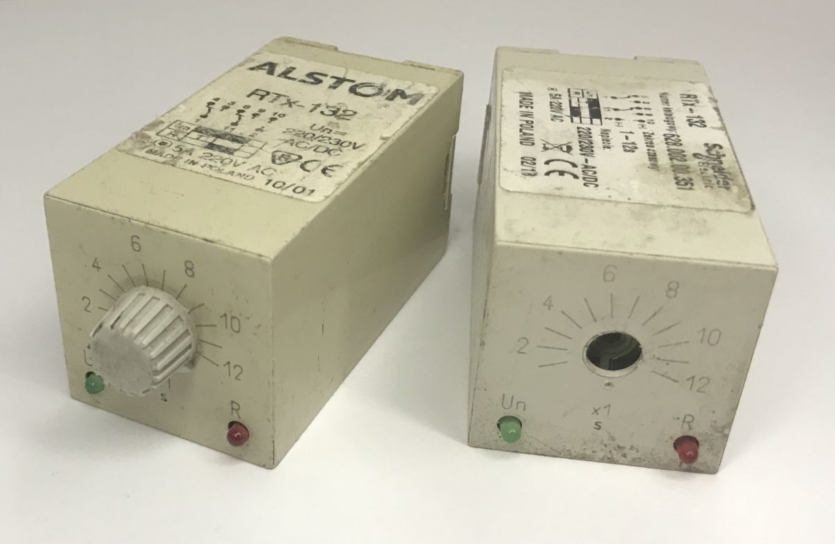
Today we’re taking a look inside another Polish product – this time an electronic timer, a device used to switch a circuit on or off after a set period of time has elapsed. The RTx-132 model shown here offers analogue time setting, is available in eight time settings (from 0.01 s to 120 hours) and in versions for various voltages (12 V DC, 24–48, 60–100, 110/127, 220/230 V AC/DC). It features a single 5 A output relay with two delayed changeover contacts and two LEDs indicating the presence of supply voltage (Un) and the status of the output relay contacts (R). It is mounted in 11-pole sockets with screw terminals or solder terminals. A quick online search shows that it can now be bought for a few hundred zlotys.
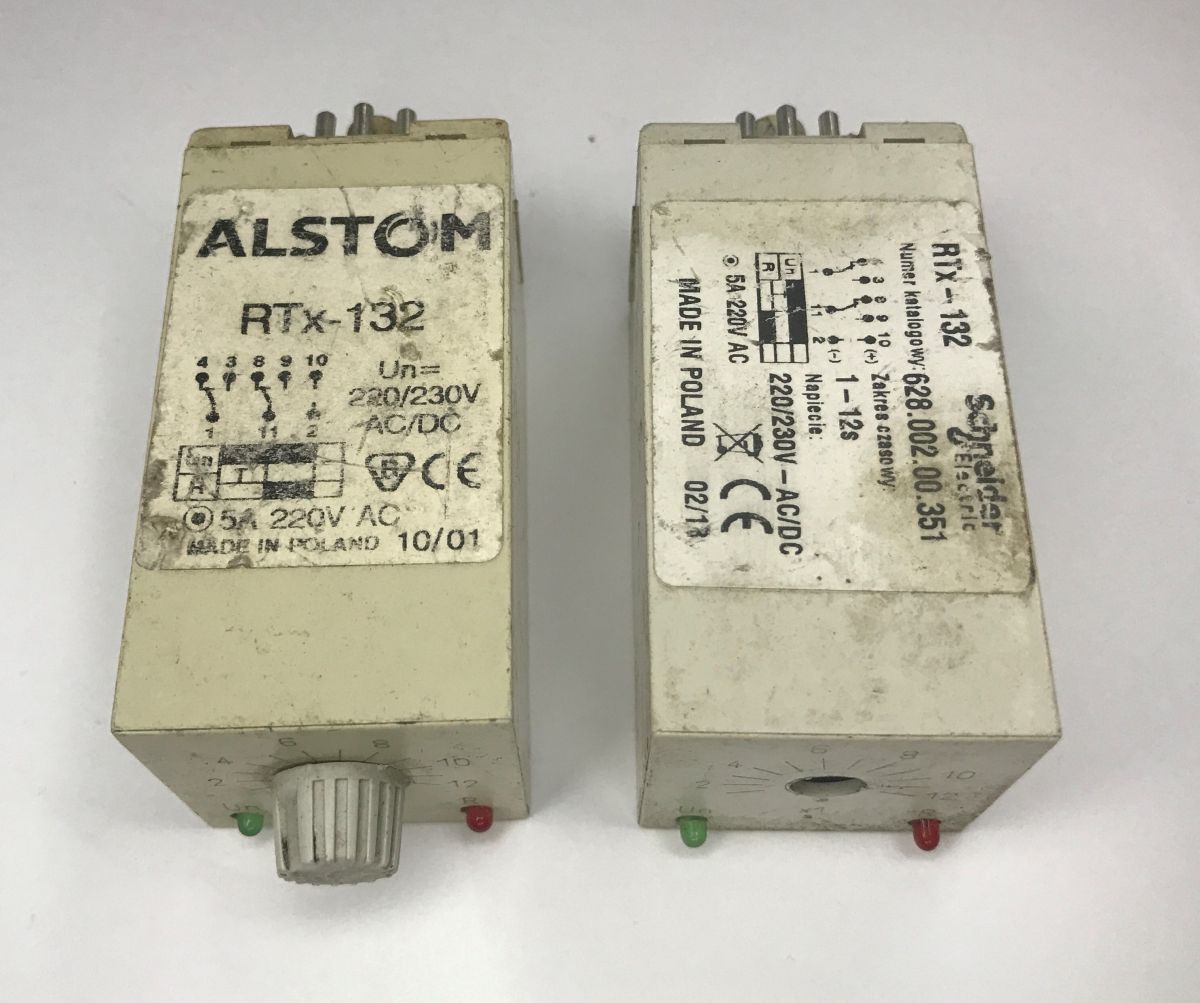
Interestingly, my two units are labelled differently – one as Alstom, the other as Schneider. Could this be a rebranding or a takeover? The markings 10/01 and 02/13 also catch the eye; these are probably the dates of manufacture. 2001 and 2013.
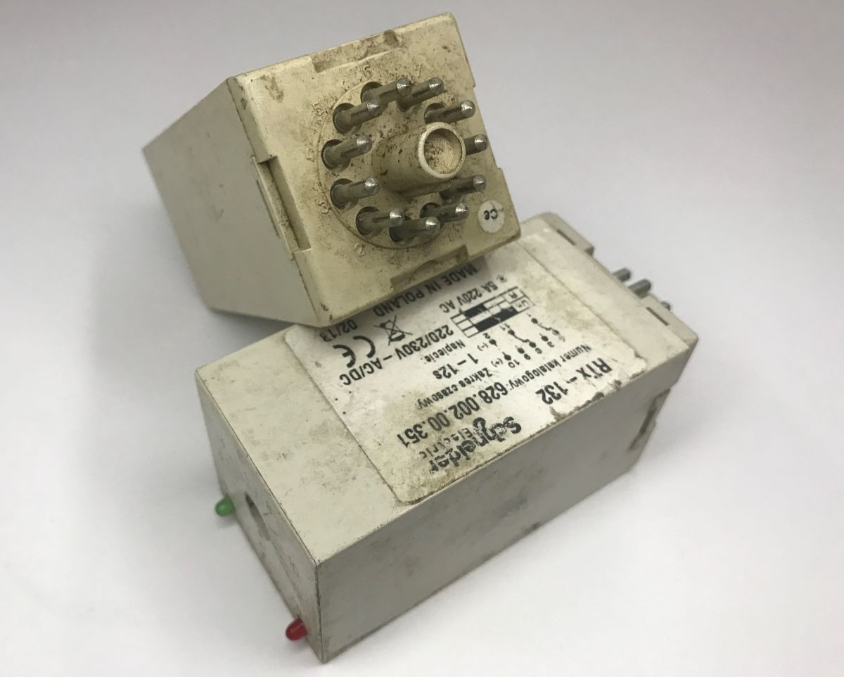
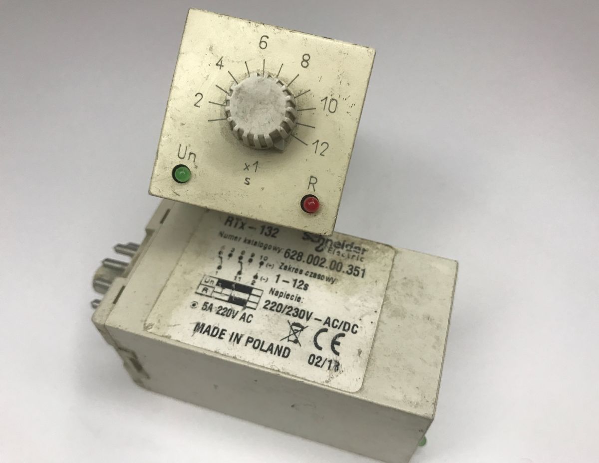
So it’s time to pry open the casing and take a look inside. As I mentioned, this is an electronic timer, so it’s correspondingly smaller than the older, mechanical types. We expect to find a PCB inside.
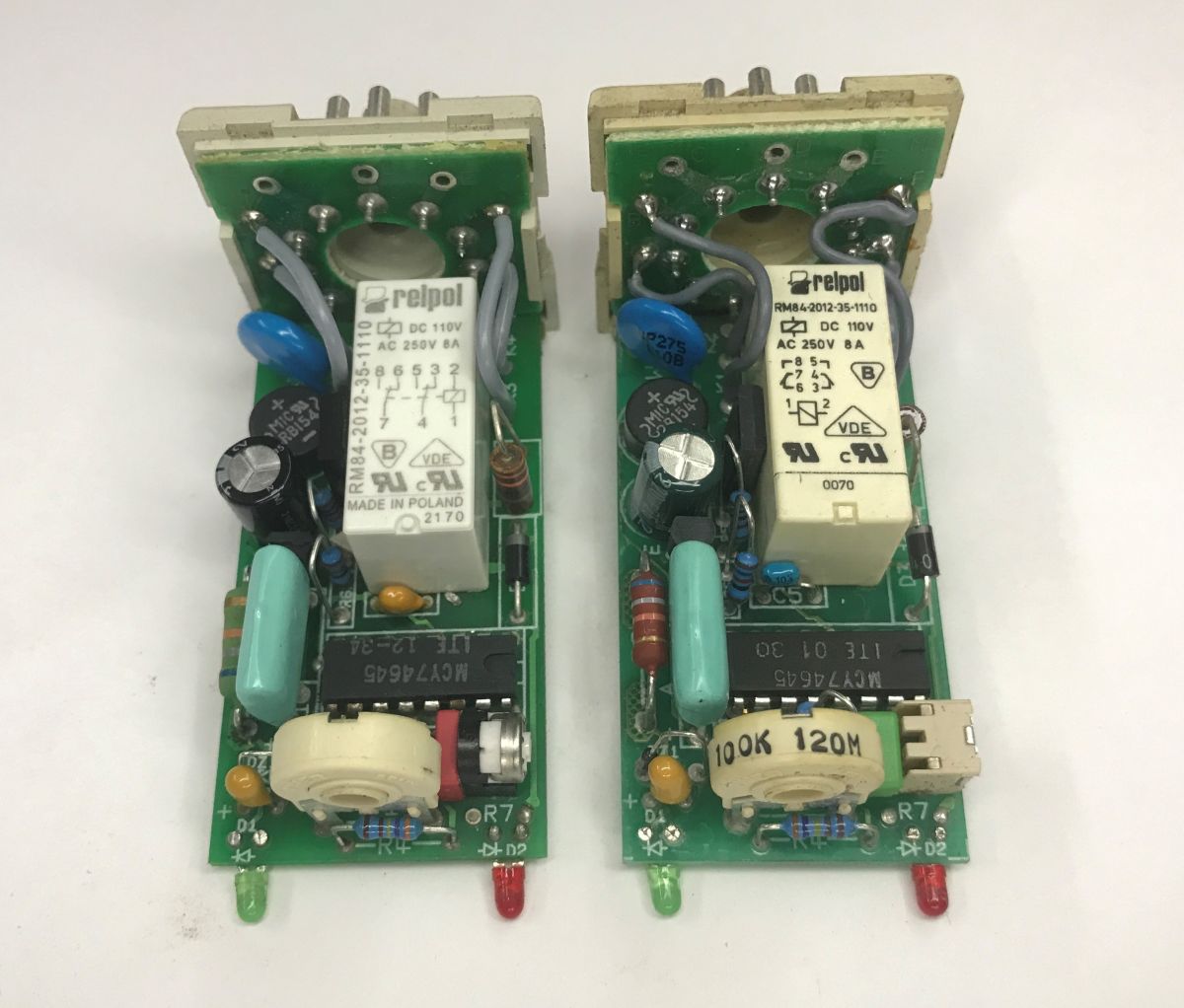
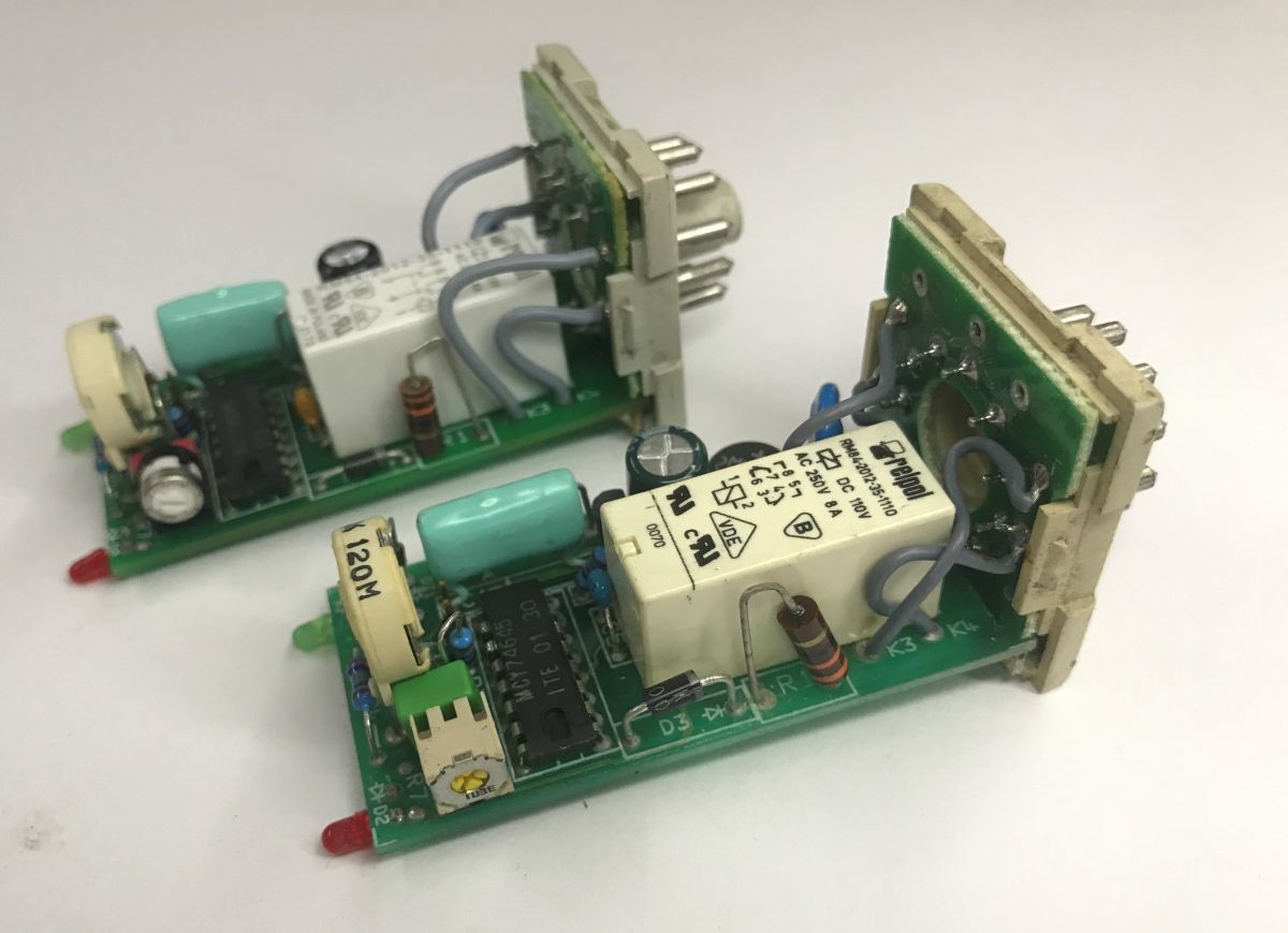
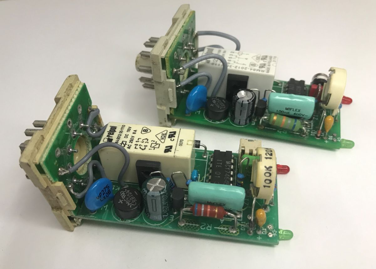
The board is double-sided. Inside, I can see a rectifier bridge, a capacitor, and further on a section with a capacitor and a resistor, which looks like a transformerless power supply. In addition, there is of course a relay inside, two transistors – presumably for controlling the relay – and the main MCY74645 controller.
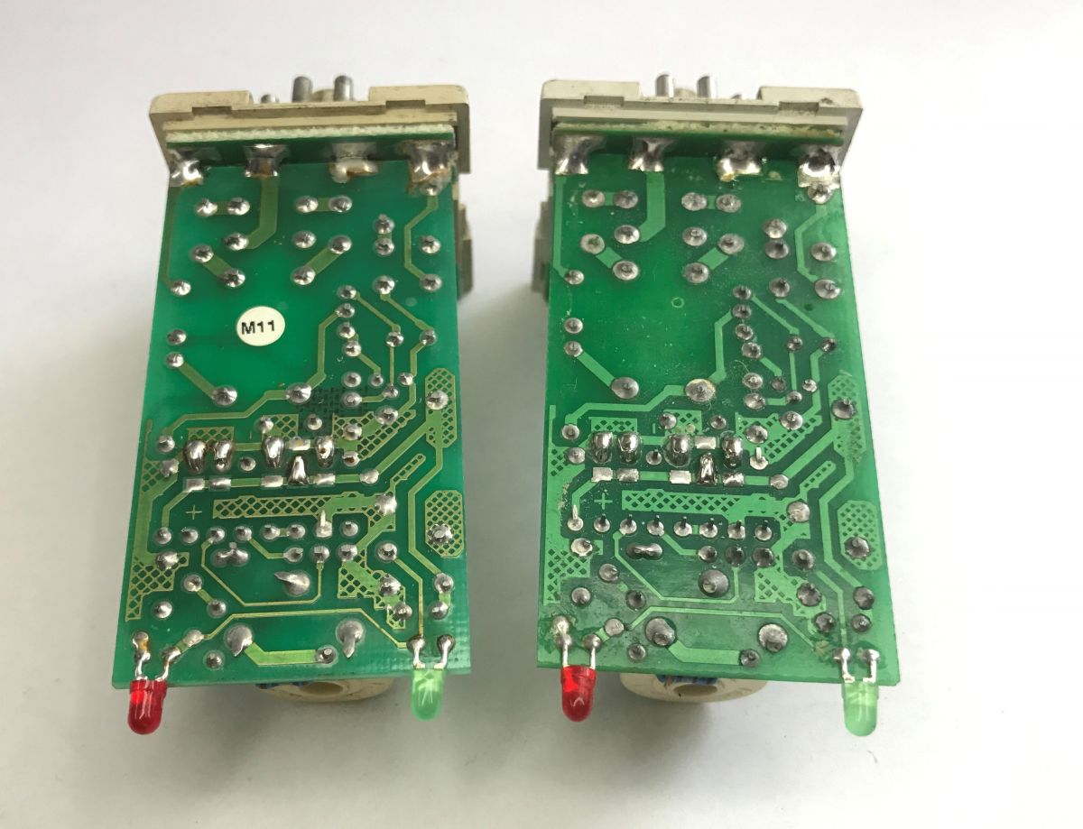
I haven’t been able to find its datasheet; it looks as though it’s some sort of chip for internal use. It has already been mentioned on our forum:
Modifying the settings of the RTx-133 timer: time adjustment and readout
Schematic of a 230V adjustable timer switch for the RM-84 relay
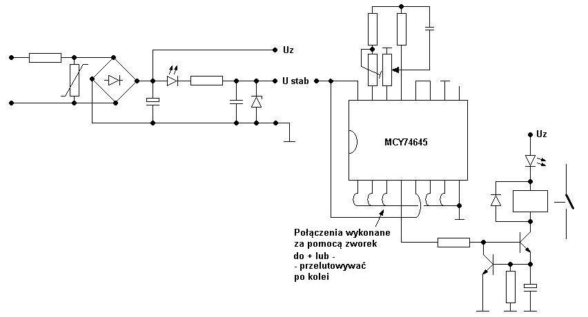
MCY 74645 in the Alstom RTX 132 relay – configuration and adjustment of operating time
I wanted to take a closer look at the components, so I desoldered the capacitor (220 uF 25V):
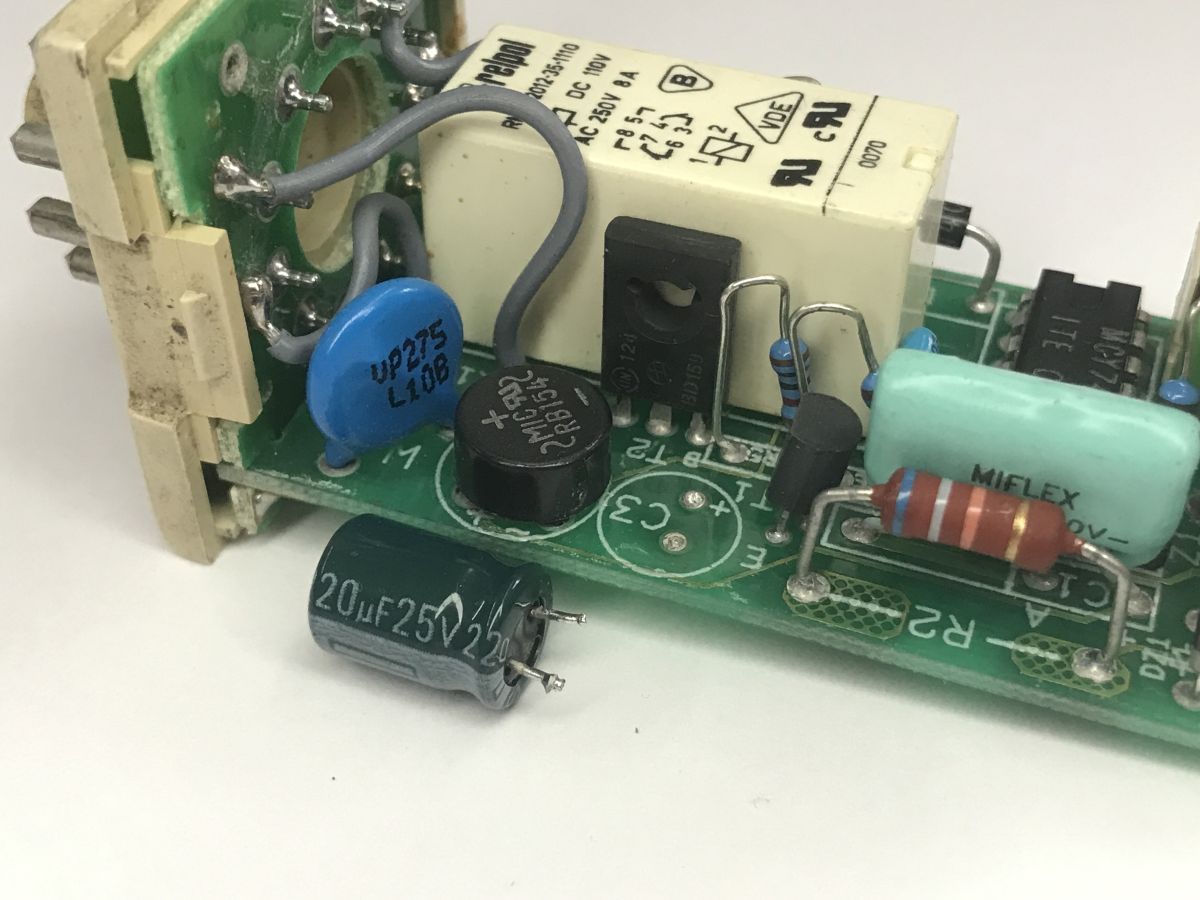
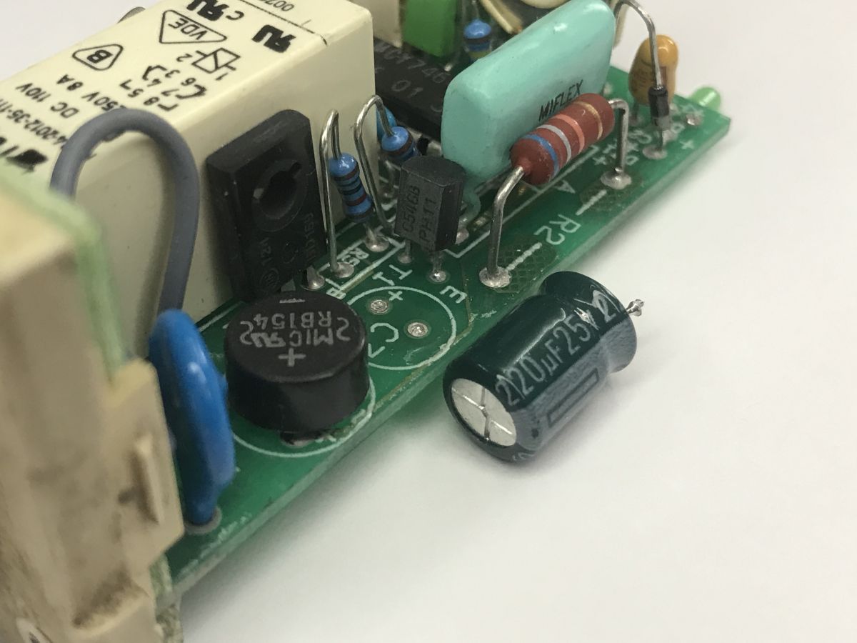
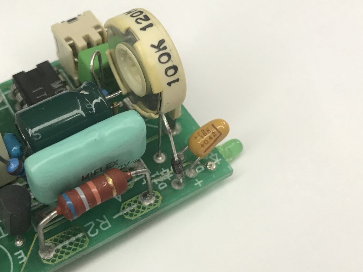
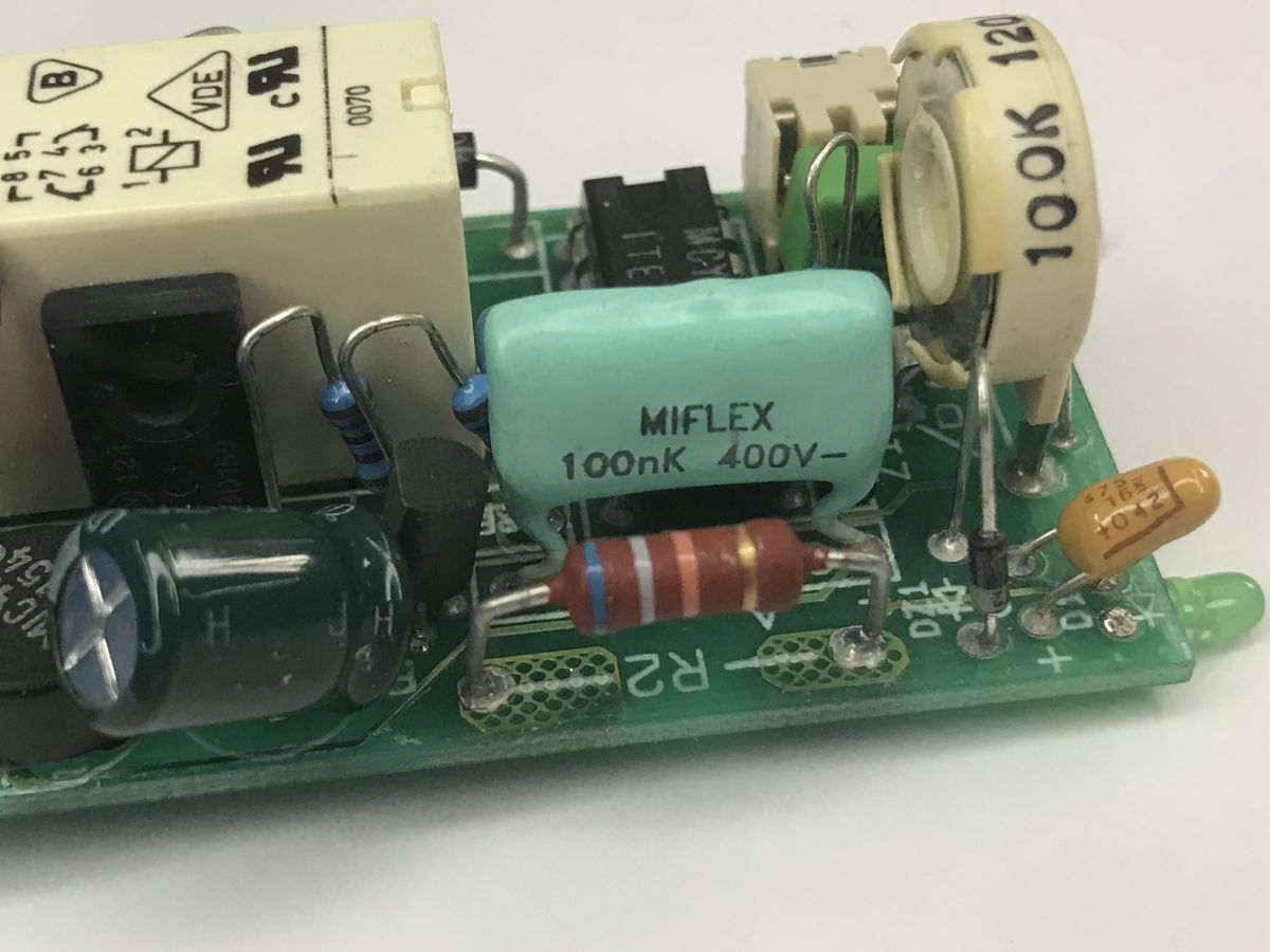
So there are two transistors there – a BC546B and a BD159. Presumably one is used to drive the other. The relay used, meanwhile, is a Relpol RM84-2012-35-1110 (Made in Poland). You can also see a varistor – for surge protection.
To sum up, although compact, the device does the job. It’s a shame there’s so little information available about the MCY74645. I wonder what the failure rate is for this type of time relay – have you had any experience with this or similar solutions, and how would you rate their longevity?

p.kaczmarek2 wrote 14827 posts with
rating 13009 , helped 659 times.
Been with us since 2014 year.
Comments
At last, a Polish integrated circuit from ‘recent’ production. According to the ITE website, they were still manufacturing it as recently as 2012. Does anyone know if they’re still mass-producing anything... [Read more]
In the 2012 report I found a reference to this chip: https://obrazki.elektroda.pl/3616966200_1783581013_thumb.jpg I wonder why anyone would make an ASIC when a microcontroller would suffice here.... [Read more]
We still have these relays in the company’s older machines. Unfortunately, the availability of new ones at ‘reasonable’ prices is very limited; they usually cost between 600 and 700 zł. Its equivalent... [Read more]
They’re cheaper. https://sklep.mikrobest.pl/pl/c/przekazniki-czasowe/11/2 [Read more]
I’ve got a few of these timer relays, some of which are unused and I’d like to sell. They’re very robust, though the potentiometer knob’s latch did have a tendency to break. [Read more]
In the end, I came to an agreement with the owner of the website http://retrokolekcja.pl/ and sent him two MCY74645 relays free of charge. Some farewell photos: https://obrazki.elektroda.pl/8147544800_1784623985_thumb.jpg... [Read more]
There is a data sheet for the 74645 chip without the letters ‘MCY’; I’ll ignore the letters ‘LS’, but that’s a completely different integrated circuit. https://obrazki.elektroda.pl/2863935800_17847... [Read more]
And what does Wiki have to say on this subject? https://obrazki.elektroda.pl/7216838300_1784705512_thumb.jpg I’ve probably managed to preserve the predecessor of this relay. https://obrazki.elektroda.pl/1192120900_1784705848_thumb.jpg... [Read more]
There is absolutely no indication that this is the chip in question. The description of the 74645 given here bears no relation to the MCY74645 and its application in this time relay. [Read more]
If you’re looking for something similar amongst TTL devices, the MCY74645 is closer to the 74123 than to the 74645 ;) At least functionally, it serves a similar purpose. [Read more]
I am well aware of that. That is why I posted a screenshot of the data sheet for the ‘standard’ 74LN645 chip, which, apart from having the same part number, has nothing in common with the MCY74546 chip. ... [Read more]