






[Thermal imaging] Internal view and test of the YSDS-60-5 4.5 A 22.5 W 5 V DIN rail power supply
TL;DR
- The Sunny YSDS-60-5 is a DIN-rail 5 V, 4.5 A, 22.5 W power supply opened for internal inspection and thermal imaging testing.
- Inside, it uses a single-sided PCB with a large heatsink, input filtering, fuse, varistor, Y capacitor, optocoupler feedback, and an OB5269 flyback controller.
- The unit delivered the promised 4.5 A, and after two hours at full load the highest temperature reached just under 70 °C.
- Voltage sagged slightly near maximum load, and the hottest parts were the Schottky rectifier and output electrolytics, raising lifespan concerns.
AI summary based on the discussion. May contain errors.
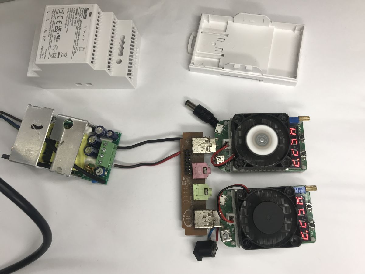
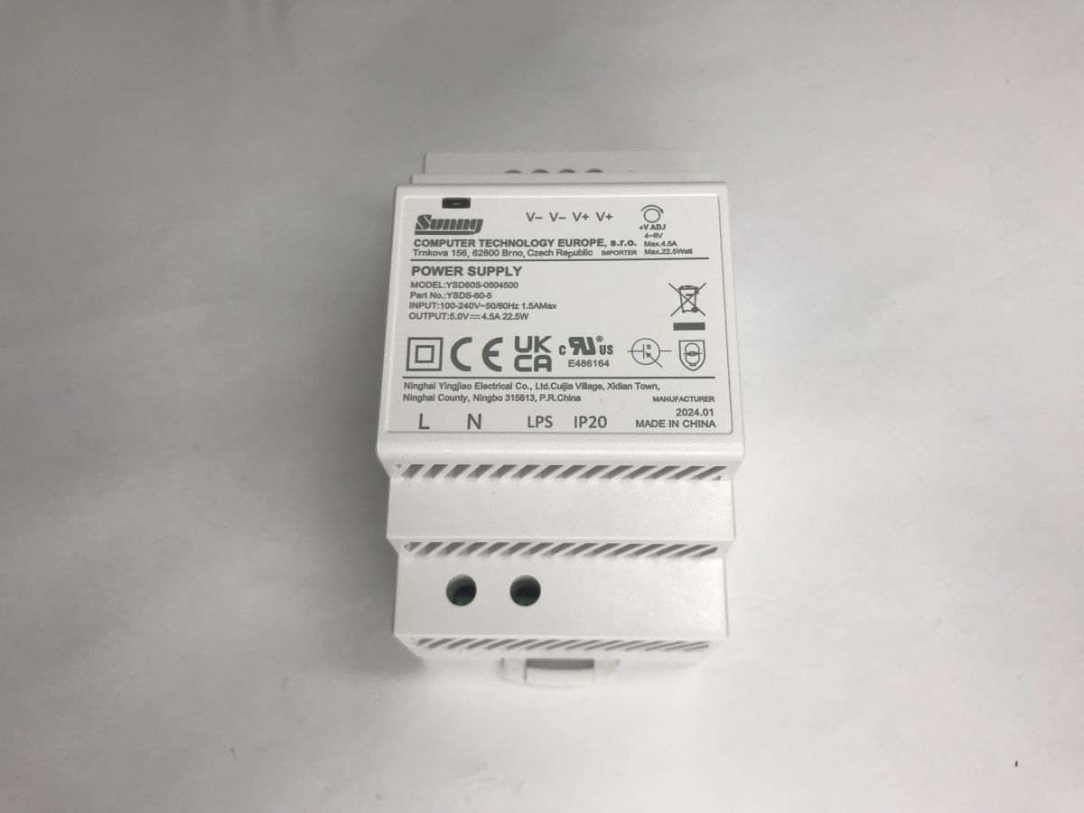
Join me for a look inside and a practical test, including a thermal imaging analysis, of the Sunny YSDS-60-5 power supply, designed for DIN-rail mounting. The unit supplies 5 VDC at a maximum current output of 4.5 A and a power output of 22.5 W, operating with an input voltage of 90–264 VAC and a frequency of 47–63 Hz. The manufacturer specifies an efficiency exceeding 85 per cent, ripple of 80 mVp-p, a full suite of overload and overvoltage protection features, and operation at temperatures ranging from -20 to +70°C, all housed in a 52x90x58 mm enclosure with an IP20 rating.
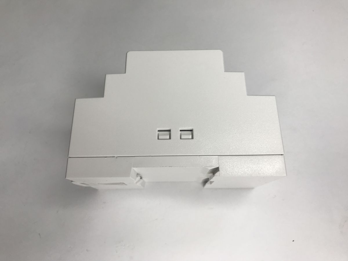
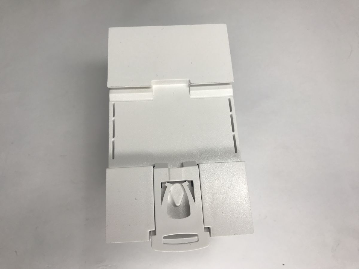
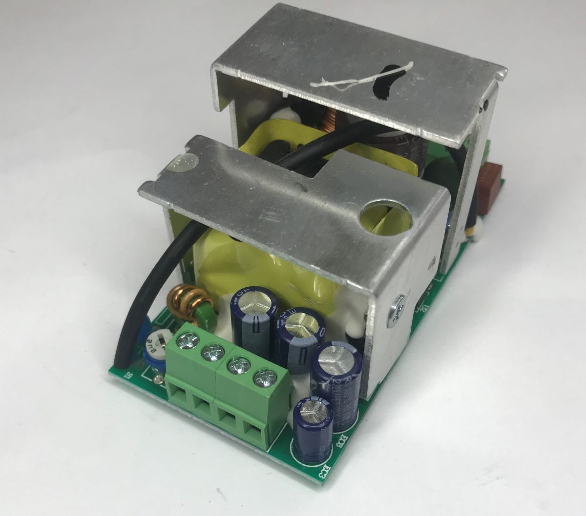
The casing is held in place by clips. You don’t even need to unscrew any screws. Inside, we can see a design based on a single-sided circuit board and a large heat sink.
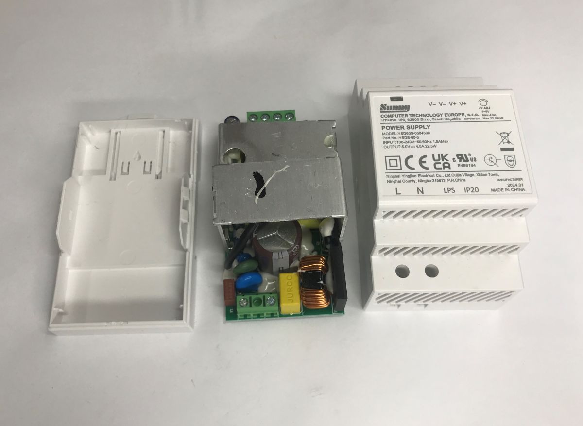
A preliminary visual inspection confirms the presence of the promised components and safety features. There are input filters, a fuse, a varistor and a Y-class capacitor connecting the primary and secondary sides; at the output, next to the capacitor bank, there is a choke.
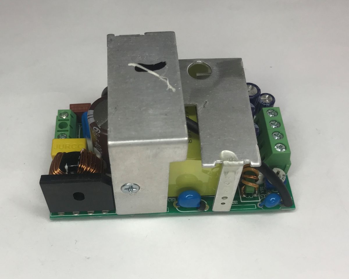
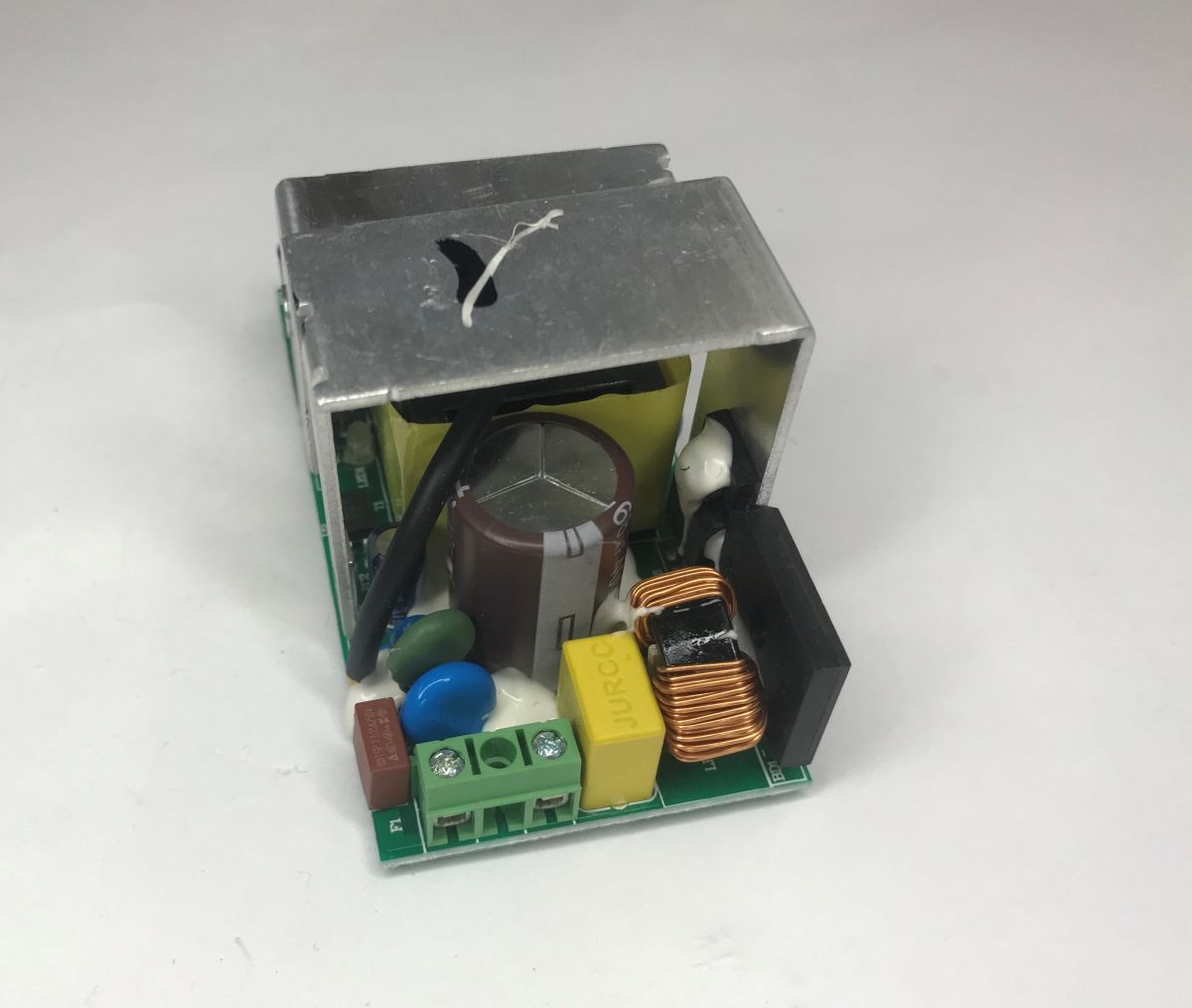
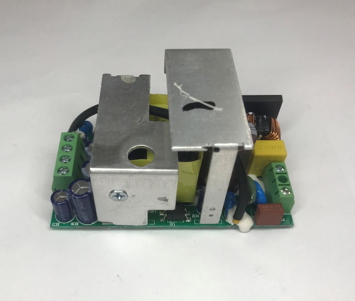
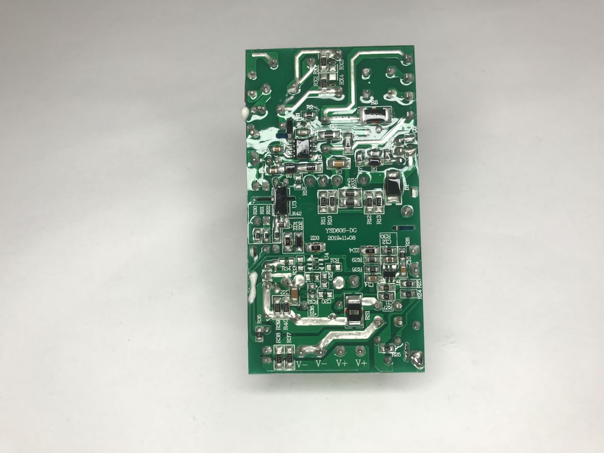
The underside of the PCB is protected by a layer of varnish:
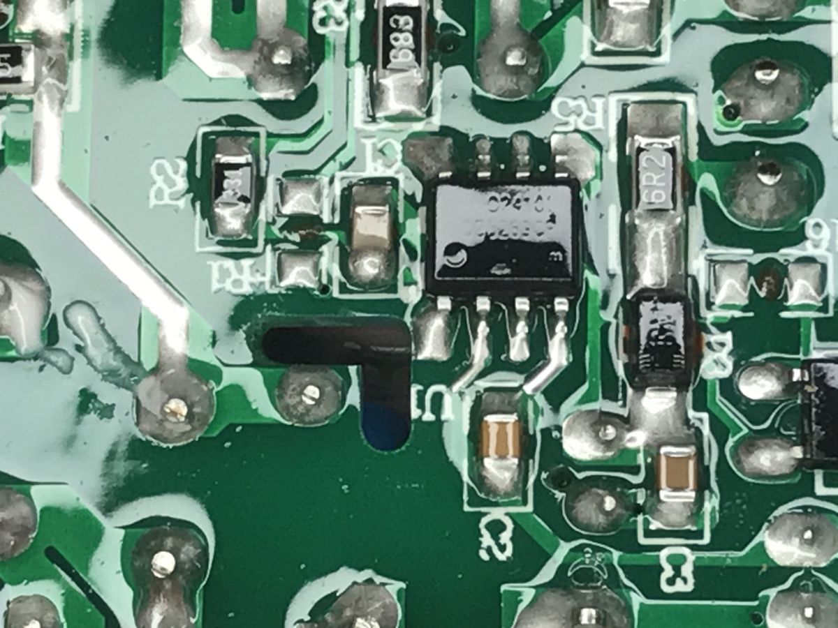
Despite this, I managed to make out the converter controller’s designation – it appears to be an OB5269.
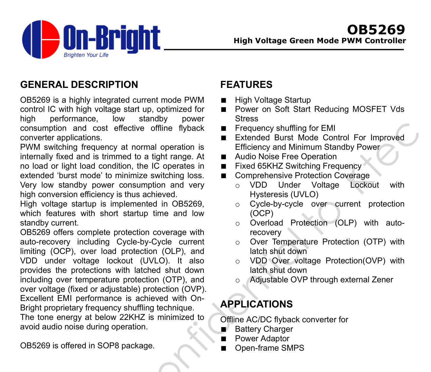
According to the data sheet, the OB5269 is a PWM controller with a built-in high-voltage start-up circuit. It features a fixed operating frequency of 65 kHz, low EMI and very low no-load current consumption (thanks to Burst Mode). It also features a full suite of protection circuits: from thermal (OTP) and overcurrent (OCP) protection to overvoltage (OVP) protection.
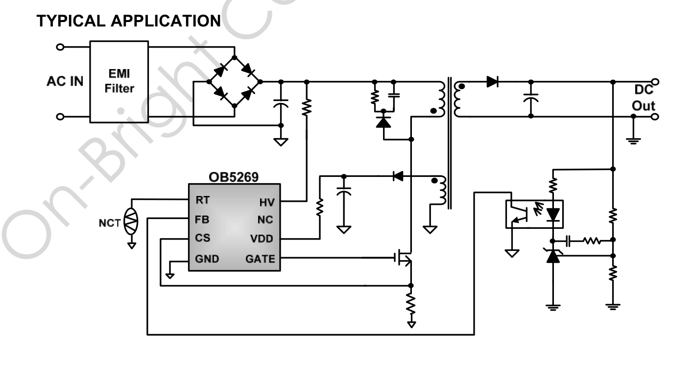
A glance at the data sheet immediately reveals a typical application circuit. This is a classic flyback topology with an external switching transistor. The chip features an integrated start-up circuit powered from the HV pin. Feedback is implemented in the simplest, traditional way – it is based on an optocoupler and, most likely, a TL431 on the secondary side. A cheap, tried-and-tested and widely used configuration.
I then moved on to practical testing. The voltage can be adjusted slightly using a potentiometer within a range of approximately 5 V. The power supply manages to deliver the promised 4.5 A, although the voltage drops slightly as it approaches this limit. Once 4.5 A is exceeded, the voltage drops slightly faster; the power supply limits the power but does not cut off the output immediately.
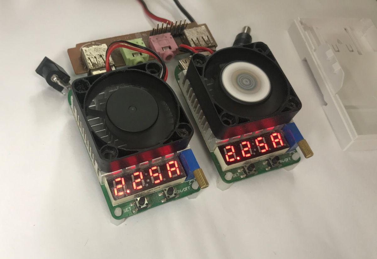
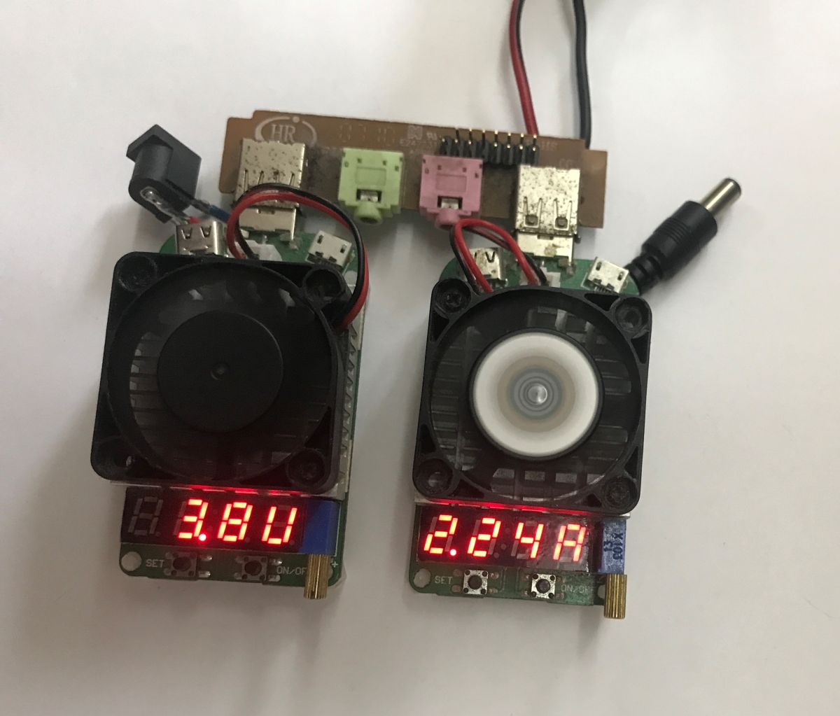
I loaded the power supply with a current of 4.5 A for 2 hours and immediately noticed that the voltage dropped slightly after a while – probably due to heating. After two hours, I checked the temperatures.
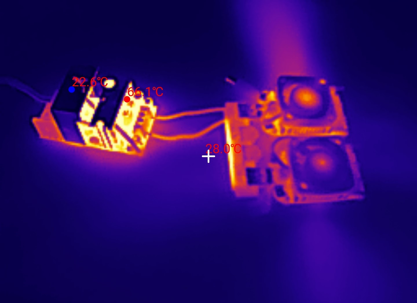
The Schottky rectifier diode at the output gets the hottest. Unfortunately, the electrolytic capacitors inevitably heat up as well. I wonder to what extent this shortens their lifespan?
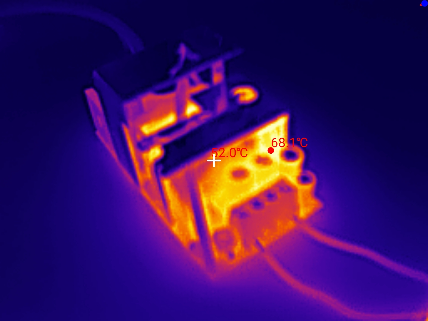
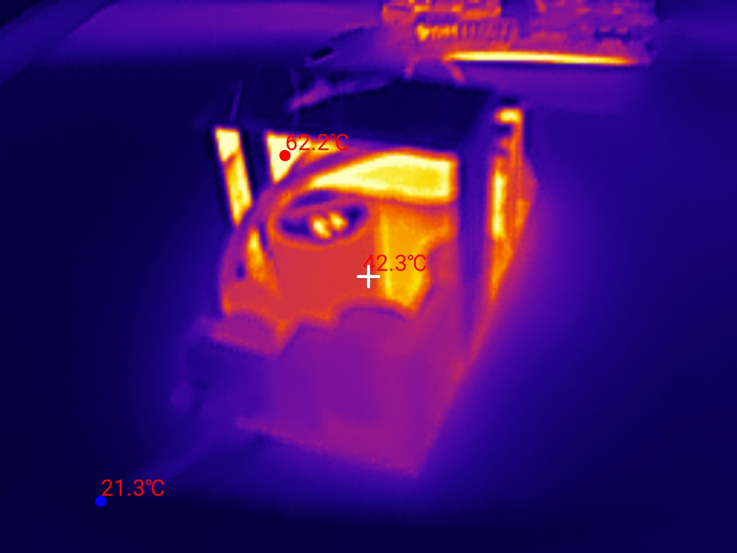
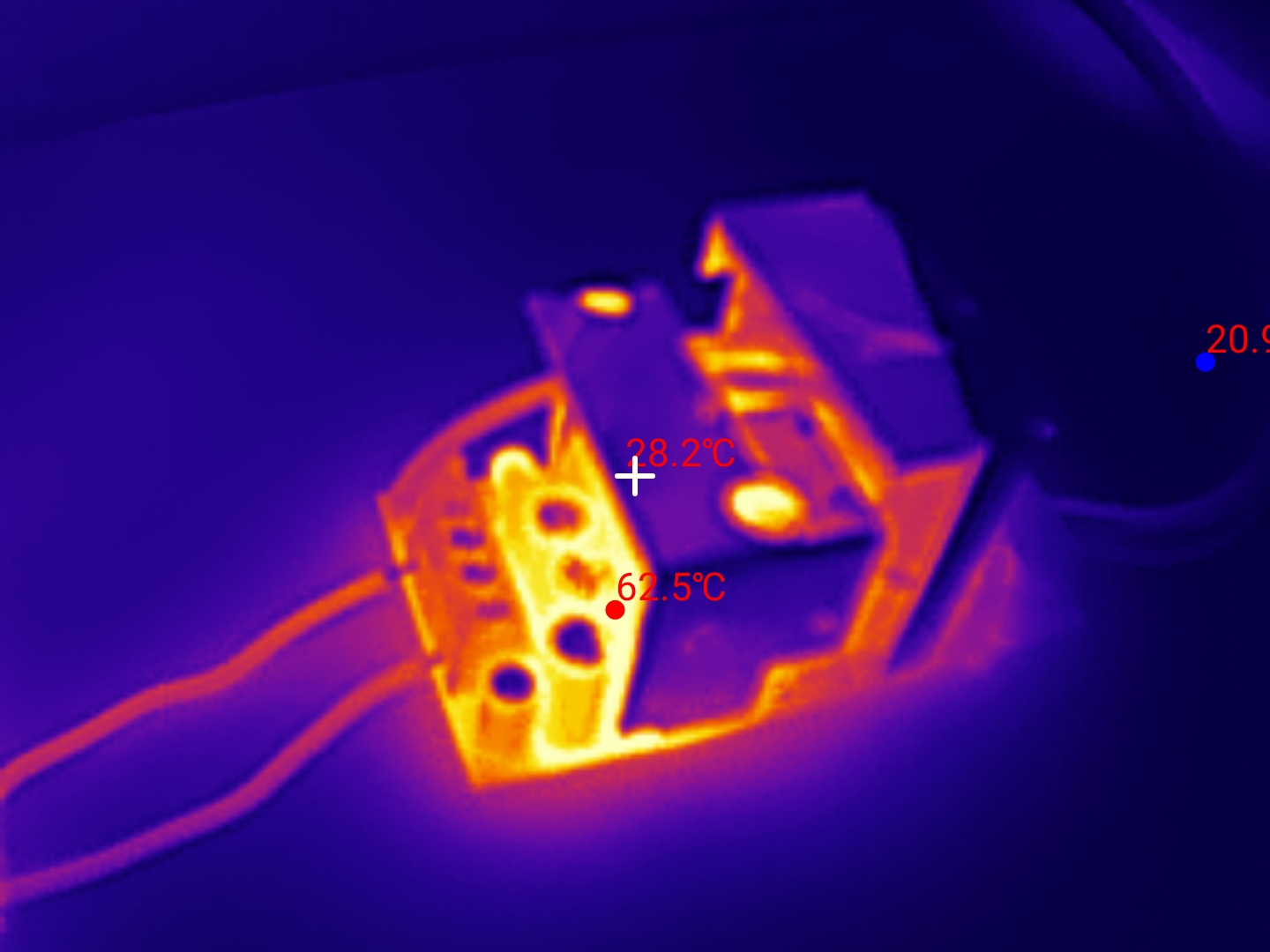
In addition, the shunt resistor heats up, which, I assume, is used for current limiting.
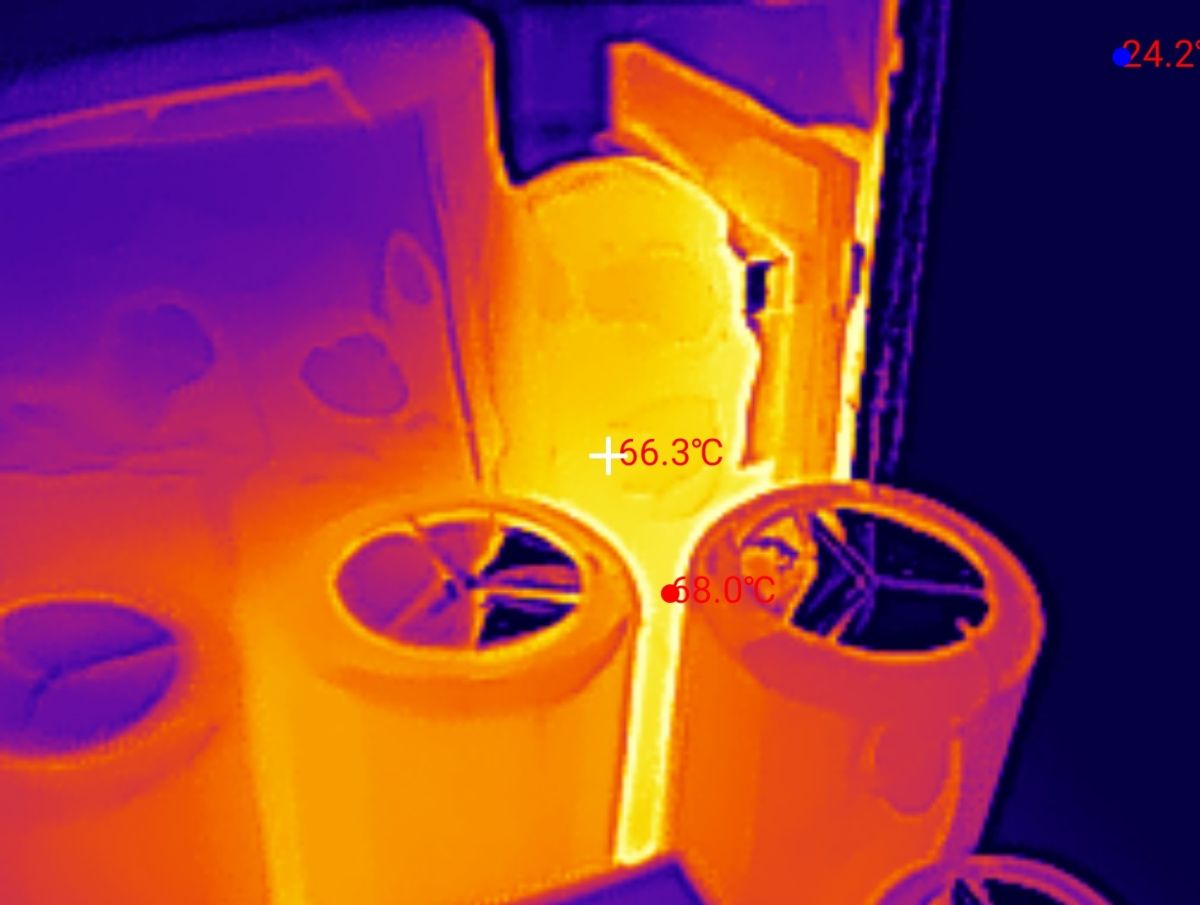
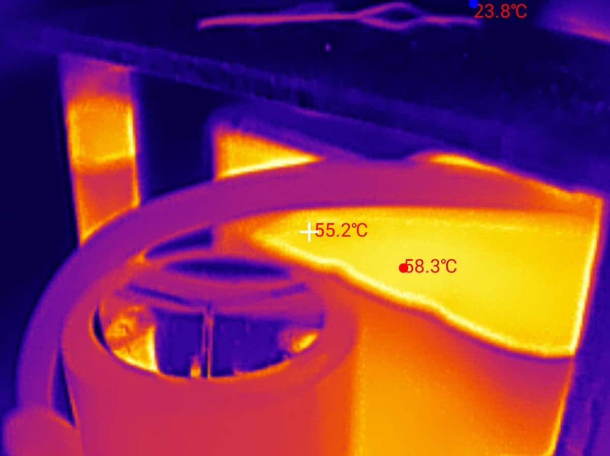
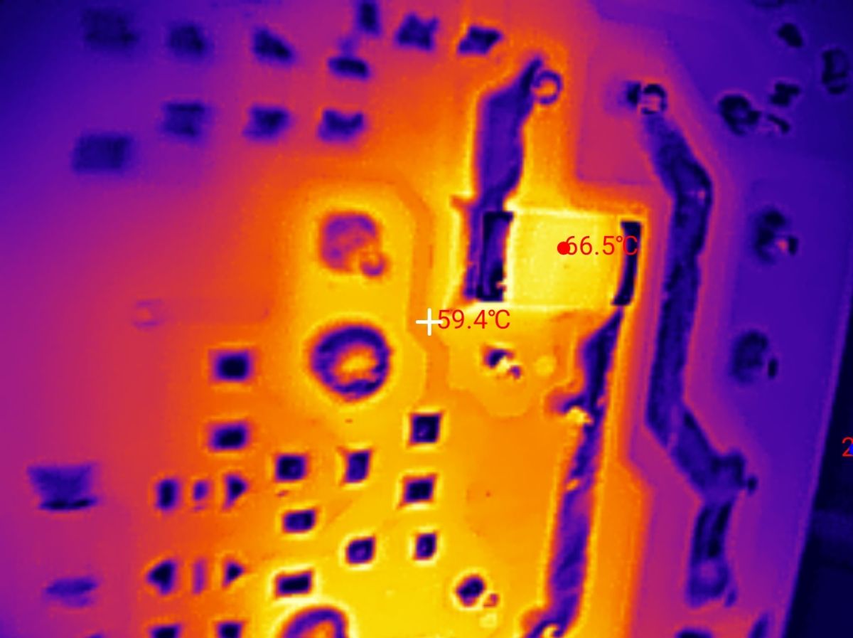
The highest temperature recorded was just under 70 °C.
To sum up, the power supply seems to deliver what the seller promised, although I am concerned about how long those electrolytic capacitors at the output will maintain their performance. There are indeed filters inside, and it also features protection against overheating and overload. I haven’t tested the ripple, though at the moment I believe this power supply will work well for my purposes, especially as I won’t be running it at full load but will leave a margin of around 1 A. It’s also worth noting the housing, which provides poor cooling in a cramped setup, but this is rather hard to avoid with passive solutions. Of course, apart from the housing, a DIN-rail power supply like this is no different from a standard power supply.
Do you use DIN-rail power supplies, and what factors do you consider when choosing them?

p.kaczmarek2 wrote 14725 posts with
rating 12810 , helped 659 times.
Been with us since 2014 year.
Comments
This is how I see it. - The insulation looks fine, and the spacing on the PCB is correct. I wonder about the insulation and construction of the transformer. Is it safe? - The capacitors are of good quality.... [Read more]