





Inside the Sicher OCH-C 275/40 surge arrester: what lies within this three-phase protection device
TL;DR
- Rozbiórka trójfazowego ogranicznika przepięć Sicher Electric OCH-C 275/40 ujawnia, jak modułowe wkładki chronią instalację przed przepięciami piorunowymi i łączeniowymi.
- Wymienne wkładki zawierają masywny warystor MOV, który po przekroczeniu progu napięcia gwałtownie zmniejsza rezystancję i odprowadza przepięcie do przewodu PEN.
- Model OCH-C 275/40 ma Uc = 275 V AC, In = 20 kA, Imax = 40 kA oraz poziom ochrony Up ≤ 1300 V.
- Mechaniczny odłącznik termiczny wykorzystuje niskotopliwe lutowie i sprężynę, aby po przegrzaniu warystora rozłączyć obwód oraz pokazać czerwony wskaźnik „IF RED REPLACE”.
- Wewnątrz wkładki znajdują się dwa prostokątne bloki warystorów, prawdopodobnie połączone równolegle dla większej wytrzymałości prądowej.
AI summary based on the discussion. May contain errors.
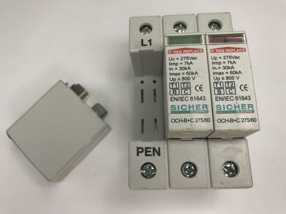
Today, something completely different – a few photos of the inside of a Class B+C surge arrester (protector). The focus of this post is the three-phase OCH-B+C 275/60 model from Sicher Electric. Its main function is to protect low-voltage installations against the effects of partial, direct and indirect lightning strikes. According to the markings on the housing, this device has a continuous operating voltage of Uc = 275 V AC, a rated discharge current of In = 30 kA and a maximum current of Imax = 60 kA. Voltage protection level Up up to ≤ 800 V.
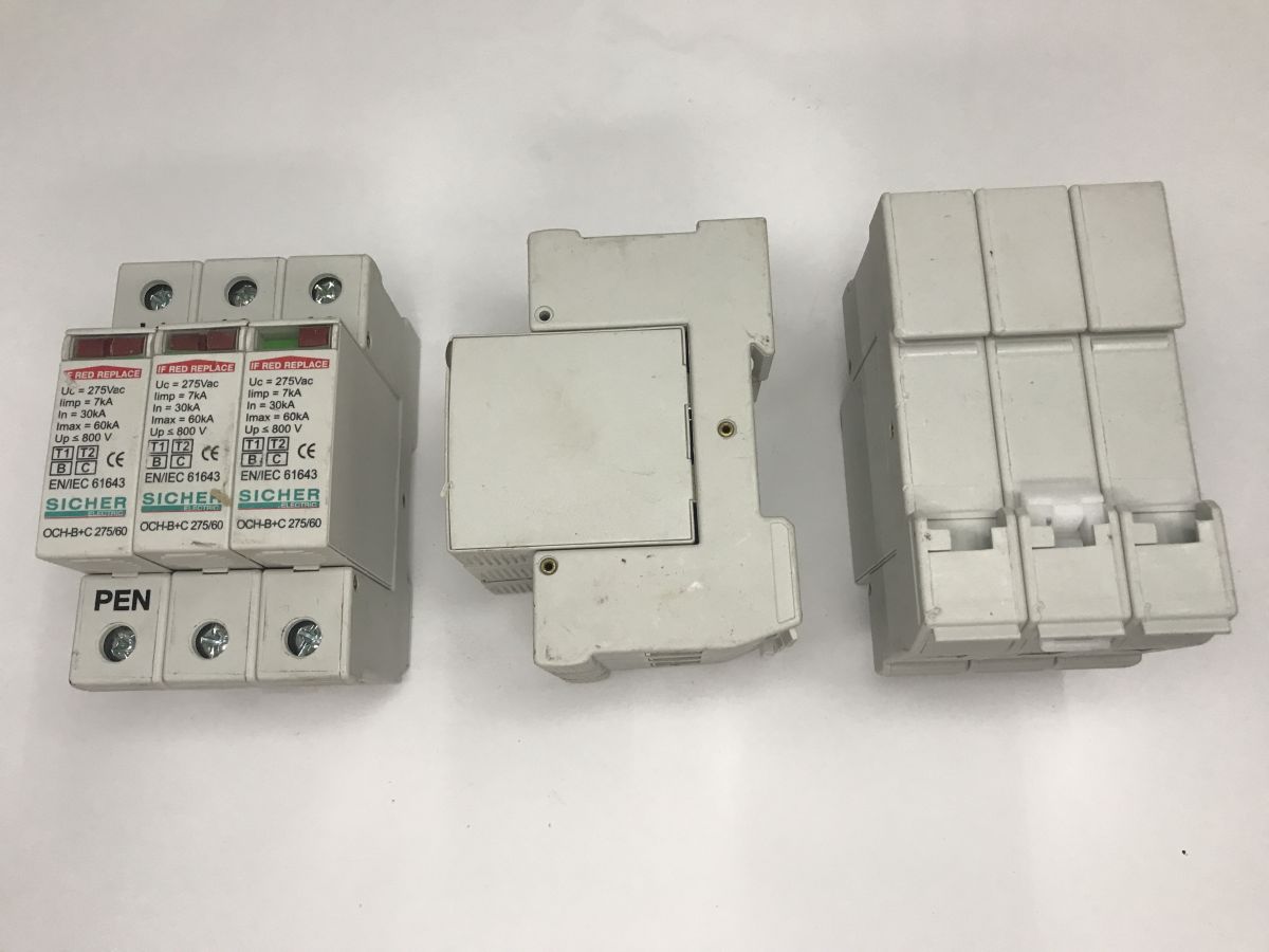
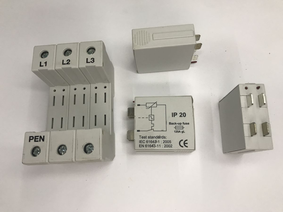
The first thing that catches the eye is the device’s modular design. There is a separate base mounted on a TH35 rail, to which the phase conductors (L1, L2, L3) and the neutral conductor (in this case, the PEN) are screwed, as well as replaceable plug-in operating inserts. This means that, once a protective element has worn out, there is no need to unscrew the cables; you simply replace the insert itself. The inserts have an IP20 protection rating.
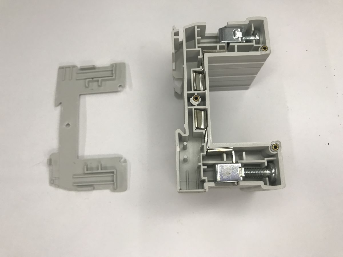
Just for the sake of it, I also had a look inside this frame, but of course, there’s essentially nothing there apart from the robust and solid contacts, which ensure good connection.
The situation is more interesting inside the cartridge. It is here that the actual surge-suppression component is hidden, namely a massive metal-oxide varistor (MOV). Its function is to instantly reduce its resistance when the mains voltage exceeds a safe threshold, and to short-circuit any dangerous surge to the PEN conductor.
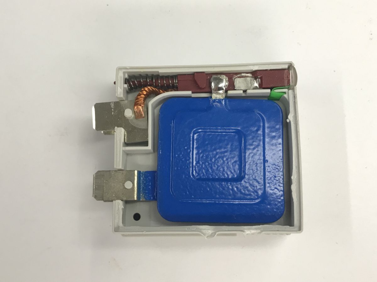
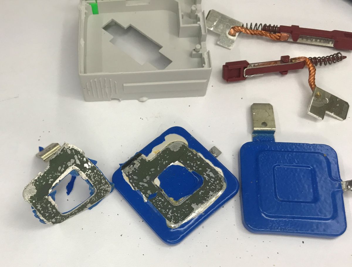
You can also see a spring-loaded mechanism which, following degradation and overheating of the varistor, releases the lock and changes the indicator to red (the inscription ‘IF RED REPLACE’). This is known as a thermal cut-out. Varistors degrade over time and with successive surges, resulting in increased leakage current and significant heating. To prevent a fire, the varistor’s terminals are soldered using a special low-melting-point solder. When the temperature exceeds a critical point, the tin melts and the visible spring mechanically pushes away and disconnects the circuit, whilst simultaneously extending a red flag onto the front panel.
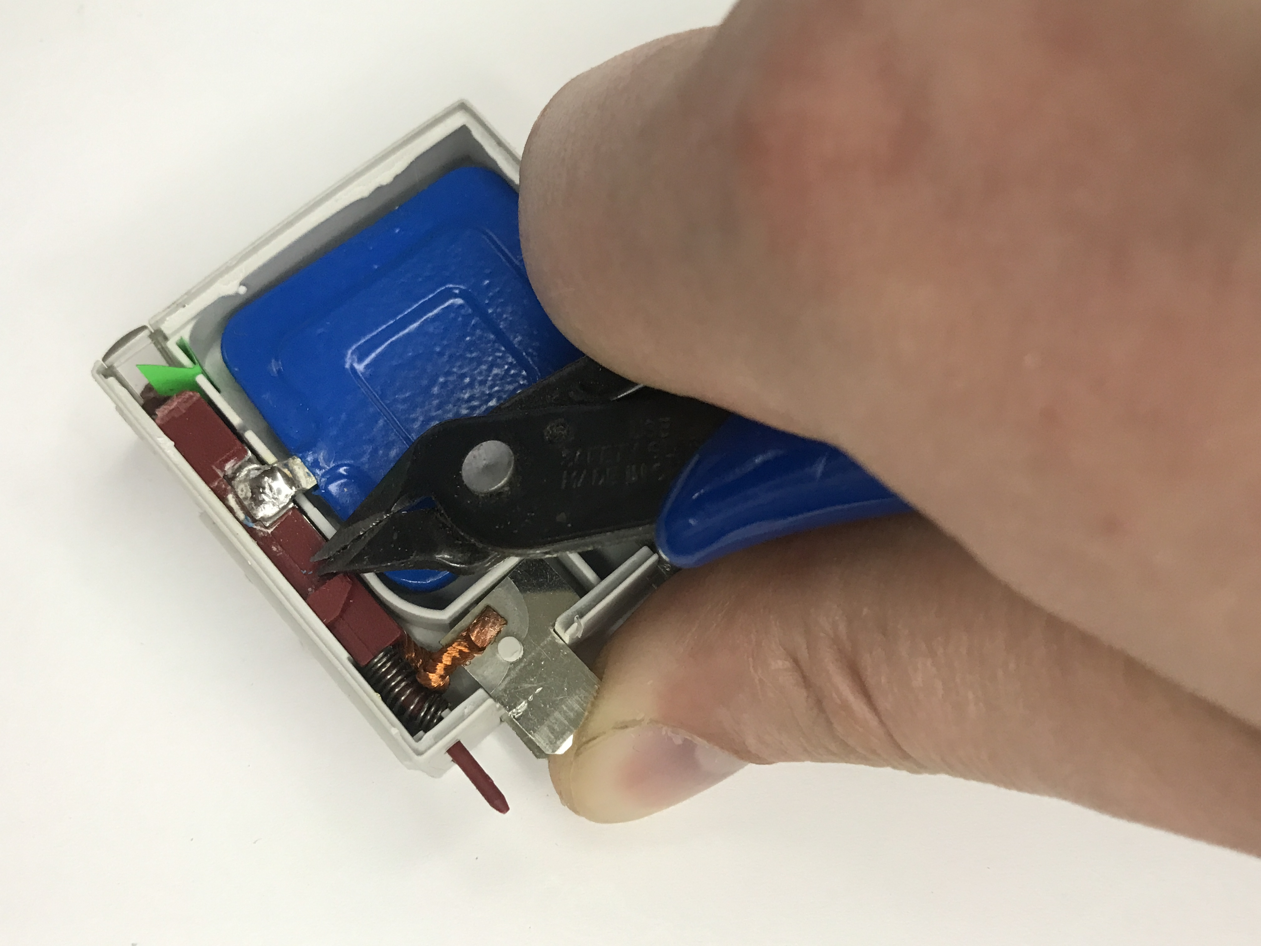
A short video demonstration – how the spring works:
After removing the cartridge:
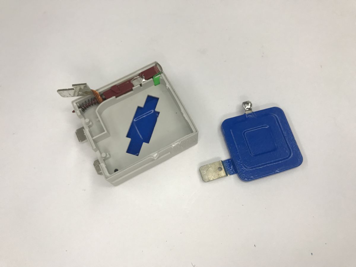
Inside, there are two rectangular varistor blocks and the clearly visible thermal cut-out mechanism with a spring, as mentioned above.
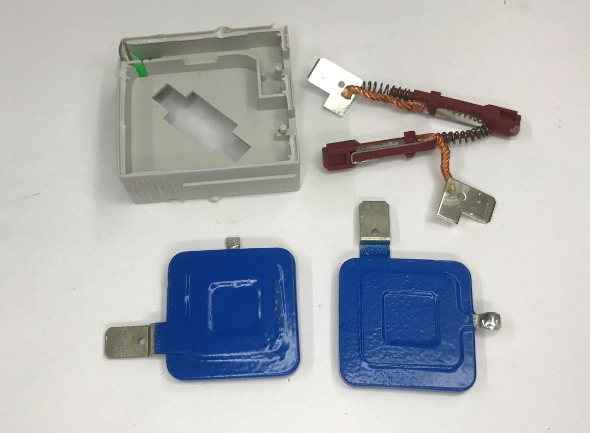
That’s basically it; I’m unlikely to be able to get inside the varistor itself…
To sum up, this was equipment completely outside my field – I tend to operate in the digital realm: functions, bytes, instructions, or perhaps TTL and CMOS levels, whereas here we have something that looks to me like a powerful, purely analogue and downright brutal energy sink. It’s a device that sits passively day in, day out, ready to short-circuit huge currents in an instant and save our electronics from destruction.
How do you rate the performance of this type of protection? What are its advantages and disadvantages?

p.kaczmarek2 wrote 14762 posts with
rating 12892 , helped 659 times.
Been with us since 2014 year.
Comments
Assuming slight wear and tear on the varistors and an increase in their leakage current, how would this affect the electricity meter’s readings? [Read more]