logo elektroda
logo elektroda
X
logo elektroda

Understanding Rising & Falling Edges in Driver Programming: S5 & S7, Diagrams & Examples

silwex 44901 13
ADVERTISEMENT
Treść została przetłumaczona polish » english Zobacz oryginalną wersję tematu
  • #1 5860504
    silwex
    Level 10  
    Please explain to me what is going on with the rising and falling edges in driver programming, especially in S5 and S7. I have already searched half of the internet and found a few topics on this subject, but I still don't understand it. Could someone, please, give me some drawings or runs to make me clear on this matter? I know these are the basics of the basics, but I decided to ask about it on the electrode anyway.
  • ADVERTISEMENT
  • ADVERTISEMENT
  • #3 5860614
    *paweł*

    Automation specialist
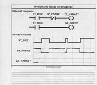
    Maybe this will brighten you up a bit. Basic step7 course Understanding Rising & Falling Edges in Driver Programming: S5 & S7, Diagrams & Examples
    Understanding Rising & Falling Edges in Driver Programming: S5 & S7, Diagrams & Examples
  • #4 5862023
    silwex
    Level 10  
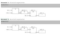
    Or maybe otherwise. Shown below are two circuits built from logic blocks in S7, in which a rising edge (Figure 1) and a falling edge (Figure 2) are realized.
    Understanding Rising & Falling Edges in Driver Programming: S5 & S7, Diagrams & Examples
    Description of the given sizes:
    E0.0; E1.0 - input signal (e.g. some disturbance)
    M50.0; M50.3 - auxiliary parameter (flank memory)
    M100.0; M103.0 - auxiliary parameter (pulse memory)
    A17.0; A17.2 - outputs
    Could someone explain to me step by step or cycle by cycle, what logical values will appear on the appropriate inputs and outputs and how should I recognize that the first system is up to the rising slope and the second to the falling slope?
  • #5 5863820
    plichta
    Level 17  
    Regarding the rising edge:
    Pressing the E0.0 button
    1 driver cycle:

    -Inquiry of inputs and markers:
    E0.0 = 1
    M100.0 = 0
    M50.0 = 0
    A17.0 = 0
    saving these states in memory before logical joining operations.

    -Logical joins, as a result of it:
    Activation of the M100.0 marker = 1
    setting M50.0 = 1
    A17.0 = 1

    - display of outputs and markers
    M100.0 = 1
    M50.0 = 1
    A17.0 = 1

    2nd cycle:
    -Inquiry of inputs and markers:
    E0.0 = 1
    M100.0 = 1
    M50.0 = 1
    A17.0 = 1

    saving these states in memory before logical joining operations.

    -Logical joins, as a result of it:

    disable M100.0 = 0
    because it works
    M50.0 = 1

    and passing this link to the output:
    M100.0 = 0
    M50.0 = 1
    A17.0 = 1

    The next cycles of the controller remain unchanged when E0.0 is activated

    Disabling E0.0 will cause the
    M50.0 = 0
    A17.0 = 0
    !!! will not change the state of M100.0 !!!!

    Conclusions: M 100.0, in the case of E0.0 operation, generates one pulse equal to 1 controller operation cycle, this pulse begins at the rising edge of E0.0. The A17.0 output is not needed here.
    The M50.0 switches off the M100.0 after one cycle


    It is similar with the falling slope.

    Added after 4 [hours] 31 [minutes]:

    Falling slope. M100.3 gives a pulse = to the controller cycle when a falling edge is detected.
    We enclose E1.0
    The first cycle of the controller:
    Polling in, out, markers (markers):
    E1.0 = 1
    M100.3 = 0
    M50.3 = 0
    A17.2 = 0
    Logical linking:
    E1.0 = 1
    M100.3 = 0 !! no reaction to the build-up !!
    M 50.3 = 1
    A 17.2 = 1
    Rewrite linking to output:
    E1.0 = 1
    M100.3 = 0
    M 50.3 = 1
    A 17.2 = 1
    End of the first cycle.

    If E1.0 = 1 is still on, then nothing happens in the next cycles. Only after releasing E1.0 the following changes occur:
    Polling in, out, tags:
    beginning of the cycle
    E1.0 = 0
    M100.3 = 0
    M 50.3 = 1
    A 17.2 = 1
    Logical linking:
    E1.0 = 0
    M100.3 = 1 !!!!!! start of the pulse
    M 50.3 = 0
    A 17.2 = 0
    Rewriting for exit:
    E1.0 = 0
    M100.3 = 1
    M 50.3 = 0
    A 17.2 = 0
    end of cycle
    Beginning of the cycle:
    query:
    E1.0 = 0
    M100.3 = 0 !!!!! end of impulse lasting 1 controller work cycle
    M50.3 = 0
    A 17.2 = 0


    To test this, the m100.3 must be connected to the setting input of the rs trigger.
    The difference between the systems is in the way of remembering the previous RLO state, the flip-flop rs is responsible for this in the case of the falling edge and sr in the case of the rising edge.
    The output A17.2 does nothing in the circuit as well as on the rising edge.
  • #6 5865476
    silwex
    Level 10  
    Thank you very much buddy 'plichta'.

    I think that if I analyze it several times, I will finally understand these activities.
  • #7 5913812
    mariuszklo
    Level 12  
    Hello

    basically the slope is a change of state from 1 to 0 (falling edge) or from 0 to 1 (rising edge). In the S7 controller there is a ready FP or FN function, in the S5 you have to do it manually. https://www.elektroda.pl/rtvforum/topic1094931.html

    Information about the change of state, i.e. about the edge, is stored on any marker and lasts only 1 program cycle, in the next it is reset to zero.
    The slope signal is often useful, e.g. if we want to turn the lamp on and off with the same button,
    if you want I can give you some examples

    greetings
  • ADVERTISEMENT
  • #8 5917228
    silwex
    Level 10  
    Yes, please provide some examples of rising and falling slopes, e.g. specifically in what practical solutions they can be used (apart from switching the lamp on and off with one button).
  • #9 5917508
    MirekCz
    Level 35  
    No imagination?

    All the moments in which you are interested in a change of state, not its current value.

    Example:
    There is a can on the conveyor belt and there is a light barrier type sensor. When the sensor detects the can, the conveyor belt is stopped, a timer is started and the liquid is poured into the can for x seconds.
    At this point, we are interested in the sensor's rising edge (informing about the appearance of the can), because from this moment we start the timer counting the time (the amount of liquid poured into the can).

    If we were not to consider the slope, but the sensor input itself, there would be problems:
    a) When the object enters the sensor and the timer starts, we cannot start it again, because the timer would never end
    b) At some point we want to start the conveyor again, but since the sensor would be set to detect the object, we would have to have some variable holding information that the can is full and we should wait for the next one.

    In short, instead of having a whole range of conditions considering all the possibilities when the sensor detects the can (start the timer, stop the feed, restart the feed), we can only have edge detection and a simple dependence that when the timer ends pouring time, the feed starts again.
  • #10 5917843
    mariuszklo
    Level 12  
    Mirek's example is good, but my imagination tells me that the S7 timers have a built-in slope mechanism and the circuit would work by connecting the input directly to the timer.

    Another example - a simple counting of items moving on a conveyor belt. We count using a photocell that gives 1 as the object is in its area and 0 when the object is not there.
    And our program could look like this:
    if photo = 1; photo is a sensor, we check the presence of the object
    if so, increase the counter by 1; the counter is the current state we have counted
    if not, go on; and that's it

    theoretically, we count items, practically there will be nonsense because the program is so fast that during the passage of one item on the tape, the program will execute e.g. 100 loops and each time it will increase the piece counter. Here the SLOPE helps, which in this case can be called the APPEARANCE of the object, thanks to which the program will get the state 1 (on the slope marker) only in one moment when the object appears in the field of view of the photo sensor and in the next program pass on the slope signal it will be 0 because the sensor has 1 all the time so the slope is gone.
    then the program:
    if appearance = 1; we check the slope
    if so, increase the counter by 1
    if not then go ahead
    makes sense and we'll calculate correctly

    often in programs where we use "latched" outputs, i.e. set, reset needs to be operated with slopes. Imagine a system built of a pneumatic actuator, a monostable control valve, the idle state of the actuator is retracted, and when we give 24V, it slides out and waits for 24V to disappear. We have end position sensors on the actuator, the actuator performs a quick, short movement.
    It is assumed that the actuator is to move when the button is pressed (the button can be released immediately), come to the end and return. It can only start when the START button is pressed again.
    kr_1, kr_2 - actuator limits
    start - START button
    st_zbocz - edge signal from START button
    q - output to the actuator valve

    if we write a program:
    And the start
    S q
    the actuator will start and will not come back, so we give:
    A kr_2
    R q
    after reaching kr_2, the actuator will start to return unless !! :
    we did not manage to release the START button - then the actuator, after leaving kr_2, will start going towards it again
    but we can get rid of it by writing:
    A kr_1
    And the start
    S q

    A kr_2
    R q
    Thanks to this, the actuator will return because in order to start it must be in the initial position, i.e. on kr_1
    only that if we still haven't released the button, the actuator will start by itself and here the slope comes to the rescue:
    A kr_1
    A st_zkocz
    S q

    A kr_2
    R q
    Thanks to this, the cycle will be performed only once and the operator must release the button and press it again to consciously start the next cycle

    -----

    the edge itself is an abstract concept, so the drivers deal with it using an additional memory cell, which stores the state of the signal of interest to us from the previous program transition.
    thanks to this, by comparing the current value and the previous value, we can state that there has been a change and save it as an edge occurrence. Then of course we rewrite the current value into memory where we keep the previous one and reread the inputs - and so on.
    in practice, we will get an impulse when the state changes at the input, I will try ascii - chart :) :

    __________ | '' '' '' '' '' '' '' '' '' '' '' 'sensor input
    __________ | '| ________ rising edge of the sensor

    another good example is the use of a slope, as in the example with an actuator, on the button that starts the machine cycle in order to eliminate the "match" operator trick - consisting of pressing the match into the starting button and going for the pipe :) - without a slope, it will work continuously, without operator supervision, on a slope it will force it to be released and re-engaged.

    greetings
  • #11 5918215
    roks
    Automation specialist
    Hello
    As for the use of the "function" for detecting a rising or falling edge - its use is as wide as PLC applications are. Every controller has it implemented in one way or another - whether in timers, registers or directly as factory functions.

    a colleague has already given the method of slope detection based on basic operations *Paul* here as a development, i.e. step by step in LD or if you prefer siemens LAD - ladder diagram - http://www.plcs.net.pl/index.php/en/Kurs-Programowania-Sterownik%C3%B3w-PLC /operacje-na-bitsach-wild-discovery.html " target="_blank" rel="nofollow noopener ugc" class="postlink inline" title="" > http://www.plcs.net.pl/index.php/en/Kurs-Programowania-Sterownik%C3%B3w-PLC /operacje-na-bitsach-wild-discovery.html

    regards

    PS. By understanding how edge detection works, you can avoid confusion where it is not directly visible (e.g. ROL, ROR, SHL, SHR etc.)
  • ADVERTISEMENT
  • #12 5918346
    mariuszklo
    Level 12  
    Do roks - the link probably does not work, he moved to plcs.net.pl but to the 404 page :)
    As for Paweł's entry - the first picture with the chart should be omitted because it is encumbered with an error.
    The previous state is NOT a negation of the current state, but only its mapping with a delay of one program cycle.
    greetings

Topic summary

The discussion focuses on understanding rising and falling edges in driver programming, particularly in Siemens S5 and S7 controllers. Participants share resources, diagrams, and practical examples to clarify how edge detection works. Rising edges indicate a transition from 0 to 1, while falling edges indicate a transition from 1 to 0. The S7 controller has built-in functions for edge detection, whereas S5 requires manual implementation. Examples include using edge detection for counting items on a conveyor belt and controlling timers based on sensor inputs. The importance of edge detection in avoiding issues with state changes in PLC applications is emphasized, along with the use of logical operations to manage input states effectively.
Summary generated by the language model.
ADVERTISEMENT