How to measure voltage with a meter?
This type of question is often asked in the forum. Therefore, I will try to explain how to measure voltages in a computer power supply so that the readings are the most accurate, and the measurement itself is safe for us.
1. Preparation of the necessary equipment for measurement.
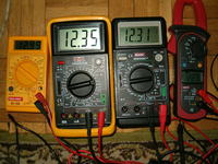
Personally, I will use the UNI-T M890G meter.
BATTERY - if our meter is powered by a battery, we should make sure that it is charged and fully functional - this will avoid measurement errors.
MEASUREMENT RANGE - the next step is to set the appropriate measuring range - in this case, set it to DCV 20 (direct current voltage, range up to 20V).

MEASUREMENT PROBES - whether our reading will be accurate also depends on the cleanliness of the measuring probes. Make sure that there is no deposit, grease or other types of dirt on them. It is best to degrease the probes beforehand, e.g. with alcohol or acetone.
If everything is ready, we can move on to point 2.
2. Performing the measurement.
We find a MOLEX plug (we use it to connect, among others, drives, hard drives, etc.)
+ 5V
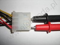
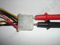
We put the probes in the same way as in the attached photo - the black probe to the place where the black wire is located and the red probe is to be found in the red wire. We read the measurement.
+ 12V
The probes are inserted as follows: black to the black wire, and red to the yellow wire. We read the measurement.
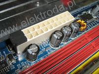
20/24 PIN socket:
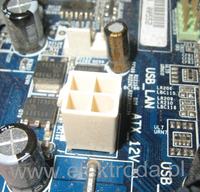
4 PIN socket:
+ 3.3V
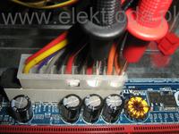
In the 20/24 PIN plug we have to find two wires - orange and black.
We put the red probe to the contact of the orange wire, and the black probe - to the black one (as shown in the pictures). We read the measurement.
+ 12V
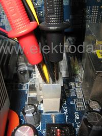
We find the 4 PIN socket. Put the red probe to the contact point of the yellow wire, and the black probe to the black contact. We read the measurement.
+ 5V SB, also marked as +5 VCCH
We perform in two states:
1. When plugging the power adapter into the mains, but the computer is not yet running.
2. After turning on the computer with the POWER button and starting all components of the computer.
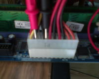
Place the multimeter (meter) probes as shown in the picture below, i.e. the red probe placed in the place of the plug marked with color purple and the black one applied to any color-coded pin black .
The voltage is very important as it allows the PC to boot properly.
In addition, in some boards there is a voltage that also supplies USB ports, so its stability and value largely depend on the correct operation of each device connected to this port.
The difference between the state 1 , that is, connecting the power supply to the network, and the state of 2 . that is, an already running computer should be the same and should not change significantly during operation.
The measured value must be within +/- 5% of the nominal voltage value, i.e. (4.75-5.25) V
+ 5V PG also marked as Power Good or Power_OK
It is the necessary voltage for the proper operation of the power supply connected to the motherboard during normal use.
In the event that this voltage is insufficient or very unstable and exceeds the values contained in the ATX standard, stable operation on the computer will be impossible. This will be manifested by turning off the power supply, incorrect startup of the computer or resetting the system.
We perform it immediately after turning on the computer with the POWER button.
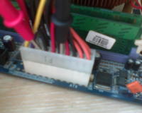
Place the red probe in the ATX plug in the pin marked with the color gray , be light green and the black probe should be placed in any pin marked with a color black like in the picture below:
The measured value must be within +/- 5% of the nominal voltage value, i.e. (4.75-5.25) V.
3. What should the correct voltages look like?
The table below shows what the tensions should look like on individual lines:

4. Finally ...
Finally, I would like to add that we measure the voltages with the computer turned on. It is best to measure 2 times:
while the computer is idle - that is, we turn off all applications and then we measure.
while the computer is under load - that is, we turn on demanding applications, e.g. GAMES, Orthos (computer-intensive application; it works on max 2 cores, so if your processor has more of them - use two parallel running Orthos, select the appropriate cores for each of the programs and then test).
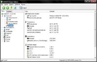
And why do we measure voltages with a meter and not programmatically?
The answer is there HERE.
Thanks to a friend spruce for help in developing and implementing the thread.
---
Prohibition of copying without the consent of the author.
This type of question is often asked in the forum. Therefore, I will try to explain how to measure voltages in a computer power supply so that the readings are the most accurate, and the measurement itself is safe for us.
1. Preparation of the necessary equipment for measurement.
Personally, I will use the UNI-T M890G meter.
BATTERY - if our meter is powered by a battery, we should make sure that it is charged and fully functional - this will avoid measurement errors.
MEASUREMENT RANGE - the next step is to set the appropriate measuring range - in this case, set it to DCV 20 (direct current voltage, range up to 20V).

MEASUREMENT PROBES - whether our reading will be accurate also depends on the cleanliness of the measuring probes. Make sure that there is no deposit, grease or other types of dirt on them. It is best to degrease the probes beforehand, e.g. with alcohol or acetone.
If everything is ready, we can move on to point 2.
2. Performing the measurement.
Voltage measurement on + 12V and + 5V lines with a MOLEX plug.
We find a MOLEX plug (we use it to connect, among others, drives, hard drives, etc.)
+ 5V
We put the probes in the same way as in the attached photo - the black probe to the place where the black wire is located and the red probe is to be found in the red wire. We read the measurement.

+ 12V
The probes are inserted as follows: black to the black wire, and red to the yellow wire. We read the measurement.

Voltage measurement on the + 3.3V, + 5V and + 12V lines using a 20/24 PIN plug and a 4 PIN plug.
20/24 PIN socket:

4 PIN socket:

+ 3.3V
In the 20/24 PIN plug we have to find two wires - orange and black.
We put the red probe to the contact of the orange wire, and the black probe - to the black one (as shown in the pictures). We read the measurement.

+ 12V
We find the 4 PIN socket. Put the red probe to the contact point of the yellow wire, and the black probe to the black contact. We read the measurement.

+ 5V SB, also marked as +5 VCCH
We perform in two states:
1. When plugging the power adapter into the mains, but the computer is not yet running.
2. After turning on the computer with the POWER button and starting all components of the computer.
Place the multimeter (meter) probes as shown in the picture below, i.e. the red probe placed in the place of the plug marked with color purple and the black one applied to any color-coded pin black .

The voltage is very important as it allows the PC to boot properly.
In addition, in some boards there is a voltage that also supplies USB ports, so its stability and value largely depend on the correct operation of each device connected to this port.
The difference between the state 1 , that is, connecting the power supply to the network, and the state of 2 . that is, an already running computer should be the same and should not change significantly during operation.
The measured value must be within +/- 5% of the nominal voltage value, i.e. (4.75-5.25) V
+ 5V PG also marked as Power Good or Power_OK
It is the necessary voltage for the proper operation of the power supply connected to the motherboard during normal use.
In the event that this voltage is insufficient or very unstable and exceeds the values contained in the ATX standard, stable operation on the computer will be impossible. This will be manifested by turning off the power supply, incorrect startup of the computer or resetting the system.
We perform it immediately after turning on the computer with the POWER button.
Place the red probe in the ATX plug in the pin marked with the color gray , be light green and the black probe should be placed in any pin marked with a color black like in the picture below:

The measured value must be within +/- 5% of the nominal voltage value, i.e. (4.75-5.25) V.
3. What should the correct voltages look like?
The table below shows what the tensions should look like on individual lines:

4. Finally ...
Finally, I would like to add that we measure the voltages with the computer turned on. It is best to measure 2 times:
while the computer is idle - that is, we turn off all applications and then we measure.
while the computer is under load - that is, we turn on demanding applications, e.g. GAMES, Orthos (computer-intensive application; it works on max 2 cores, so if your processor has more of them - use two parallel running Orthos, select the appropriate cores for each of the programs and then test).
And why do we measure voltages with a meter and not programmatically?
The answer is there HERE.
Thanks to a friend spruce for help in developing and implementing the thread.
---
Prohibition of copying without the consent of the author.


