logo elektroda
logo elektroda
X
logo elektroda

Custom 6mm Sheet Metal Buffer Heat Accumulator for 30KW Wood-Fired Boiler in Basement

xrafaladam 60516 39
ADVERTISEMENT
Treść została przetłumaczona polish » english Zobacz oryginalną wersję tematu
  • #1 7893008
    xrafaladam
    Level 11  
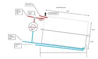
    Due to the costs of factory-made devices for heat accumulation, and the problem with bringing in a ready-made device, I am thinking of having such a buffer welded out of 6mm sheet metal. I am limited by the width of the cellar door of 80 cm, so I decided to make two elements with dimensions of 2 x 1 x 0.78 m collar, turn in the basement and put on some stand. I don't need any coils at the moment, everything will go together. The boiler is wood-fired 30KW, open system. The house is tiny so there is a large excess of boiler power in relation to the demand. I only burn wood.

    I am wondering about the problem of the proximity of the inlet pipe from the furnace to the outlet to the heat receivers, i.e. so that the water does not go from the furnace and is immediately sucked into the heat receivers. Water will be pumped from the boiler by a pump, similarly as from the buffer to the heat receivers. How to solve it? As for the returns, I will lead the pipes through the entire buffer so that the stove sucks in water from the lowest point, and it will be similar back from the heat receivers. (access to the buffer will be only on the left side of the image)

    I will leave a few stubs at different heights so that in the future you can add some more devices, and of course some sockets for thermometers, etc.

    I also wonder if it makes sense to paint the buffer from the inside, if so, with what. I heard an opinion that after some time the paint will be garbage in the installation and the walls will still be covered with limescale.

    Another problem is the connection of both elements, how to seal it so that it does not leak.

    Thermal insulation is planned with mineral wool, but I do not know what is best to put on top of the insulation.

    I saw that some buffers use funnels inside, which is supposed to be related to better water circulation. I plan to give some reinforcements so that the buffer does not deform.

    I will be grateful for any suggestions and comments regarding my project.
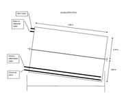
    Custom 6mm Sheet Metal Buffer Heat Accumulator for 30KW Wood-Fired Boiler in Basement
  • ADVERTISEMENT
  • #2 7893662
    adam0369
    Level 11  
    An interesting idea to store heat, but the very idea of storage is associated with losses, but this colleague probably counts. As for my suggestions: the tank can be welded from a thinner sheet (e.g. 2 mm) and galvanized or, as a colleague suggests, from 6 mm sheet and left black. As for the structure inside, I would not finish the furnace return pipes and receivers at the same height, and I would even put a partition between them at the same power supply. Sealing compound can be used to seal the flange (it is purchased in the form of silicone and applied to the joints before screwing). It is mandatory to insulate well, you can use wool but polyurethane foam is better, after complete assembly, wrap the buffer with a thin galvanized sheet, leaving around 5 - 8 cm of space and fill it thoroughly with foam. You should also consider disconnecting the stove from the buffer when the stove is no longer burning so that it does not become a receiver, a solenoid valve on the return and a thermostat that would turn off the pump at the stove would be enough. That's all my suggestions, cheers
  • #3 7896615
    wawrzeczko_t
    Heating systems specialist
    Galvanized elements are not used in central heating installations

    I suggest not to combine only if you do - connect 2 or 3 smaller buffer tanks in parallel (a 300 l buffer has a diameter of about 75 cm). The advantages are: warranty, checked tightness, original insulation, coat, etc ... www.elektromet.pl www.pomex.pl
  • #4 7898758
    mroziuu
    Level 12  
    Does it make more sense to use such buffers connected to what without any coils? Are there any tables, converters or something that could be used in the decision?
  • #5 7899528
    wawrzeczko_t
    Heating systems specialist
    I don't know if it makes sense. It depends on the whole plumbing scheme of your house.
  • #6 7900302
    xrafaladam
    Level 11  
    I have open installations at home, it works by gravity, but there is also a pump. Copper pipes fi 20 on risers and fi 15 for radiators. There are about 220 liters in the installation, including a large share of the stove and boiler jacket. Cast iron radiators. Domestic water from a 120 liter boiler with a jacket. The top of the overflow vessel will be approx
    6 meters above the bottom of the buffer.
    As for the buffer, maybe I will actually add a coil for hot water under the "ceiling" of the buffer and maybe a second one at the floor for solar, because if I twist it and insulate it, it will be a pity to open it again, especially since the lid can weigh 300 - 400 kg.

    So far I've imagined it something like this:


    Custom 6mm Sheet Metal Buffer Heat Accumulator for 30KW Wood-Fired Boiler in Basement
  • #7 7902891
    xuzi
    Level 13  
    I recommend especially

    http://forum....

    Moderated By mirrzo:

    I have removed the inactive link

  • #8 7913190
    xrafaladam
    Level 11  
    The address of this page has changed because they had some reorganization of the page in Murator, but in fact the topic of the buffer is described there exhaustively.
    Thanks for the info.
  • ADVERTISEMENT
  • #10 8596638
    krzysztof64
    Level 11  
    Please judge whether a 60-litre "toddler" made of an air cylinder from a truck, placed in a 1000-litre "mother" heated to about 65 - 70 degrees Celsius is enough to take a bath in a bathtub?
  • #11 9186153
    wnoto
    Level 34  
    wawrzeczko_t wrote:
    Galvanized elements are not used in central heating installations

    I suggest not to combine only if you do - connect 2 or 3 smaller buffer tanks in parallel (a 300 l buffer has a diameter of about 75 cm). The advantages are: warranty, checked tightness, original insulation, coat, etc ... www.elektromet.pl www.pomex.pl


    But such a 300 l tank is PLN 1,500. By betting 2-3 items, we have almost PLN 5,000.
    In my opinion, it's expensive and that's why many people think about self-made.
  • ADVERTISEMENT
  • #12 10639322
    xrafaladam
    Level 11  
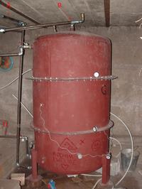
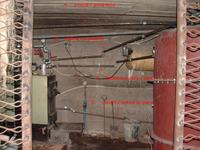
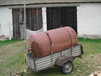
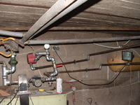
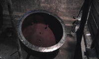
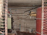
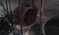
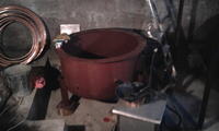
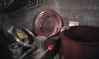
    Coming back to the topic from two years ago, instead of welding a square in the basement, I decided to buy a 1700 liter scrap tank. I had a good welder cut it into 3 pieces and weld the legs and flanges. I also showed where to weld what muffs. I did the rest myself :) )
    It's not fully functional yet, but it's working.

    Custom 6mm Sheet Metal Buffer Heat Accumulator for 30KW Wood-Fired Boiler in Basement Custom 6mm Sheet Metal Buffer Heat Accumulator for 30KW Wood-Fired Boiler in Basement Custom 6mm Sheet Metal Buffer Heat Accumulator for 30KW Wood-Fired Boiler in Basement Custom 6mm Sheet Metal Buffer Heat Accumulator for 30KW Wood-Fired Boiler in Basement Custom 6mm Sheet Metal Buffer Heat Accumulator for 30KW Wood-Fired Boiler in Basement Custom 6mm Sheet Metal Buffer Heat Accumulator for 30KW Wood-Fired Boiler in Basement Custom 6mm Sheet Metal Buffer Heat Accumulator for 30KW Wood-Fired Boiler in Basement Custom 6mm Sheet Metal Buffer Heat Accumulator for 30KW Wood-Fired Boiler in Basement Custom 6mm Sheet Metal Buffer Heat Accumulator for 30KW Wood-Fired Boiler in Basement Custom 6mm Sheet Metal Buffer Heat Accumulator for 30KW Wood-Fired Boiler in Basement

    there are no photos after thermal insulation and I don't have a decent automatic control yet, but I already know that the buffer is a bull's eye :) )
    I wonder how many days in the summer I will have enough hot water after lighting the fire once.
  • #13 10639762
    mirrzo

    VIP Meritorious for electroda.pl
    Quite a hodgepodge. And it works?
  • #14 10639941
    xrafaladam
    Level 11  
    Of course he works
    has not yet reached full functionality because it does not yet have a decent control and is tinkering with automatic valve actuators. For now, it controls the valves manually, but everything works as it should. :) )
  • #15 10640024
    mirrzo

    VIP Meritorious for electroda.pl
    xrafaladam wrote:
    Custom 6mm Sheet Metal Buffer Heat Accumulator for 30KW Wood-Fired Boiler in Basement


    xrafaladam wrote:
    Of course ... everything works as it should. :) )

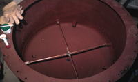
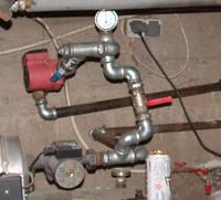
    I wonder how you bleed the system this node with the red pump. What are these PEXs coming out of the buffer for? What is this cross made of copper pipes at the bottom of the tank for?
  • #16 10640157
    xrafaladam
    Level 11  
    From the red pump, the system is vented at the radiators, i.e. from the pump, the air flows gravitationally to one of the radiator vents.

    As for the pexes from the buffer, they lead hot water from the upper coil of the buffer to taps, washbasins, etc., the pex connects to the pex leading from the boiler, which is the source of hot water before the buffer started. Because the whole project is an experiment for me, I left the boiler as a reserve DHW tank, working by gravity with the furnace (for a rainy day, i.e. buffer failure or long-term power failure)

    The crosses at the bottom of the tank (also at the top) are the frame of the coils. It is known that copper elements cannot be in direct contact with steel elements (electrolytic corrosion or something similar), so I screwed the copper frame, of course, through rubber washers to carry the weight of the coils.

    The link given above by "mroziuu" leads to an extremely extensive thread on the murator forum about heat buffers, the topic has already hundreds of pages, so it is difficult to quickly get information from it. About a year and a half ago I read the whole thing and I have to say that I implemented a lot of things given on this forum when building my buffer.
  • #17 10640179
    mirrzo

    VIP Meritorious for electroda.pl
    xrafaladam wrote:
    From the red pump, the system is vented at the radiators, i.e. from the pump, the air flows gravitationally to one of the radiator vents.

    That is, part on the pump, and the rest on the radiators :( In open systems, there is a constant probability of air bubbles forming, so the pump can run with air in it. You should rework it so that everything self-vents, above the pump.

    xrafaladam wrote:
    ....so I screwed the copper frame, of course, through rubber washers to carry the weight of the coils.

    And you insulated the bolts too, and the water too? Will these crosses bear the coil without bending and resting on the bottom? check after a season or two.
  • #18 10640252
    xrafaladam
    Level 11  
    I think you misunderstood me with the vent. Going from the pump, there is a gravitational path of air bubbles to the installations where there is an automatic air vent at each radiator. So everything above the pump is self-bleeding.

    As for the screws holding the copper crosses, I put a layer of silicone on the screws (where they could touch the copper elements sideways).

    As for "isolating the water", I understand that it is a mockery. I do not know the exact name of the undesirable phenomenon, but I am sure that direct contact between copper and steel elements in such systems should not be allowed. So this kind of foresight is probably not a mistake. If not, I'd appreciate you letting me know.

    The mechanical strength of the crosses seems to me sufficient, and as for the control, the problem is to check anything inside the tank, unless I find a gooseneck camera and let it through one of the holes. The mountain itself weighs about 150kg-200kg. So I hope I won't have to open it soon.
  • #19 10640704
    mirrzo

    VIP Meritorious for electroda.pl
    xrafaladam wrote:
    Coming from the pump is gravity...

    How about the pump?
    xrafaladam wrote:
    As for the screws holding the copper crosses, I put a layer of silicone on the screws ...

    Plastic hoses would be better
    xrafaladam wrote:
    So I hope I won't have to open it soon.

    You should provide for an inspection window, because over time, a lot of stuff accumulates at the bottom of the hopper
  • #20 10641325
    xrafaladam
    Level 11  
    mirrzo wrote:
    xrafaladam wrote:
    Coming from the pump is gravity...

    How about the pump?
    xrafaladam wrote:
    As for the screws holding the copper crosses, I put a layer of silicone on the screws ...

    Plastic hoses would be better
    xrafaladam wrote:
    So I hope I won't have to open it soon.

    You should provide for an inspection window, because over time, a lot of stuff accumulates at the bottom of the hopper


    The pump is vented the other way, i.e. at the top of the buffer, there is one automatic vent and one manual vent, ultimately pulled out on PEX beyond the insulation.

    I can manage without the inspection window. I don't think it will be that bad. As a last resort, I will take a day's time, ask someone for help and remove the top cover. After all, if I managed to put it on, I can take it off and then I can even go inside with the welder.

    And as for the plastic hoses, the ones used by NASA would be even better, but I couldn't find a link to their online store :) )
  • #21 10643924
    1tropek
    Level 23  
    xrafaladam wrote:
    And as for the plastic hoses, the ones used by NASA would be even better, but I couldn't find a link to their online store :) )

    FROM


    Cool.
    Unnecessary malice towards the person trying to help you.

    The whole structure amazes me.
    There is an idea, there is knowledge, there is motivation, there is implementation.
    My entry is not ironic, I actually admire the contractor, the implementer of this idea.
    If I can suggest something - replace these galvanized fittings with black ones and add some inhibitor to the boiler water.
    Fingers crossed.
  • #22 10644188
    xrafaladam
    Level 11  
    I'm wondering if it's worth replacing these galvanized fittings, or boiler scale won't do the trick?
    I hope that it can last 20-30 years and then we will probably all warm ourselves with electricity or return to the caves.

    With this igielite, "mirzo" was probably right, but I think silicone will also do its job. I hope my friend wasn't offended :) )

    All in all, it was on this forum that I started the whole adventure with the buffer and so I thought that I would write what the case ended up with and it's too late for major changes. Someday you have to stop improving and start using it and it took me almost two years to do it in installments.

    Now I'm struggling with the controls and actuators closing the valves.

    The annoying thing is that the heat escapes me gravitationally from the buffer, even though I reworked the connections so that they were U-shaped, but it did not solve the problem. Then the hot water escapes to the radiators. I was wondering if it makes sense to put non-return valves behind the pumps, such as those used in drinking water, so that it does not return, but I am concerned whether it will somehow significantly reduce the efficiency of the pumps and whether there will be no problem with venting (the pump may not push the valve without water, and not until it pushes the valve to release the air). As a last resort, I will do some solution with electrically closed valves, but the return ones may solve the problem. What do you think?
  • ADVERTISEMENT
  • #23 10644805
    1tropek
    Level 23  
    xrafaladam wrote:
    The annoying thing is that the heat escapes me gravitationally from the buffer, even though I reworked the connections so that they were U-shaped, but it did not solve the problem.


    In my "idea" I used a used Vaillant three-way valve. The one with 1" connectors.
    Controlled 220V - if you supply voltage, it "releases" heat from the buffer, without voltage - closes the outlet.
    Regards.

    ps.
    As for the bottom support.
    Three plastic tubes (legs), properly cut out, distancing the lower coils.
    I didn't invent it - that's how they do it in the "factory" ones.
  • #24 10644843
    mirrzo

    VIP Meritorious for electroda.pl
    xrafaladam wrote:
    Going from the pump, there is a gravitational path of air bubbles to the installations where there is an automatic air vent at each radiator.

    xrafaladam wrote:
    The pump is vented the other way, i.e. at the top of the buffer, there is one automatic vent

    Custom 6mm Sheet Metal Buffer Heat Accumulator for 30KW Wood-Fired Boiler in Basement
    I still don't understand something here. How is it possible, since the pump and pressure gauge are the highest points in this part of the installation.
  • #25 10644872
    1tropek
    Level 23  
    mirrzo wrote:
    I still don't understand something here. How is it possible, since the pump and pressure gauge are the highest points in this part of the installation.


    Assuming for granted that the can is upright. :D :D :D

    The upper pump is in series with the lower one?
    In this configuration it "milks" the buffer.
  • #26 10645423
    xrafaladam
    Level 11  
    mirrzo wrote:
    xrafaladam wrote:
    Going from the pump, there is a gravitational path of air bubbles to the installations where there is an automatic air vent at each radiator.

    xrafaladam wrote:
    The pump is vented the other way, i.e. at the top of the buffer, there is one automatic vent

    Custom 6mm Sheet Metal Buffer Heat Accumulator for 30KW Wood-Fired Boiler in Basement
    I still don't understand something here. How is it possible, since the pump and pressure gauge are the highest points in this part of the installation.


    The photo is quite unfortunate, this is a thermometer clipped on a tube. Above this place, everything spreads by gravity to the installation. (behind this insulated pipe you can see a thicker black one)

    As for connecting the pumps, the connection visible in the picture should ultimately be closed. If the buffer valves are opened and closed, the installation returns to the state it was in before the buffer was connected.
    The original idea was that the black pump pumped only to the buffer, while the red pump from the buffer to the radiators. The connection shown in the picture between them should be closed. But now I think it would be a bit of a waste, because when the stove was burning and wanted to heat the house at the same time, two pumps would run together unnecessarily. Ultimately, I want to give a 3-way valve behind the black pump and then the controller would decide whether to release heat from the black pump to the house or to the buffer. The red pump would turn on only when the furnace is not on fire and you would like to run hot water from the buffer to the radiators.

    I'll try to take better pictures tonight and draw a diagram.
  • #27 10660361
    kidu22
    Level 35  
    Typical DIY. I like the boiler exit resized to 1/2 inch. And these pumps.

    A 3-way valve and thermostatic timer control would be useful.
  • #28 10660747
    Bogdanbenek
    Level 20  
    kidu22 wrote:
    Typical DIY. I like the boiler exit reduced to 1/2 inch. And these pumps.

    A 3-way valve and thermostatic timer control would be useful.


    3\4 inch there I see or 1 inch and the pump has a half screw connection for 1 inch I don't see 1\2 inch in this photo :?:
  • #29 10670664
    xrafaladam
    Level 11  
    Custom 6mm Sheet Metal Buffer Heat Accumulator for 30KW Wood-Fired Boiler in Basement

    all connections are 1'', while the outlet from the furnace with a differential valve (gravity) is 6/4"
  • #30 16467153
    zbyszekkr
    Level 17  
    xrafaladam wrote:

    Custom 6mm Sheet Metal Buffer Heat Accumulator for 30KW Wood-Fired Boiler in Basement

    Hello.
    How did you make these beautiful collars?

Topic summary

The discussion revolves around the construction of a custom 6mm sheet metal buffer heat accumulator for a 30KW wood-fired boiler, addressing challenges related to heat storage efficiency and installation constraints. Users suggest various design considerations, including the use of thinner galvanized sheets, insulation techniques, and the importance of proper pipe connections to prevent immediate heat loss. The conversation also touches on the potential for integrating coils for hot water and solar heating, as well as the necessity of ensuring the system is self-venting to avoid air bubbles. Participants share experiences with DIY solutions, including the use of existing tanks and modifications to enhance functionality. Concerns about corrosion, insulation, and the overall plumbing scheme are also discussed, emphasizing the need for careful planning and execution in the design of the buffer system.
Summary generated by the language model.
ADVERTISEMENT