logo elektroda
logo elektroda
X
logo elektroda

Diagram of central heating and domestic hot water installations with a buffer -

seiko.36 81780 31
ADVERTISEMENT
Treść została przetłumaczona polish » english Zobacz oryginalną wersję tematu
  • #1 18078150
    seiko.36
    Level 12  
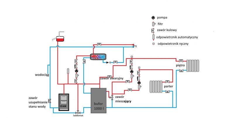
    I plan to do the installation at home myself, I drew a diagram, please give feedback and comments if something is wrong.
    The drops in the central heating installation are significant and will be as shown in the diagram.
    I plan to connect the pipes to the buffer at the same height as in the diagram.
    The valve marked as emergency will be opened in the event of a power failure during burning in the furnace or other failures.
    Diagram of central heating and domestic hot water installations with a buffer -

    I am asking for opinions and comments on this scheme.
  • ADVERTISEMENT
  • Helpful post
    #2 18078885
    andrzej lukaszewicz
    Level 41  
    What is this boiler? Connections between the boiler and the buffer should be made with thick pipes, preferably min. 5/4, or better 6/4 "with appropriate slopes, it will facilitate work in natural circulation.
    http://czysteogrzał.pl/instalacja-grzewcza/bufor-ciepla/
    I recommend the diagram according to nilsan, the last one in the given link.
  • #3 18079953
    seiko.36
    Level 12  
    The planned boiler is ATMOS DC 25S.
    The pipes will be as large as possible. I was wondering if the valves between the boiler and the buffer are a good idea?
    I do not understand the given diagram, I do not see the possibility of precise regulation of the return temperature. For me, this diagram to which the link is given in the post above is somehow overcomplicated.
  • #4 18080090
    andrzej lukaszewicz
    Level 41  
    This layout (according to nilsan, not others) just has no drawbacks of the ladomat, read the whole topic carefully.
    The temperature can be regulated very precisely, which is why there is a ZT valve, i.e. with a thermostatic head and a sensor with a capillary 9, which measures the return temperature and corrects the opening of the valve on an ongoing basis to create a mixing effect.
  • ADVERTISEMENT
  • #5 18080112
    seiko.36
    Level 12  
    What kind of mixing, like a pump, will practically suck only water from the buffer through a pipe from the bottom, and not from the power supply from above, because this is how gravity works in such an installation. It makes no sense to me.
    Can you write what are the disadvantages of a laddomat?
  • ADVERTISEMENT
  • #6 18080138
    andrzej lukaszewicz
    Level 41  
    Dude, I made 2 such circuits with this scheme and everything works perfectly.
    seiko.36 wrote:
    What kind of mixing, how the pump will suck practically only water from the buffer through a pipe from the bottom, not from the supply from above

    You are wrong, when the capillary senses that the water is too cold when returning to the boiler, it opens the ZT valve and the pump starts to work on a short circuit through the ZT valve and only partially takes the cold water from the buffer. The condition is that the valve should be min. 1 "with a large Kv.

    Added after 2 [minutes]:

    seiko.36 wrote:
    Can you write what are the disadvantages of a laddomat?

    Please read the article carefully. I sent you.
  • ADVERTISEMENT
  • #7 18080169
    seiko.36
    Level 12  
    OK, how does it work then congratulations. I will not make such a layout, if I do not use a laddomat, I will do the layout from Kalvis in this article.
    He's so much better for me.
    Subjective article, disadvantages of laddomat - apart from the price, far too high for me.
    Laddomat has the same flow, the temperature is the same, sufficiently high, so you can't smear with dry fuel.
  • #8 18081625
    seiko.36
    Level 12  
    Such a good scheme that no one else has any comments?
  • #9 18082433
    andrzej lukaszewicz
    Level 41  
    You are wise, and you don't know much ... Don't you know the difference? Then do as you see fit, it's your money and installation. The calvis system has no or very limited circulation in the event of a power failure with a hot boiler.
    The Laddomat and the Nilsan system work identically in terms of mixing and flows, otherwise how else would it work?
    During the heating up phase of the buffer in the laddomat, natural circulation occurs through the pump (although it is turned off) and heat is transferred to the extinguished or cooling boiler. In the system I am talking about, the pump is placed high on the level of the top of the boiler and we have a siphon effect and no circulation.
    In addition, you can use any pump (energy-saving electronic), not the older generation that was installed by the manufacturer and period. There is of course a version with such a pump, but the price ???
    The thermostatic insert has a constant opening temperature, and if you want to experiment with temperatures (with different opals and dew points in relation to the buffer loading speed), you have to replace and buy a new one - another cost. Here you have a smooth adjustment from 40-70 degrees on the return (I used such heads with a capillary and TS-90 herz valves with increased flow.)
    The cost of the replacement system is: pump, e.g. EPCO Leszno + flare nut 300 PLN, set TS valve + head 180 PLN, flap valve 5/4 "40 PLN, filter, shut-off valves 120 PLN, 3 thermometers + tees 60 PLN (really only one is enough for return of the boiler), additional fittings, let it be a hill from PLN 100. Total PLN 800 max. and a little more work, but it is probably less important because:
    seiko.36 wrote:
    I plan to do the installation at home myself
  • Helpful post
    #10 18082696
    Kot-huncwot
    Level 21  
    Hello.
    The IMO system is overcomplicated. Well, I have the opinion that the simpler the better.

    The furnace of the type specified by you requires a power supply. No power supply means that all pumps are stopped (including the entire Laddomat) and the furnace is stopped.

    And there is no LADDOMAT. There is a circulation pump and a three-way thermostatic mixing valve, which is simple and understandable. Some crooks have come up with a new name for the elementary set of pump + mixing valve, put it in one box and do business. Probably the largest on the included flare nuts. I am of the same opinion about the famous ball valve which is supposed to enable gravity operation in the absence of electricity, especially in floor heating systems with a decent gas boiler.

    Well, I'm not qualified to be a modern businessman.

    This system cannot work without electricity, so think about the emergency valve. I do not know to what extent the drawing corresponds to the reality, but if you have an open expansion vessel, give the boiler-vessel pipe at the tee outlet, and the outlet for the installation on the tee leg. And blow off the automatic air vent. You will have a beautiful venting through the expansion vessel.
  • #11 18082749
    seiko.36
    Level 12  
    Kot-huncwot wrote:
    This system cannot function without electricity


    Laddomat lets off when the pump is not working
    Diagram of central heating and domestic hot water installations with a buffer -

    Kot-huncwot wrote:
    You will have a beautiful venting through the expansion vessel


    And I just don't want to vent through the expansion vessel.
    The boiler is to operate at high temperatures and it is better if the air escapes through the vent than through the pipe to the expansion tank.
    I know what is happening when there is a lot of gas in such a pipe to the expansion tank, I saw the effects.
    I even want to install a tee so that the leg leading to the tank points downwards, so that under normal conditions the pipe does not get air in it.
    Diagram of central heating and domestic hot water installations with a buffer -
  • #12 18083355
    Kot-huncwot
    Level 21  
    Hello.

    I am not alpha and omega, I do not claim the right to "mania" only right and everything that I write here is IMO. I'm not in the habit of scuffling who's smarter. I deeply believe in simplifying everything possible, because this direction of thinking has been working for many years. You want a laddomat, you have a laddomat and rightly so, because that's what they recommend in the boiler manual and it is probably a warranty condition. When he lets it pass, he lets it pass. The ATMOS DC25S boiler, on the other hand, has a control board on the top and they say something about it that it gasifies and has a fan, probably with an electric drive - I found this boiler in the network especially. I do not know how such a boiler behaves in the absence of power, but probably completely different than when powered by electricity. And this is what I wanted to draw my colleague's attention to.
  • Helpful post
    #13 18083569
    hajtaler
    Level 21  
    seiko.36 wrote:
    I know what is happening when there is a lot of gas in such a pipe to the expansion tank, I saw the effects.
    [quote = "seiko.36"]
    I wonder what did you see? Sure how it throws the water out of the vessel? It throws out and with such a connection as in the diagram it will be thrown out. The vessel connection is wrong. It should be like this Diagram of central heating and domestic hot water installations with a buffer -
    Unless you've seen something else, but I can't imagine what - a properly connected vessel naturally ventilates the installation and has no negative effects

    seiko.36 wrote:
    I even want to install a tee so that the leg leading to the tank points downwards, so that under normal conditions the pipe does not get air in it.

    And this is against the regulations - the pipe to the vessel should be led ascending all the time, without siphoning. I advise you to review the standard.
    Generally, I agree with my colleague @Andrzej_;) lukaszewicz that
    andrzej lukaszewicz wrote:
    You are wise, and you don't know much ...

    and you are looking more for applause for your inventions than for advice

    Added after 8 [minutes]:

    Why do you have separate pumps for each floor at the collection? The installation is so extensive? If you do not heat a 500m villa, one pump will be enough
  • #14 18083914
    seiko.36
    Level 12  
    What have i seen Like water in a boiler, it boiled so much that it fired, and the water from the expansion tank did not run out, because the steam did not release.

    hajtaler wrote:
    And this is against the regulations - the pipe to the vessel should be led ascending all the time, without siphoning. I advise you to review the standard.

    OKAY . valuable note, it will be in accordance with the rules of course.

    hajtaler wrote:
    you are looking for applause for your inventions rather than advice

    You have a right to think so, but I'm seeking advice.
    There will be two pumps, because I do not use thermostatic heads, but room regulators on both levels.
    This is what I thought of and it will be so. Is it legal?
  • #15 18083971
    hajtaler
    Level 21  
    seiko.36 wrote:
    What have i seen Like water in a boiler, it boiled so much that it fired, and the water from the expansion tank did not run out, because the steam did not release.

    It must have been a badly connected vessel. If you connect to the vessel as in the diagram I added, and lead from the boiler as vertically as possible (preferably as in your last diagram to this vent). Then you can cook at will and nothing bad will happen. The water will not be thrown out from the vessel, but the steam will escape through the upper pipe and crash against the water level in the vessel, and excess will escape through the vessel's venting.
    seiko.36 wrote:
    This is what I thought of and it will be so. Is it legal?

    The regulations only regulate the protection of the boiler. What and how you mount it on the installation is up to you.
    seiko.36 wrote:
    There will be two pumps, because I do not use thermostatic heads, but room regulators on both levels.

    Then ok, but I don't know (I'm not sure) if you need a separate mixer for each pump
    Below you have the standard for connecting the vessel. Especially point 2.6
  • #16 18084402
    seiko.36
    Level 12  
    What about the safety tube?
    In point 2.2 it is not listed as "Basic Safety Devices" so it doesn't have to come from the boiler, I conclude.
    The diagram below is changed.
    hajtaler wrote:
    Then ok, but I don't know (I'm not sure) whether you need a separate mixer for each pump

    I plan to use a HERZ MIXING VALVE 6/4 "with a KVS 25, so I don't see a problem with blocking or anything. Each pump will get what it takes.

    Diagram of central heating and domestic hot water installations with a buffer -
  • #17 18084596
    hajtaler
    Level 21  
    seiko.36 wrote:
    What about the safety tube?
    In point 2.2 it is not listed as "Basic Safety Devices" so it doesn't have to come from the boiler, I conclude.
    The diagram below is changed.

    It is entered - 2.2b as securing tubes and in 2.6 it is specified what kind of tubes they are. The safety pipe is among them. As you have in the diagram, it may be better if it goes straight from the boiler. If you leave it like you do now, it is worth giving 90 ° bends to a longer section of 2x 45.
    This automatic air vent must not be there - with the return pump, the air vent on the suction side of the pump will draw in air
  • #18 18084810
    seiko.36
    Level 12  
    I will use 2x45 degree elbows as much as possible, good idea.

    hajtaler wrote:
    This automatic air vent must not be there - with the return pump, the air vent on the suction side of the pump will draw in air

    The regulations do not prohibit it, so it will be.
    I saw an air vent above the buffer in various diagrams, for me it will be close to the boiler with a minimum drop towards the buffer.
    The expansion tank will be 6 meters above the boiler and it is not possible to suck in air through the vent, because there will be a pressure of 0.59 bar above the stove.

    Now I will show you what is my idea for a safe connection with the expansion tank. Now you can write that I am wise :D
    It doesn't meet the rules, I know, but is it such a bad idea :?:
    In such a system, I would definitely not use an automatic air vent.


    Diagram of central heating and domestic hot water installations with a buffer -
  • #19 18084845
    hajtaler
    Level 21  
    It is not about the static pressure of the water column, but about the negative pressure - the installation with the pump on the return works under negative pressure, so it will suck, but you are right - it is not forbidden.
    Such connection of the vessel as shown in the diagram is in accordance with the standard (required when there is more than one boiler in the installation. As there is one boiler, RB and RW can be common. Everything is in the standard)
  • #20 18084996
    seiko.36
    Level 12  
    I have one boiler, so I do not know if it will be legal, so I wrote that it was not. As always, the devil is in the details ...
    I will rather stick to the previous scheme.
    I understand that there will be a negative pressure in front of the pump, but there will be pipes with a large section, at least 5/4 or 6/4, so the negative pressure will be negligible and the water column to the automatic valve will be about 1.8 m, so I'm not afraid.
  • Helpful post
    #21 18085039
    hajtaler
    Level 21  
    It is compliant with the standard - in installations with one boiler it is possible to install only separate pipes. I would install one pipe but lead vertically into the vessel as in the last diagram
    When the vent will draw air, just turn it off.
    Filling up the installation should not be done "rigidly" only, for example, through a hose from a washbasin faucet or a toilet or an ordinary garden + quick coupler

    Added after 5 [minutes]:

    If you will leave the RB with your knee, you must remember about the dependence of the length of the vertical section from the boiler to the first bend to the sum of the length of the horizontal sections, which is 10x the vertical length. It is a bit complicated and in practice it means that if you use a bend, e.g. 10cm above the boiler, the sum of the lengths of all horizontal sections of the RB is max 1m (if you use slants, 45st bends are the length of the horizontal projection)

    Added after 7 [minutes]:

    Diagram of central heating and domestic hot water installations with a buffer -
  • #22 18085092
    seiko.36
    Level 12  
    Valuable advice, I will take it into account.
    In the boiler room I am high to the ceiling, so keeping this proportion is not a problem. I have never heard of it, I am probably not only interested in it.
  • #23 18086420
    seiko.36
    Level 12  
    Kot-huncwot wrote:
    I do not know how such a boiler behaves in the absence of power, but probably completely different than when powered by electricity. And this is what I wanted to draw my colleague's attention to.


    The only dedicated safety device is the BVTS single-function cooling valve with a 1.3 m capillary, and an emergency valve on my side that allows gravity circulation bypassing the pump.
    For sure combustion will be a bit slower, more is unknown.
    Luckily for me, electricity shortages are rare in winter, only when heavy snow breaks something.
  • Helpful post
    #24 18086446
    hajtaler
    Level 21  
    With an open system, there is no need to use additional protection in the form of valves 1f, 2f or cooling coils, but there is also no prohibition. In this case, the boiler-buffer gravity flow is ensured.
    This valve 1f has an opening temperature of 95 ° C with high hysteresis, which means that the real opening temperature will be close to the operating temperature range of the boiler.
    seiko.36 wrote:
    I was wondering if the valves between the boiler and the buffer are a good idea?

    I would install. So as to cut off the buffer both from the boiler and from the central heating - in the event of any work, renovation, service, etc., it would be a pity to drop 1000l of water ...
  • #25 18090681
    seiko.36
    Level 12  
    I modified the scheme, put the valves at the bottom.

    Diagram of central heating and domestic hot water installations with a buffer -

    Now it remains to choose pipe sizes, list couplings, valves, etc., and it's not easy to understand everything.
  • #26 18097051
    hajtaler
    Level 21  
    Bad connection at the cookware. DHW circuit when you take the power from the boiler circuit, it also returns directly to the boiler return - I corrected it. Check valve on the return to the buffer so that the 3d valve for cold water mixing does not take from the buffer only from the return of the radiators
    Diagram of central heating and domestic hot water installations with a buffer -
  • #27 18097113
    seiko.36
    Level 12  
    It is actually better with the cookware.
    As for the check valve, I am not sure if it is really needed, because the pumps will create pressure, or rather the movement of the water, so cold water will be taken first from the return from the radiators, and not from the buffer.
    As for the return from the DHW heater, such a connection is not an option, because the return to the boiler must be controlled by the Laddomat, and in this connection the temperature of the water returning to the boiler cannot be controlled.
    I do not understand what is wrong in my scheme, I wanted the DHW heating water outlet at the highest point of the buffer.
    The pipe connecting the boiler outlet and the buffer serves two functions: when the boiler is working, hot water goes to the buffer and, if necessary, to the heater, when the boiler is not working, water is taken from the buffer, I see nothing wrong here.
  • #28 18097876
    andrzej lukaszewicz
    Level 41  
    seiko.36 wrote:

    Kot-huncwot wrote:
    I do not know how such a boiler behaves in the absence of power, but probably completely different than when powered by electricity. And this is what I wanted to draw my colleague's attention to.


    The only dedicated safety device is the BVTS single-function cooling valve z
    1.3 m capillary, and on my side, an emergency valve that allows gravity circulation bypassing the pump.


    After all, the system with a buffer itself prevents boiling, because there is a flap valve on the return to enable work in natural circulation. A fully filled 25kW boiler will never boil 1000l of water.
  • #29 19205755
    seiko.36
    Level 12  
    andrzej lukaszewicz wrote:


    After all, the system with a buffer itself prevents boiling, because there is a flap valve on the return to enable work in natural circulation. A fully filled 25kW boiler will never boil 1000l of water.

    The installation works for several months, it has never boiled, one charge will never boil 1000 l of water, I confirm.
    I provide the final, field-proven installation diagram that I can recommend.
    Diagram of central heating and domestic hot water installations with a buffer -
  • #30 21007302
    oooo123
    Level 5  

    Hello.
    I need help to create a diagram of the central heating installation in the carpentry shop and social rooms.
    Solid fuel boiler - wood chips, sawdust, etc. 60 kW Heizomat. Hall 250 m2, height 3.3, insulated, heated by 2 heaters, of course a small boiler for hot water, 1000 l buffer. Social rooms approximately 120 m2, aluminum radiators. I will add that the seller mentioned the need to use a four-way valve.
    If you have the opportunity, please help.

Topic summary

The discussion revolves around a DIY installation of a central heating and domestic hot water system with a buffer tank. The user seeks feedback on their diagram, particularly regarding pipe connections and the use of valves. Key points include the recommendation for using larger pipes (minimum 5/4" or 6/4") for better natural circulation, the importance of a mixing valve for temperature regulation, and the potential issues with the proposed layout, such as the need for proper venting and the correct connection of the expansion tank. Various opinions are shared on the use of Laddomat systems versus simpler setups, with emphasis on ensuring safety and compliance with regulations. The final installation diagram is presented as field-proven, confirming that the system operates without boiling issues.
Summary generated by the language model.
ADVERTISEMENT