Regarding the capacitor - in the MV3 diagram, which I've linked earlier, it's done differently and so I recommend. Capacitor between the slider and the wire mesh. That's how you did high tones are embossed (especially at low settings).
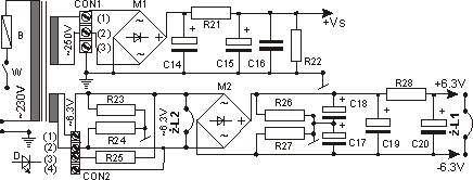
With regard to hum, 50 Hz should not be troublesome with proper location of everything. You can also raise the potential of the filament 10-15V above the cathode potential.
Excitation - it's not really a "positive ear", it would connect almost all the time. The question is whether this is not a case assembled on the table, no screening, etc. If it is better without the ears, it must be corrected - phase shifts cause the formation of positive feedback around the upper end of the band.
Although, the diagram looks good in this respect.


 because at the moment I do not have such a filtration system