logo elektroda
logo elektroda
X
logo elektroda

DIY RIAA Preamplifier with PCL86 Lamps: MM Insert, Anodic Power Supply +300V, 50W Transformer

fafikdog 9381 19
ADVERTISEMENT
Treść została przetłumaczona polish » english Zobacz oryginalną wersję tematu
  • #1 13324202
    fafikdog
    Level 12  
    I have the opportunity to buy a DIY preamplifier (infinite - no housing) on PCL86 lamps.
    Description of the amplifier:
    "amateur-made and well-functioning stereo preamplifier with RIAA correction characteristics for turntables with MM insert, made on PCl86 tubes." Preamplifier without casing and mechanical construction components Component set Complete and efficient Riaa preamplifier board with PCL86 elements and lamps Anodic power supply board + 300V. Power supply lamp board with 300mA current stabilizer Power transformer about 50W 220 / 250V-125mA, 28V-0.4A For this design is documentation of connections and schemes according to which this preamplifier was made. Pre-amplifier made on these lamps It is possible to mount this preamplifier inside the power amplifier, and mount it in an interesting housing. The PCB with the preamplifier and the power supply made by printing (hand-drawn), correction elements on the universal board, glow plug board on the universal board. with behavior m safety rules (it has one carcase corner removed, which has no effect on the parameters and use goes). General dimensions: 13 / 8cm / high pre-amplifier plates with 5.6cm elements. With 13cm tubes. 6.3cm lamp spacing. Mounting holes 11.8 / 6.8cm.fi.5.5. Anode power supply plates 8.7 / 5.1cm / height 3.5cm. Set open montaz.8 / 4,5cm.fi.3mm. Glowing plates 6,7 / 2,3cm / height 4cm. Transformatory outline marker 8.5 / 7cm / height.8cm. "
    Description, description, but I asked a few questions of the seller, below the questions and answers:
    1- what was the preamplifier modeled on?
    Ad.1 - on the German construction, I found a diagram on the net. Elektor magazine. The board adopted from EDW 01-2005.
    2- steaming lamps?
    Ad. 2- no, but the voltages on the anodes vary in the order of 2V.
    3- lamp operation adjusted?
    Ad. 3- no, but the values of the elements resistors in accordance with the diagram. Electrolytes in the order of capacity wolfness. the power supply is also compatible.

    And here is my question: how do you view such a construction?
    Is it right to play well? I do not have the opportunity to listen before buying ...
    DIY RIAA Preamplifier with PCL86 Lamps: MM Insert, Anodic Power Supply +300V, 50W Transformer
  • ADVERTISEMENT
  • #2 13325271
    jsk3
    Level 14  
    Why is this powerful lamp (PCL86) for the preamplifier? Besides, it's also a power eater. There are many proven, classic designs on the internet. As for me it's a mess, but someone can find the justification for using the final tube as a preamplifier.
  • ADVERTISEMENT
  • #3 13325912
    fafikdog
    Level 12  
    It does not matter if it's RIAA?
  • #4 13325971
    Futrzaczek
    VIP Meritorious for electroda.pl
    fafikdog wrote:
    It does not matter if it's RIAA?

    RIAA is the name of the curve that describes the frequency characteristics of the preamplifier.

    fafikdog wrote:
    And here is my question: how do you view such a construction?
    Is it right to play well? I have no way to listen before I buy ...

    It sounds like sound, but it can roar.
    I have never made such an experiment (there are many other lamps much better suited for this purpose), but I would not expect a revelation.
  • #5 13328376
    aksakal
    Tube devices specialist
    In amps of a similar type, lamps with very low noise are usually used, because its sensitivity should be quite high. Frequently, EF86 or special triodes are used in the first stage. Simply, for the experiment, you can use the indicated lamp, the practice will show that it came out.
  • #6 13338635
    Tomek Janiszewski
    Level 32  
    aksakal wrote:
    EF86 or special triodes
    most often used in the first stage
    ECC808 (not to be confused with ECC88 or E88CC which have parameters and purpose completely different). They have static parameters identical to ECC83, but they are equipped with an inter-system screen and prevents interference from the incandescence to the lamp electrodes. similarly to the EF86 and EF83 pentodes dedicated for audio applications.
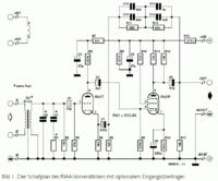
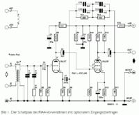
    Here, however, someone apparently to use garbage for non-standard purposes. This is also evidenced by the in the form of inserting a second pentode unblocked with a resistor capacity of a significant value into the net. It may be right only in for which one of the normal states is overloading of the final stage, here it causes a harmful increase in the end stage input capacity (due to the capacity between the first and second mesh multiplied by the Miller effect), which heavily loads the degree triode working on a high 220k? anode resistance. In correctly constructed voltage stages with pentodes, the second mesh connects through the capacitor to the mass (sometimes to the cathode, if a CVT signal is sent to it).
    C3 and C7 capacitors in the cathode and triode grid are unnecessary. Their absence would not cause a significant shift of the lamp's working point, whereas the fewer elements in such sensitive places, the smaller capacitances dispersed through which interference could penetrate. The fact that this full improvisation also testified by the marked polarity of electrolytic capacitor C3: apparently the author was not able to decide how it should be. In the meantime, if you already use it - it would be enough to swap the R2 and R3 resistors, and then a 47nF film capacitor would suffice.
  • #7 13339167
    aksakal
    Tube devices specialist
    Dear, ??m??! I read the topic many times, but I did not find the ECC808 lamp in my friend's posts. And one more reminder, why so many theories, it may be better to propose a specific scheme, there will be more benefits for the author of the topic. I think that not everyone who creates a subject wants to become an expert in radio technology, he needs help in a specific situation http: //www.radiolamp.ru/shem/vinil/ There are 14 patterns on this website.
  • #8 13339541
    fafikdog
    Level 12  
    Tomek Janiszewski wrote:
    aksakal wrote:
    Frequently, the first stage uses EF86 lamps or special triodes

    ECC808 (not to be confused with ECC88 or E88CC which have parameters and purpose completely different). They have static parameters identical to ECC83, but they are equipped with an inter-system screen and prevents interference from the incandescence to the lamp electrodes. similarly to the EF86 and EF83 pentodes dedicated for audio applications.
    Here, however, someone apparently to apply to unusual goals. This is also evidenced by the laymen manner in the form of inserting a second pentode unblocked with a resistor capacity of a significant value into the mesh. It can only be right in for which one of the normal states is distortion of the final stage, here it causes a harmful increase in the end stage input capacity (due to the capacity between the first and second mesh multiplied by the Miller effect), which heavily loads the degree triode working on a high 220k? anode resistance. In correctly constructed voltage stages with pentodes, the second mesh connects through the capacitor to the mass (sometimes to the cathode, if a CVT signal is sent to it).
    C3 and C7 capacitors in the cathode and triode grid are unnecessary. Their absence would not cause a significant shift of the lamp's working point, whereas the fewer elements in such sensitive places, the smaller capacitances dispersed through which interference could penetrate. About the fact that the full improvisation also provides practical selected polarity electrolytic capacitor C47: apparently the author could not decide how it should be. And in the meantime, if you use it already - it would be enough to swap the resistors R3 and R3 , and then a foil condenser with 47nF
    capacity would


    Explain in bold please ...
    And how the schematic has to your explanations.
    DIY RIAA Preamplifier with PCL86 Lamps: MM Insert, Anodic Power Supply +300V, 50W Transformer
  • #9 13339861
    Tomek Janiszewski
    Level 32  
    Excuse me, of course, a typo, as in the case of C47 (it should be C3). I've already corrected.
  • ADVERTISEMENT
  • #10 13339880
    fafikdog
    Level 12  
    And what about the diagram?
    Is it incorrect too?
    I will emphasize here that it is not the work of the pre-contractor.
  • #11 13340971
    Futrzaczek
    VIP Meritorious for electroda.pl
    fafikdog wrote:
    And what about the diagram?
    Is it incorrect too?

    So it is repeated again: this scheme has a chance to work, but the system based on it will have much worse parameters [mainly in terms of adding to the signal of interference] from something tried and tested.
    You can experiment, but this is not the way.

    fafikdog wrote:
    mark here that it is not the work of the pre-contractor.

    I think em you ate ;)
  • #12 13341365
    aksakal
    Tube devices specialist
    Dear Colleagues, The fact that it is not labeled polar ?3 is not a mistake! This is a special electrolyte capacitor that does not have a polar! If you look at ordinary electrolyte capacitors, their leads have different lengths and symbols of the minus sign, au capacitors without polar output of the same length and no polar symbol.
  • #13 13342625
    Tomek Janiszewski
    Level 32  
    aksakal wrote:
    Dear Colleagues, The fact that it is not labeled polar ?3 is not a mistake! It's a special electrolyte capacitor that does not have a polar!

    Bipolar capacitor? In the loudspeaker crossover diagrams (where often such capacitors are used, despite the mediocre parameters), I have not met such a symbol so far. Here, at constant voltages and voltages at the millivolt level, each capacitor will work equally, regardless of the direction of switching. Its shorting also will not change anything.
    On the other hand, the electrolytic capacitor C5, which spans both stages, is completely out of place. And the capacity too large at least by an order of magnitude, and more importantly - under no circumstances should it be an electrolytic capacitor! Its leakage current (especially directly after switching the power on after a longer break in use, when the condenser was partially dislodged) will cause harmful displacement of the pentode working point. More and more I am confirmed in the conviction that konstruktorzyna simply fuck first transistor circuit from the shore, pressing to him a lamp which he just nawinęła. :oops:
  • #14 13342966
    aksakal
    Tube devices specialist
    http://kxk.ru/dustyattic/v1_731156__.php On this web page, a fragment of the diagram with the designation of non-polar capacitor - ?1 50 uF. Currently, these capacitors are used in TVs, amplifiers, medical apparatus and still in a lot of schematics. I am surprised that you have not seen such a symbol

    Added after 8 [minutes]:

    PS-http: //www.novacon.com.br/audioconst3.htm And this is a website from Brazil. These are RIAA amplifier diagrams and one color tone regulator scheme that is very similar to the amplifier that we are discussing.

    Added after 5 [minutes]:

    If the appointment does not work, copy and put in a row of Google searches. http://www.novacon.com.br/audioconst3.htm

    Added after 1 [hour] 6 [minutes]:

    Friend, fafikdog! I give you a website, where all the necessary documentation for your amplifier is available, but it is in German. The amplifier's chart was published in the magazine Elektor 12/2000. "This is a serious journal that has good authority among amateur audio technicians. Http://www.hobbielektronika.hu/forum/getfile.php?id=73121
  • #15 13344026
    OTLamp
    Tube devices specialist
    Tomek Janiszewski wrote:
    not to be confused with ECC88 or E88CC which have parameters and purpose completely different

    As for the destination - these millions of oscilloscopes are poor with E88CC packed with X and Y amplifiers. Probably the minimum sensitivity is so with 0.5V / d, because the lower voltages will not strengthen anything because of this other purpose ... I do not mention these Siemens' 'noodles' who loaded the E88CC into professional studio preamplifiers ...
  • #16 13345191
    Futrzaczek
    VIP Meritorious for electroda.pl
    OTLamp wrote:
    Regarding the destination - these millions of oscilloscopes are poor with E88CC packed with X and Y amplifiers. Probably the minimum sensitivity is so with 0.5V / div, because the lower voltages will not strengthen anything because of this other purpose ...

    It is already malicious to rip out the context. Tomek Janiszewski clearly wrote:
    Tomek Janiszewski wrote:
    ECC808 (not to be confused with ECC88 or E88CC which have parameters and purpose completely different). They have static parameters identical to ECC83, but they are equipped with an inter-system screen and prevents interference from the incandescence to the lamp electrodes.

    ECC808 is electrically similar to ECC83.
    ECC808 has a designation similar to ECC88.
    ECC808 is not electrically similar to ECC88.
    ECC808 was developed for other purposes than ECC88 / E88CC.

    So where are you looking for a problem?
  • #17 13346044
    OTLamp
    Tube devices specialist
    Futrzaczek wrote:

    It is already malicious to rip out the context.

    Rather, you do not quite understand the context ... I've broken out what I'm referring to, so what did I break out?


    Futrzaczek wrote:

    ECC808 is electrically similar to ECC83.

    I wrote somewhere that it is different?


    Futrzaczek wrote:

    ECC808 is not electrically similar to ECC88.

    I wrote somewhere that it is?
    Futrzaczek wrote:

    ECC808 was developed for other purposes than ECC88 / E88CC.

    Among others to sensitive broadband amplifiers, including m.cz.
    Futrzaczek wrote:

    So where are you looking for a problem?

    I'm not looking, I'm pointing. In this case, mindless interpretation of labels.
  • #18 13346063
    Futrzaczek
    VIP Meritorious for electroda.pl
    OTLamp wrote:
    Including to sensitive broadband amplifiers, including m.cz.

    Since there is something broadband and bandwidth that includes m.cz., it is rather clear that to the very m.cz. you can use it too.

    The only question is, what is this about the meager preamplifier on PCL86?
  • ADVERTISEMENT
  • #19 13346089
    OTLamp
    Tube devices specialist
    Futrzaczek wrote:

    Since there is something broadband and bandwidth that includes m.cz., it is rather clear that to the very m.cz. you can use it too.

    Unfortunately, it is not clear to everyone, that's why I left. Especially that TJ is known (at least to me) from his all-round approach, meaning E88CC only to cascade and nothing else.
  • #20 13468498
    fafikdog
    Level 12  
    The author of the equipment also died ...
  • Topic summary

    The discussion revolves around a DIY RIAA preamplifier utilizing PCL86 tubes, which has raised questions regarding its design and suitability. Participants express skepticism about using PCL86 due to its high power consumption and potential noise issues, suggesting that other tubes like EF86 or ECC808 are more appropriate for low-noise applications. The RIAA curve's significance in audio quality is acknowledged, with some contributors advocating for proven designs over experimental setups. Concerns are raised about the use of non-polar capacitors and the overall circuit design, with suggestions for alternative schematics and components to improve performance. The conversation highlights the need for practical guidance and specific circuit recommendations for those less experienced in audio electronics.
    Summary generated by the language model.
    ADVERTISEMENT