Elektroda.com
Elektroda.com
X
This content has been translated flag-pl » flag-en View the original version here.
  • ECL86 and EM84 Tube Amplifier - PCB

    Hello everyone

    Today I would like to introduce you to the design of a tube amplifier, this is my second tube design. After the successful construction of a long wave tube radio receiver - link below

    https://www.elektroda.pl/rtvforum/topic3549270.html

    I decided to build a tube amplifier - as the budget for a tube amplifier was not too big, I decided to use what I had at hand, i.e. components from old Bambino turntables and ZK120 and ZK140 tape recorders.

    My assumption was to build a low-power stereo amplifier with a drive indicator. The circuit includes two ECL86 tubes and two EM84 magic eye tubes, for this I used two Bambino output transformers and two mains transformers. I decided to make two separate monoblocks, i.e. completely separate mono amplifiers in one housing.

    I decided to make a PCB for the amplifier - just like before, I decided to make a PCB design in Eagle, and then improve the track layout in GIMP so that the PCB looks like the one from the AM radio to which I gave the link above.

    As I had not done a tube project using high anode voltages before, after thinking about it, I prepared a few PCBs:

    - Two mono amplifier PCBs
    - Two PCBs for the control indicator
    - Anode voltage switching delay board (ready-made board design)
    - Audio input selector board (not designed yet)
    - Two anode voltage stabilizer plates (not designed yet)
    - Phono preamplifier board (ready-made board design)

    On the amplifier board, I designed a high-voltage rectifier bridge, because so far the original selenium rectifier is used (one per channel) and an electrolytic capacitor from Bambino (I plan to put only lamps without transformers on the housing and this electrolytic capacitor - actually two capacitors in one housing). However, transformers will be built in due to the high voltage present on them - therefore for safety reasons.

    It is true that the design of the amplifier itself is already started and the only thing left to do is make a housing for it - I will do it in spring or summer, depending on the weather (outside temperature). I plan to make the housing of wood, but I haven't thought about the details yet.

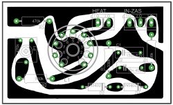
    Below I present photos of PCBs
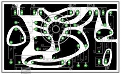
    ECL86 and EM84 Tube Amplifier - PCB ECL86 and EM84 Tube Amplifier - PCB

    The first board is the ECL86 amplifier. Description of the pins of the board:

    - ZAS - power supply - here we connect the power supply directly from the selenium rectifier + high power supply is on the left in the graphic and - on the right.

    - TR - loudspeaker transformer - connect the primary winding as shown in the diagram (it will be below)

    - HEAT - lamp incandescence - connect alternating voltage directly from the 6.3V mains transformer

    - STAB - the output to which the electrolytic capacitor is currently connected to the housing - connect in such a way that the outermost outputs go to the two pluses of the capacitor and the middle one is a minus, i.e. the capacitor housing (electrolytic capacitor used in turntablesThe Bambino has two capacitors in its housing, hence three outputs - two pluses and a minus on the housing). In the future, this screw connector will be used for a possible expansion of the amplifier with an anode voltage stabilizer, then the voltage stabilizer will be connected, looking at the graphic, from the right there will be the middle ground input and the left stabilized voltage output. When using such a stabilizer, it will be necessary to remove the 3.3k resistor - R9.

    - SP - i.e. speaker connection - connect the speaker there as well as the secondary winding of the speaker transformer.

    - IN - mono input of the amplifier.

    - P - potentiometer for volume control. Ultimately, it will be replaced by a jumper, and the audio signal directly from the chinch inputs will go to the stereo potentiometer, and then to the mono amplifier inputs (the mono potentiometer on the board will be replaced by a jumper)

    The second PCB is the mod indicator. Description of the pins of the board:

    - HEAT - lamp incandescent - connect AC voltage directly from the 6.3V mains transformer - together with ECL86 lamp incandescent (in parallel)

    IN-ZAS - power supply connector and feeding the input signal for the driver indicator. Looking at the graphic from the right, we have the signal input, the middle one is the power supply - we connect the high voltage there, which we take from the ECL86 amplifier board, and the leftmost terminal is ground. The potentiometer is used to set the signal level on the vacuum tube.

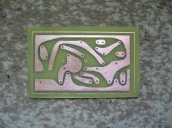
    I started making PCBs
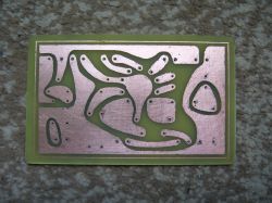
    ECL86 and EM84 Tube Amplifier - PCB ECL86 and EM84 Tube Amplifier - PCB

    Of course, I made two PCBs of both the amplifier and the indicator.
    To make everything look retro, I also decided to install resistors from that era obtained from turntables.

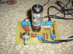
    Here is the finished ECL86 amplifier board (one channel of course)
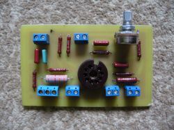
    ECL86 and EM84 Tube Amplifier - PCB ECL86 and EM84 Tube Amplifier - PCB

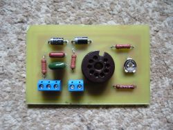
    And the control indicator board

    ECL86 and EM84 Tube Amplifier - PCB ECL86 and EM84 Tube Amplifier - PCB

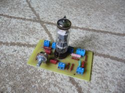
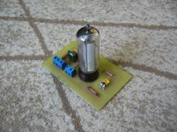
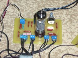
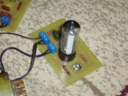
    After assembling one channel, the whole thing looks like this:
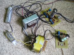
    ECL86 and EM84 Tube Amplifier - PCB ECL86 and EM84 Tube Amplifier - PCB ECL86 and EM84 Tube Amplifier - PCB

    The amplifier was launched - so far without an anode voltage stabilizer and without a delayed anode voltage system. These tiles are being prepared. Later, these circuits will be added and I plan to use some audio input selector. I also wanted to make an ECC83 tube preamplifier with tone correction, but so far I rejected this idea, why disturb the frequency response characteristics. There will also be an additional RIAA phono preamplifier based on an ECC83 tube. All boards with tubes will be GIMPed to make everything look nicer - the voltage stabilizer board for the delay of switching on the anode voltage and possibly the input selector will be made traditionally in Eagle.

    As for the sound quality - to be honest I did not expect such a good sound from this amplifier. I used used elements in this lamps - the costs incurred by me were minimal - I had all the things, I bought a laminate and ARK connectors and 3.3k resistors because those used in Bambino were larger, so I used newer ones to fit nicely to my PCB. Total costs PLN 30 + housing costs, I think about something made of wood. There will also be costs for additional delay plates and stabilizer. But I try to do everything with the items I have. From the ZK120 or 140 magnetophone I also have an ECC83 tube so it will be used for the phono preamplifier.

    But going back to the sound, I was a bit afraid of running this amplifier on a PCB - I read on the forum that bad path routing would result in hum, hum and other distortions, I designed the PCB myself and then finished the graphics in GIMP, made a thermal transfer, etched, soldered elements and commissioning - and here a pleasant surprise - nothing, no hums everything perfectly in the absence of an input signal silence, some wrote that you need to connect one leg of the radiators to the ground because there will be a hum, I did not do it and it works perfectly (of course, if necessary, you could to connect it with a cable).

    After connecting the second PCB, there are no hums either. Everything works better than expected.

    I present the diagrams, I slightly modified the original diagram from the Bambino turntable
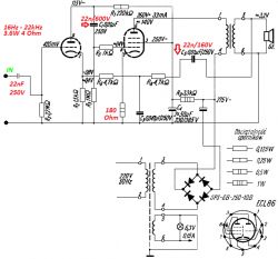
    ECL86 and EM84 Tube Amplifier - PCB

    As well as the magic eye diagram

    ECL86 and EM84 Tube Amplifier - PCB

    For all those who decide to make a thermal transfer plate, there are two versions in the file: in the first version, the tubes are mounted from the side of the elements (as in my case), and in the second version from the print side, which will allow the amplifier to be mounted in the housing with the protruding tubes.

    Ready pdf files for thermal transfer are attached.

    And now something for those who would like to get the tiles for this amp for free, as I designed the tiles, I made the track tiles in Eagle for the start, and the second set of tiles in Gimp, as I made the amp on the Gimp ones, it's the ones from Eagle so they are left for giving.

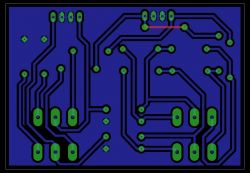
    This is what the control indicator board looks like (the lamp from the elements side)
    Of course, there are two pieces of these tiles to give away.
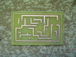
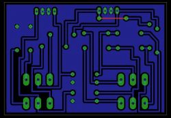
    ECL86 and EM84 Tube Amplifier - PCB

    And this is what the power amplifier board looks like (the tube from the elements side)
    Two pieces of these tiles are also available for donation.
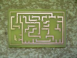
    ECL86 and EM84 Tube Amplifier - PCB

    I did not run the amplifier on those PCBs from Eagle - the distribution of elements is the same, the paths are different - it is difficult to say whether there will be any hum on these PCBs, especially the power amplifier ones.

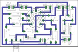
    Here is the distribution of elements on the Eagle boards.
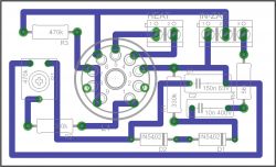
    ECL86 and EM84 Tube Amplifier - PCB ECL86 and EM84 Tube Amplifier - PCB

    And I still have a set of four PCBs to hand over, like the ones on which I made the amplifier - 100% checked.

    All the tiles I have left have the correct connections and are drilled.

    So, if someone wants to try to make an amplifier on these PCBs, write me a letter. I only have two sets of tiles, so the first two people who write and pick up the tiles will get them. The first person will get the GIMP version and the second person will get the Eagle version (angular paths). If it is free of charge with self-collection, and if it comes with delivery, shipping costs are reimbursed. I ship the tiles.

    In case you had any questions, I'll be glad to help. I am waiting for comments, it is my twenty-fourth published project. I am asking for your understanding, I read the regulations and I think that I did everything in accordance with them.

    Cool? Ranking DIY
    About Author
    DJCheester
    Level 24  
    Offline 
    DJCheester wrote 1414 posts with rating 779, helped 75 times. Live in city Bełchatów. Been with us since 2011 year.
  • #2
    ak44
    Level 27  
    Delayed activation of the loudspeakers is not needed if the filament and anode voltage are applied at the same time.
  • #3
    Anonymous
    Level 1  
  • #4
    DJCheester
    Level 24  
    Hey, there was supposed to be a delay in switching on the anode voltage but I wrote late and the error broke in, I'm correcting it, thanks for the info

    Of course, it is about the anode voltage, and applying it to hot lamps increases the lamp life.

    As for the tiles, they were designed in Eagle and the tracks were drawn in Gimp - I recommend reading the post about the AM radio from the link I gave there, everything is described.

    Best regards ...
  • #5
    pawelr98
    Level 39  
    It is a pity to waste ECL86 on mine.

    The first one currently costs a minimum of PLN 40, as much as the new EL84.
    PCL86, on the other hand, PLN 10-15 for a tube with a decent emission or PLN 20 for NOS.
    It was better to sell those ECL86s and buy yourself a new PCL86.

    It would be good if the board was already factory-equipped with a filament voltage multiplier. Then it is easier to switch to PCL lamps.

    Another thing.
    Did the colleague check the glow voltage?

    The transformers in these tape recorders were designed for 220V.
    Currently, there is 230V in the network. Instead of a 6.3V glow, the partner has 6.6V or even more.
    If it is too large, it is usually enough to add a small resistor.
  • #6
    DJCheester
    Level 24  
    Hello

    The ECL86 are recycled, so I don't feel sorry for them, besides this is my first tube amplifier so I treat it as a science. I suspect that these lamps also do not have a good emission - a colleague is right 6.8V incandescent and a resistor has already been added in series for the filament voltage.

    With a duplicator one might think for the future ...

    Best regards ...
  • #7
    pawelr98
    Level 39  
    Lamp emission can be judged from the anode current.

    The anode current is the drop across the cathode resistor. This drop is also the negative voltage of the first grid.

    Just compare with the characteristics in the documentation.
    Any "matching" (especially to obtain the second grid voltage that occurs on the characteristics) can be accomplished by inserting a resistor in series with the power winding.

    Since a colleague has an inflated glow, it can also be assumed that it is anode overestimated.
    It doesn't have to be that way though. The rectifier that my colleague used is selenium.
    It is old and probably has increased internal resistance.

    You have to be careful with them. They like to light up on the occasion, producing a cloud of toxic fumes.

    And here you can play with the "retro" delayed anode switching system.
    A silicon rectifier bridge and a junk PY88 in series (new one costs PLN 2-2.5) or another cheap rectifier lamp. It will delay the appearance of the anode voltage and reduce it (which will be necessary anyway due to the increase in network voltage).
  • #8
    JAMA15
    Level 13  
    I put together a similar one, only powered from one network transformer and assembled in a spider.
    Nevertheless, the lamp on the tiles does not suit me, although it certainly looks nicer ...
    In the attachment my housing - maybe some detail will inspire you during the construction - good luck.
    ECL86 and EM84 Tube Amplifier - PCB
  • #9
    zworys
    Level 39  
    Nice, thoughtful design, but some ideas are an excess of form over content. For these lamps there is no need to use delayed anode switching, it is not the power and voltage. If this is to be a testing ground then OK. Now I would suggest to my colleague, after the appropriate arrangement of the elements in the housing, place the entire single amplifier on one PCB. The tangle of cables and most of the input cubes will disappear. The anode power supply can be properly separated. Only the filament power supply can be led using a twisted pair cable directly to the pins of the lamp base.
  • #10
    DJCheester
    Level 24  
    Hey, this is the first version - just to hear the "lamp".

    Now I can see that with subsequent versions, if there are any, there will probably be a power supply with anode voltage stabilization - connected at once with a voltage multiplier for PCL - because it's a good idea and I will definitely use it.

    As you write, this is my first such amplifier and I wanted to experiment with caution, of course, because the circuit has high voltage.

    Maybe you can give some ideas for a proven HV voltage stabilizer and an input selector because I haven't started designing it yet.

    Please ...
  • #11
    zworys
    Level 39  
    The tube is not a transistor (anyway, stabilization is not used for transistor terminals either) - it does not require stabilized voltage, at least in a system like here. In order for the anode voltage to be "stiffer", it is enough to have a transformer with appropriate efficiency and a rectifier or diode bridge (it has a lower internal resistance than a selenium stack). Stabilization makes sense for sensitive tube preamplifiers and voltage amplifiers.
  • #12
    pawelr98
    Level 39  
    It is worth introducing stabilization for another reason.
    Mains voltage fluctuations.

    It is true that the lamps are quite resistant to exceeding parameters, but it is still worth protecting them, especially if they are expensive and are no longer manufactured. The ECL86 is worth it because it's hard to find new ones and the prices of the current ones are rising.

    When the prices of the ECL86 exceed the absurd level, audiophiles will probably turn to the PCL86 (although it is not so certain, after all, the tube is "television").

    Structurally, the matter is very simple. Bipolar transistor or mosfet, zener and resistor. If the voltage values are selected correctly, the power of the losses will be a few watts maximum.
    And you can also play with the implementation of the triode lamp mode.
    Some amps even have Triode / Pentode switches that switch the second grid accordingly.

    In my experimental tube amplifier I have anode stabilization, because in the final stage there is a triode with very low internal resistance (400?, 6S19P). For this the transformer gives 2x300V and I need 185V (some breaks the resistor and some stabilizer). I do not stabilize the filament, only resistors in series (0.1? + 0.22? ;) . Sometimes I just close the 0.1? resistor with a switch if the mains voltage drops below 220V (the incandescence is already approaching 6V).
  • #13
    lukaszd82
    Level 30  
    Maybe someday I will also build a tube amplifier, especially since I have a tube box. It is a pity that there is no time, and several other ideas are being implemented.
    I will be observing the topic carefully, I will be happy to see the end result. Maybe a video of how the whole thing works at the end :)

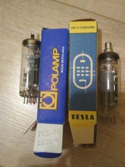
    By the way, I have a lot of tubes as below. Which of them are worth using for an amplifier?


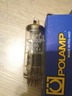
    I have some PCL86 (POLAMP) and PL81 (TESLA) lamps. I can resell or exchange for something that interests me (lcd 4x20 and possibly other usable with atmega, stm32). Alternatively, I am asking for info on pw.
    ECL86 and EM84 Tube Amplifier - PCB ECL86 and EM84 Tube Amplifier - PCB ECL86 and EM84 Tube Amplifier - PCB o
  • #14
    tytka
    Level 21  
    DJCheester wrote:
    I did not run the amplifier on those PCBs from Eagle - the distribution of elements is the same, the paths are different - it is difficult to say whether there will be any hum on these PCBs, especially the power amplifier ones.


    Honestly, when I look at these tracks from Eagle, I have the impression that the designer does not know the basics of handling it.
    Why "broken" paths at right angles? After all, it only increases their length. This may adversely affect the performance of the device.
    And it was only necessary to choose another option to "break" the paths.
  • #15
    DJCheester
    Level 24  
    Hello

    The paths were designed with regard to later changes in Gimp - hence the angular ones paths I was more concerned with the distribution of elements convenient for me ...

    As for the PCL86 tubes, you can safely use for my amplifier, the incandescent lamp is led separately on the board, so between the transformer and the amplifier board you should give a voltage multiplier and the tube will be able to work in my amplifier.

    Just one PCL86 tube after such a modification (adding a duplicator) will get you one channel (the tube has a triode and a pentode), so two tubes and you have a stereo, but without the magic eye - you only make the amplifier board.

    For this you need to have loudspeaker transformers, I have one from spoolers with 5 pcs, so I can resell it, you only need to arrange it transformer mains - preferably from the old Bambino adapter or other with 250V anode and 6.3V glow voltages, but you can also give it straight away transformer with 12.6V filament, which will simplify the system because you will not have to give a voltage multiplier ...

    Best regards ...
  • #16
    tytka
    Level 21  
    DJCheester wrote:
    The paths were designed in such a way as to take into account the later changes in Gimp - hence these angular paths were more important to me about the layout of elements convenient for me ...


    Placement is one thing, routing is another. You can arrange elements in the same way, and lead paths in a completely different way, as can be seen in the description of this project.
    And if there were assumptions that the Eagle project was only a starting point for further development, I ask. What was the point of wasting laminate and etchant on this messy track design?
  • #17
    DJCheester
    Level 24  
    The sense that they look retro and hand-drawn, I personally like them very much in combination with tube circuits because I associate them with PCBs, for example old reel to reel tape recorders, e.g. ZK120.

    And if some people do not like it, it is difficult, I can not help it, the project is a kind of idea, but the publication nowhere says that you have to do this, if you like it, please provide thermal transfer and if not, it is difficult to do according to your own and better ideas.

    PS. PCBs still to be delivered. Willing people should write to PW.

    Best regards ...
  • #18
    tytka
    Level 21  
    I'm not talking about picking on. This is not my intention.
    As you know, when designing paths, you should, among other things, keep them as short as possible. Unfortunately, breaking them always only at right angles is not conducive to this.
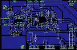
    For example, compare these two sample tiles. Both projects made in Eagle.

    ECL86 and EM84 Tube Amplifier - PCB ECL86 and EM84 Tube Amplifier - PCB
  • #19
    Anonymous
    Level 1  
  • #20
    zworys
    Level 39  
    Gentlemen, no exaggeration - in this project and for these frequencies, the shape and length of the tracks do not matter. He would only suggest increasing their width, there is room for it (at least for most), less etching, better solderability. Thin paths are not at all a sign of "modernity" of the project ...
  • #21
    DJCheester
    Level 24  
    Hey, as I wrote earlier - my project is like someone wrote a testing ground before and treat it like that, I learn on it myself, it is my first tube amp and probably the last one because I wanted to listen to the lamp and I just did it, but for now I will finish the project.

    As for the PCB, I kept larger intervals due to the high voltage in the system.
    Besides, I don't like "polygons" and I avoid them wherever I can.

    And by the way, I like angular things, I drive an angular car and I have a lot of things at home, let's call it from the previous era.

    And as for PCB, of course, each of you can have your own opinion and it's good, I want someone to want to build this or a similar amplifier read the topic and read the opinions and tips of all of you and built a better one than mine, I also read when I started the project dozens of pages devoted to tube circuits as well as posts on the electrode. I made, I am satisfied, above all, with the final effect - the sound quality, because I thought that it might turn out to be a huge flop that it would hum when connected and you can't listen to it, but fortunately it did not happen and I can guarantee it to all those who want to make such tiles like mine, but of course the project is open and suggestions for changes as well as comments are welcome.

    My friend, I can share .brd projects if you have time to correct them as you see fit and thus you will contribute to the development of this layout.

    Best regards ...
  • #22
    zworys
    Level 39  
    DJCheester wrote:
    I can guarantee it to all that tiles like mine will want to do,

    Buddy, do not guarantee because tiles are not everything. If someone does the wrong wiring, they may be unpleasantly surprised and upset. This should also be remembered - that it should not be "cable lettuce" but made and run according to the rules.
  • #23
    tytka
    Level 21  
    That's right buddy graph but as a colleague noticed Kraniec_Internetów , the idea was to point out to the author of the project that the approach he presented was not correct. In this project, it may not matter, but if a colleague of the author develops such a habit and starts more serious projects, he may have trouble with his tiles. This forum is, after all, also to suggest more appropriate solutions, to indicate more accurate methods of solving a given issue.

    And on the width of the paths, there is really no need to save.

    Added after 7 [minutes]:

    DJCheester wrote:
    My friend, I can share .brd projects if you have time to correct them as you see fit and thus you will contribute to the development of this layout.


    If you want, we can do it.
  • #24
    DJCheester
    Level 24  
    Hey wires, what you see in the picture, it is connected quickly to start, but the housing will be all tied up and released as it should - so far I have not published the device in the housing, then I will be able to comment on the wiring and any errors in it What am I doing.

    Besides, probably a person who has no idea about tube circuits will not start to install it because you need to have some knowledge about it, I already wrote about the risk that the system has high anode voltage.
  • #25
    tytka
    Level 21  
    It's off topic, but


    DJCheester wrote:
    Besides, probably a person who has no idea about tube circuits will not start to install it


    You assume that absolutely all people are reasonable, I don't know if this is the correct approach. Life shows something else.
    How many people do something without even knowing the basic basics of it.
  • #26
    tytka
    Level 21  
    DJCheester wrote:
    Besides, I don't like "polygons" and I avoid them wherever I can.


    It is worth liking them, you can then make such paths:

    ECL86 and EM84 Tube Amplifier - PCB
  • #27
    DJCheester
    Level 24  
    Hi

    Not that I do not like the polyon board in the visual sense, but unfortunately after 25 years in electronics, the eyesight slightly refuses to obey, and the polygon board without soldermask is a pile of short circuits and must be desoldered later. What may seem funny to some, what I write but with age and sometimes, unfortunately, it does.

    But let's get back to the topic of construction, if something else besides PCBs has to be added.

    Best regards ....
  • #28
    cirrostrato
    Level 38  
    pawelr98 wrote:
    The transformers in these tape recorders were designed for 220V.
    Currently, there is 230V in the network. Instead of a 6.3V glow, the partner has 6.6V or even more.
    If it is too large, it is usually enough to add a small resistor.
    Did a colleague have in his hand (the author of the topic mentioned the TG from the ZK120 / 140 but did not write anything about TS from it) a "power transformer" from such a tape recorder?
  • #29
    discawery
    Level 11  
    Hello!
    Sorry to dig it out, but I have a question for the author, possibly other forum members willing to help.

    I made a thermal transfer of the plate thrown in by the author (mounting the lamp from the side of the paths, because it is supposed to go above the housing), I etched it, all the paths are fine, I tinned them.

    I also have bamboo elements - including the TG2.5-1-666 speaker transformer.

    After folding, however, the system clearly hums (hum louder than the signal), I will immediately add that the signal cables are short and shielded, the heating cables are on the twisted pair. I will try to solder the incandescent resistor so that it is about 6.3v. The lamp is fully operational, in a different arrangement it does not cause hum. At the moment, the system is not grounded to any metal chassis. I do not think I need to ground the secondary winding of the speaker transformer, it is on a common path with the ground of the circuit to the PCB.

    Actually, the only difference between the circuit assembled by me and the author is probably a different speaker transformer - as I wrote, I have tg2.5-1-666, and a silicon rectifier bridge instead of a selenium stack, but this probably has no effect on the hum ...

    I do not have any filtering capacitors behind the rectifier bridge, only a bamboo 2x50uF capacitor mounted exactly like the author's, in the STAB connector.

    Tomorrow I will measure the values of all components, but this is probably not the problem, I measured everything directly before soldering.

    Do you have any ideas what can cause such a clear hum? Or some mistakes made most often by beginners, because this is my first tube amplifier.
  • #30
    Krzysztof Kamienski
    Level 43  
    discawery wrote:
    Do you have any ideas what can cause such a clear hum? Or some mistakes made most often by beginners, because this is my first tube amplifier
    Invert the terminals of the speaker transformer on either winding. Maybe you have positive feedback instead of negative?