logo elektroda
logo elektroda
X
logo elektroda

"WZMAK" - That is, an amplifier on 6P6S, ECC82 and EF86

Pltin74 3288 39
ADVERTISEMENT
Treść została przetłumaczona polish » english Zobacz oryginalną wersję tematu
  • Hello everyone!

    I come to you with a project that dragged on for me for almost 4 years - a tube amplifier, which was my school of tube electronics. During this time I made a lot of mistakes, learned a lot and today I can say with a clear conscience that "I already know something". 😊

    Initially, this was to be a clone of the schematic-based Ampex 2012, but it soon became apparent that I did not yet know at that time how the input pentode behaved. Its gain was too high in this circuit, which caused problems - the original design was designed for low input amplitudes.

    The tubes, transformers and components were already bought, so something of my own had to be designed.

    There was also hum and not much power per channel. I dealt with the former by:
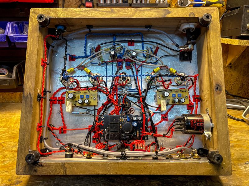
    - ground in a star topology, very carefully done,
    - and using a capacitance multiplier instead of a heavy and expensive choke.

    As for the power - the problem was trivial: a badly chosen resistance of the negative feedback loop. After correction - the power was back in place.


    What did I add?
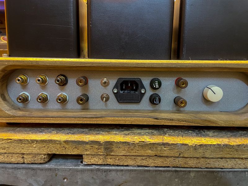
    - UL/Pentode mode switch - gives you the opportunity to experiment with the character of the sound.
    - Input selector
    - Switch between tube rectifier (GZ34) and silicon bridge - the circuit completely disconnects the GZ34, so it doesn't run and wear out.


    Technical extras:

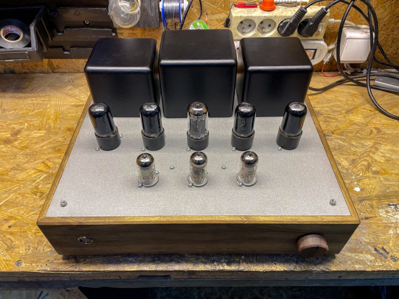
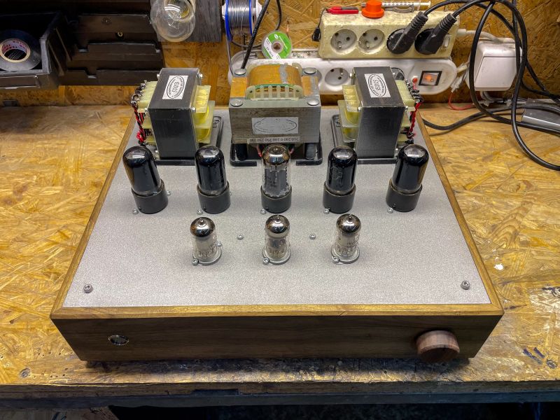
    I also used quite a few parts from the 3D printer - the largest being the transformer covers.

    I've tried to keep the interior aesthetically pleasing in a spatial style - I'm a big fan of spatial assembly and I think it looks and works great.


    Impressions
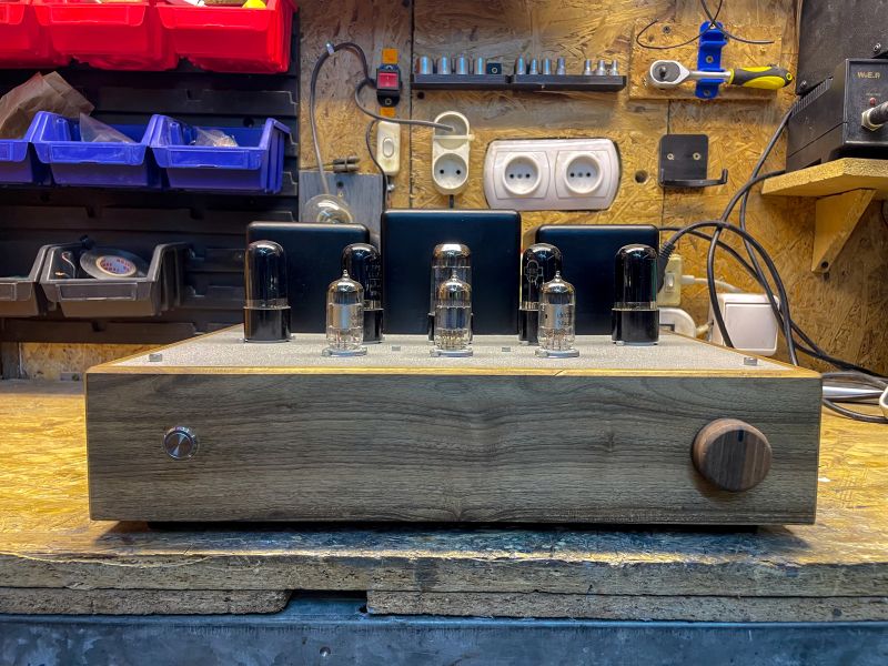
    - Looks? In my opinion - excellent.
    - Sound? Even better.

    In my opinion, the pentode mode beats the UL by a whisker - it gives more power and a characteristic "tube hoarseness". The sound is further 'compressed' by voltage drops on the GZ34, which adds to the atmosphere, but only when listening in 'full tube' mode.


    Concluding remark

    I've recently noticed a slight 50 Hz hum in tube rectifier mode - I suspect my GZ34 is running out (I've had an incident of sparking in the bulb), although it may also be a matter of some sort of ground loop - but not likely, as the sound is typical of mains frequencies.

    So on a day-to-day basis I listen on silicon, but I still plan to play around with a "pseudo rectifier tube" - i.e. two diodes + a power resistor.


    Photos:

    📸

    Tube audio amplifier on a workbench in a workshop. .
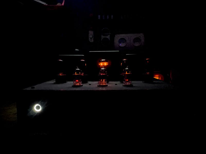
    Dark photograph of a tube amplifier with glowing tubes visible. .
    Tube amplifier with visible tubes and transformers on a workbench. .
    Tube amplifier with various tubes and transformers on a wooden and metal enclosure. .
    Rear panel of an amplifier with various connectors and a power socket. .
    Interior of a tube amplifier in a wooden case with red and blue wires. .

    Cool? Ranking DIY
    About Author
    Pltin74
    Level 7  
    Offline 
    Pltin74 wrote 121 posts with rating 86. Live in city Tęgoborze. Been with us since 2019 year.
  • ADVERTISEMENT
  • #2 21514986
    marweg1967
    Level 14  
    Congratulations on a successful build! Four years maybe, but you're happy with the sound effect too, and you've learned a lot in the process. And that's what it's all about.

    I'm guessing that the output is push-pull? What kind of output transformers did you give? Any off-the-shelf or custom made?
  • #3 21515365
    Pltin74
    Level 7  
    >>21514986 yes it is, these are transformers from Mr Ogonowski
  • #4 21515432
    acctr
    Level 38  
    Pltin74 wrote:
    When it came to power - the problem was trivial: badly chosen resistance of the negative feedback loop.
    .
    It was probably the gain that was too low and not the power?
    Helpful post? Buy me a coffee.
  • #5 21515637
    rosomak19
    Level 23  
    I too have been lurking lately , to make something more than my test 2xECL86 SE . From my resources I have dug out 4 PCC88 tubes and 4 PCL805 . Too bad I'm missing one PL500 for the PP. On the PCC88 maybe a preamp with tone control ? As for the PCL805 , I see that there was a power amplifier done on this in the Orgaphon 24 . Since I have it maybe I will see what comes out of it .
  • #6 21515702
    szeryf3
    Level 29  
    Congratulations on the design and construction.
    I like the underside very much.
    Don't give up on the rectifier tube.
    Were the transformers specifically chosen for this project?
    The night photo knocks it down
    Have you thought about lamp baskets?
  • #7 21515844
    dudik56
    Level 17  
    Nice design and nice assembly. The overvoltage appearing in the rectifier lamp could be from too high a voltage but it could also be an individual characteristic of the lamp. I once had such adventures and changing the tube helped.
    The front of the amplifier in a slightly "flinstonian" style , but quite consistent. Good that there are not too many visible screws ;) .

    I don't know how these carefully printed and machined transformer covers will stand up to prolonged elevated temperatures but they are in the cool style of the 1960s plastic world.
    In a few years the self-adhesive cable mounts usually stop 'holding' so I avoid them.
    An amp used on an ongoing basis is first and foremost a heater and such things are worth paying attention to.
    Good luck to you.
  • #8 21516410
    cirrostrato
    Level 38  
    rosomak19 wrote:
    Too bad I'm missing one PL500 for PP. At
    These lamps on Allegro now almost at the price of a bottle of natural sourdough for Christmas borscht, I have a lot, zero interest although prices tiny.
  • #9 21516727
    rosomak19
    Level 23  
    cirrostrato wrote:
    These lamps on Allegro now almost at the price of a bottle of natural sourdough for Christmas borscht, I have a lot, zero interest although prices are tiny.

    So I might ask , is it worth putting together a clone of such a Meloman 25 ? How did the original compare in terms of sound ?
  • ADVERTISEMENT
  • #10 21517044
    Pltin74
    Level 7  
    >>21515432 exactly, too little gain to drive a load with 12 watts from the datasheet ;) .

    bb2168d2d Added after 6 [minutes]:

    >>21515637 it's a pity that PCC88 is not the same as ECC88 just for a different voltage, but it's worth tinkering with something

    bb2168d2d Added after 1 [minute]:

    >>21515702 transformers are one of P. Ogonowski's models from his site. As for the baskets I honestly hadn't thought

    bb2168d2d Added after 4 [minutes]:

    >>21515844 screws are visible on purpose, in my opinion they add to the beauty, more so than rivets for example. The amplifier could have been lower, fact. and as for the ro covers, they are printed from a material that is more resistant to higher temps (up to 80 degrees) i.e. PET-G. the cable mounts have also been printed and glued with cyanoacrylate glue :D .
  • #11 21517089
    kris8888
    Level 39  
    Why the input selector on the back? Could you throw in a diagram of this amp as I can see quite a few differences from the original.
  • #12 21517470
    Pltin74
    Level 7  
    >>21517089 this is entirely my design, in the sense that it was originally going to be Ampex but however I redesigned it my way :p
  • #13 21517640
    rosomak19
    Level 23  
    Pltin74 wrote:
    It is a pity that PCC88 is not the same as ECC88 only for different voltage, but it is worth tinkering
    .
    Apart from the series glow , what is the difference between PCC and ECC ? The same as the PCL86 from the ECL 86 . Maybe in the tide of time I will assemble some preamp with tone control on these PCC88s and see how I perform .
  • #14 21517655
    żarówka rtęciowa
    Level 37  
    Hello

    rosomak19 wrote:
    Pltin74 wrote:
    It's a shame that PCC88 is not the same as ECC88 just for a different voltage, but it's worth tinkering with
    .
    Apart from the series glow, what is the difference between a PCC and an ECC? In the same way that PCL86 is different from ECL86? Maybe in a spur of the moment I'll assemble some preamp with tone control on these PCC88s and see how I perform.


    For dual triodes, the differences are only in the glow parameters. The ECL86 and PCL86 tubes also have different characteristics due to the supply voltages of the circuit for which they were originally designed.
  • #15 21518055
    kris8888
    Level 39  
    żarówka rtęciowa wrote:
    The ECL86 and PCL86 lamps also have different characteristics due to the supply voltages of the circuit for which they were originally designed
    .
    This is where you are wrong, these are identical tubes in terms of characteristics, they only differ in their glow parameters.

    Perhaps you are confusing this with a pair of PL84 and EL84? Because these are actually completely different tubes in terms of characteristics.
  • ADVERTISEMENT
  • #16 21518072
    gulson
    System Administrator
    Very nice construction, thanks for the presentations!
    How long did it take to build?
    Write me a PW with the Parcel Post and I'll send a small gift.
  • #17 21518155
    Pltin74
    Level 7  
    >>21518072 Thanks a lot! After redesigning without looking for any more shortcomings I think with all parts about a month. A bit long, but that's because I'm actually doing everything myself, apart from the case, transformers, rca sockets and the like ;)

    Added after 1 [hour] 1 [minute]: .

    >>21517089 .
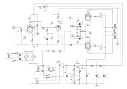
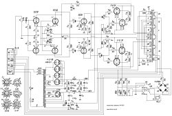
    please :)
    Electronic circuit diagram with vacuum tubes and components. .
  • #18 21518355
    Rocky Horror
    Level 31  
    Strange this resting current control. The potentiometer sliders are connected in parallel. No matter how you spin them, the voltage on the first grids of both tubes - more or less - will still be the same. There is also no sensible filtering, no capacitor to ground after diode D2 or even resistors R19 and R20. The result will be a large AC voltage on resistor R30 and consequently on the bypassed capacitors. This is probably where the 50Hz hum mentioned earlier comes from.

    What is the purpose of putting the source switch on the back?
  • ADVERTISEMENT
  • #19 21518529
    kris8888
    Level 39  
    In my opinion, the diagram probably contains errors. I don't know what the component values are, but according to this diagram, the V2A lamp of the phase inverter should not work at all.
    I also don't understand very well how the coils of relays K1 and K2 are controlled. They switch on by switching on the TR6 transformer ?
  • #20 21518736
    Pltin74
    Level 7  
    Rocky Horror wrote:
    No sensible filtering either, no capacitor to ground after diode D2 or even resistors R19 and R20. The result will be a large AC voltage on resistor R30 and consequently on the bypassed potentiometers with capacitors. This is probably where the 50Hz hum mentioned earlier comes from.
    fact, I had forgotten about this capacitor, but it seems to me that the cause of the 50hz is different

    Rocky Horror wrote:
    What is the purpose of putting the source switch on the back?
    purely visual, I wanted the front to be minimalist ;) .

    Added after 6 [minutes]:3298872ee

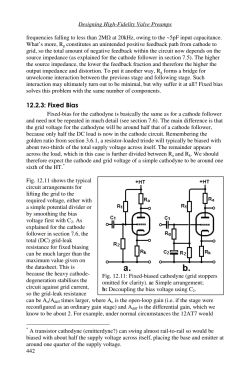
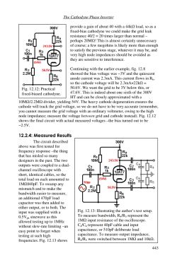
    >>21518529 >>21518529 why? The phase inverter is laughing all the way ;) subsection 12.2.3.
    Page from an engineering book showing electronic schematics and text about valve preamps.
    Phase inverter schematic with cathode configuration description. .

    kris8888 wrote:
    I also don't really understand how the coils of relays K1 and K2 are controlled. They are switched by switching on the TR6 transformer ?
    .
    there is a switch, fact - it is not on the diagram
  • #21 21518805
    Rocky Horror
    Level 31  
    Pltin74 wrote:
    fact, I had forgotten about that capacitor
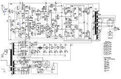
    And that's why it's worth following how it was done 50 years ago and before.

    Circuit diagram of a tube amplifier with component labels and connections. .
    Electrical schematic of a classic tube amplifier with control elements. .
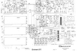
    Electronic schematic of the Eminent II T audio amplifier by Dynacord. .

    Quote:
    I wanted the front to be minimalist ;)
    It could be simpler and better - two knobs, one for sources, the other for volume, of which the volume knob as a power switch, there are knobs with a contact. Elegant and functional.
  • #22 21518834
    kris8888
    Level 39  
    Pltin74 wrote:
    why? The phase inverter is working fine subsection 12.2.3.
    .
    Ok, as I wrote, I didn't know the values of the components, so it was difficult for me to comment. If you have the values as in this figure 12.2 then ok, it will work. Although in my opinion it's a bit of a contrived circuit with this fixed phase inverter bias instead of the classic autobias. Quite risky due to the possibility of aging resistors and changes in the values of their large resistances in the fixed bias voltage divider. Then there is the issue of gradual tube wear in the phase inverter and such a rigid bias could eventually cause the tube to clog up for one half of the signal.
    Although the fact is that you will also hear such a thing in the first place in the form of distortion.
  • #23 21519060
    Pltin74
    Level 7  
    Rocky Horror wrote:
    And that's why it's worth looking at how it was done 50 years ago and before.
    yes, that's right. my oversight. i haven't done anything with the amp yet, but as for that hum it's rather the fault of the multisection capacitor, which "shares" the ground with the amp section on the pcb and then only goes to the star. that's rather where the problem lies.
    Rocky Horror wrote:
    It could be simpler and better - two knobs, one for sources, the other for volume, of which the volume knob as a mains switch, there are knobs with a contact. Elegant and functional.
    .
    I personally like it, but thanks for the suggestions. The selector on the back does not get in the way ;) .
  • #24 21519070
    rosomak19
    Level 23  
    For the glowing lamps , a switch with amber illumination would suit .
  • #25 21519077
    kris8888
    Level 39  
    Pltin74 wrote:
    pure looking, I wanted the front to be minimalistic ;)
    .
    Rear probably also quite minimalist as zero description of any kind at the switches:) .
    Switching a bit "by feel", although you as the builder of this probably know which switch is used for what and in which position.
    I like those printed transformer covers, it really looks nice. And how about the temperature resistance of such prints?
  • #26 21519747
    Olkus
    Level 32  
    Quite a nice amplifier. Mine also waited about that long to be completed, now practically on the "finish" ;) .
    I would consider replacing the button on the front with one with orange illumination.

    Regards,
    A.
  • #27 21519766
    Stuart
    Level 12  
    Congratulations on a nice project, brought to completion.
    Personally, I would have given the volume knob aluminium to keep the material compatible with the switch, but that's just a personal feeling.
    I recommend you consider investing in a good volume potentiometer.
    Regards.
  • #28 21520337
    Pltin74
    Level 7  
    >>21519077
    kris8888 wrote:
    The back is probably also quite minimalistic as there is no description at all on the switches:)
    geez I just wanted to do them but didn't quite know how ;D I'm the kind of person who tries to do everything myself, which is why I gave up on the idea of doing lettering. I have a cnc (interestingly printed on a 3d printer) but it's not very level, so it doesn't mill evenly, and as I haven't had time to play with it lately the idea of lettering quickly went out of my head.
    kris8888 wrote:
    I like these printed transformer covers, it really looks nice. And how about the heat resistance of such prints?
    it depends on the material, PLA softens at 50 degrees, PETG (which is the material I used) softens at 80 degrees. I didn't notice any distortion. Walls at 3mm also helped. The outside of the print was covered with spray putty, then sanding and black paint. If you need anything printed, feel free to write ;) .
    rosomak19 wrote:
    For the glowing lamps , a switch with amber backlighting would suit .
    Olkus wrote:
    I would consider replacing the button on the front with one with orange backlighting.

    just the white one suits me, but you made me think about it ;D
    Olkus wrote:
    Quite a nice amplifier. Mine was waiting about that long to be finished too, now practically on the "finish"
    .
    I would be happy to see what this work is ;) .
    Stuart wrote:
    I recommend you consider investing in a good volume potentiometer.

    i just have an alps 50k in stock, but i'm afraid to solder it, because unfortunately i'm a spoilsport by nature :P

    Added after 3 [hours] 33 [minutes]:

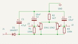
    >>21518355 I have to admit my mistake and admit Kris8888 is right, because I added an unupdated schematic where the capacitors in the grid supply are not present, and in my project they are!!! I found a schematic of a pcb made in kicad and you can see that they are there and in the picture you can see them too (I need to go to the eye doctor :) . I have now made a fix with an additional capacitor having a person mass to the star and the touchdown has reduced! just as I thought it would. Unfortunately only reduced, but it is audible when you are very close to the speakers. this may be due to the fact that when working with silicon diodes there is better filtering than in the "gz34" mode, because before it hits the capacitor in the mosfet gate the voltage goes through a voltage divider (which is supposed to lower the voltage at the mosfet source to the voltage prevailing at the gz34 output when "working". I have no other idea :) .

    i add a picture of the grid 1 power supply


    A schematic of a power supply with capacitors and resistors, showing labeled component values. .
  • #29 21521169
    Jap
    Level 29  
    Congratulations! I was also drawn to the tube... I have committed 4 audio projects on a tube.... unfortunately the biggest and most expensive one, despite having been in operation for 10 years .... is not brought to a beautiful visual state. It cost a lot of money but the pleasure of building it and even more of listening to it - unforgettable. You motivated me to finish the cabinet....
  • #30 21521222
    pawlik118
    Level 33  
    Committed or done?

    Folks, this mistake is made so often now that it is impossible to eradicate it in a moment.
    If one has done something good - we say "I did" (a thing, an action).
    If one has done something bad - we say "I have committed" (a mistake, a sin)

Topic summary

A DIY tube amplifier project based on 6P6S, ECC82, and EF86 tubes evolved over four years from an intended Ampex 2012 clone to a custom design due to issues with input pentode gain and power output. The builder addressed hum problems by implementing a star ground topology and replacing a choke with a capacitance multiplier. Output transformers from P. Ogonowski were used in a push-pull configuration. The amplifier features a minimalist front panel with visible screws and 3D-printed transformer covers made from PET-G material, chosen for heat resistance up to 80°C. The design includes a fixed bias phase inverter circuit, which sparked discussion about potential risks of tube aging and distortion. The input selector switch is located on the rear for aesthetic reasons. Component choices such as the negative feedback resistor and volume potentiometer were discussed, with suggestions to use quality parts like an Alps 50k potentiometer. The project also touched on tube equivalences and differences, clarifying that PCC88 and ECC88 tubes share characteristics except for heater parameters. The community exchanged advice on circuit improvements, transformer impedance matching for PCL805 tubes, and practical construction tips. The thread concluded with encouragement for DIY tube amplifier building and a focus on enjoying the process and sound quality.
Summary generated by the language model.
ADVERTISEMENT