logo elektroda
logo elektroda
X
logo elektroda

Creating a Tube Amplifier with 2xPCL86, EM84 Indicators and Transformers TG2.5-1-666 & TS40/29/670

23949 35
ADVERTISEMENT
Treść została przetłumaczona polish » english Zobacz oryginalną wersję tematu
  • #1 7894440
    Anonymous
    Anonymous  
  • ADVERTISEMENT
  • #2 7894531
    Futrzaczek
    VIP Meritorious for electroda.pl
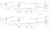
    The scheme is fine. In addition to a few details that I always talk about in the Bambino scheme: 100k in anode triodes and 22-100nF as a coupling. Otherwise it will sound like a telephone.

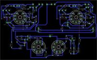
    The tile, however, is not properly designed. There is no one thick mass rail. You mix high-current (high-ripple) sections with low-current ones. They should be separated or connected so that at the very end there are connections through which the smallest current flows: input, leakage resistors.
  • #4 7894867
    Anonymous
    Anonymous  
  • #5 7895979
    Futrzaczek
    VIP Meritorious for electroda.pl
    Slide the electrolytic capacitors away from the power tubes. 47uF in the power supply will not be satisfied with such conditions.
  • #6 7898681
    Anonymous
    Anonymous  
  • #7 7898937
    thereminator
    Conditionally unlocked
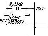
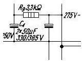
    You're right, there's no dot. Without it, a minus of the right capacitor is connected to the minus of the power supply, and the whole mass of the amplifier hangs in the air - the system would not work. Probably the error results from the fact that in the original system a double capacitor was used, having one common negative lead for both capacities, and at the same time a metal enclosure connected to the minus, then connecting the minus outlet with the downside of the power supply, and the rest of the elements would be connected to it through the housing capacitor screwed to the chassis.
  • #8 7899893
    Futrzaczek
    VIP Meritorious for electroda.pl
    1) Too thin mass path. It would be good to "extinguish" the middle peg of the stand.
    2) I am not advised to drive anything under the 47uF capacitor. The paths are too close.
    3) Why are you afraid of stretching some resistors? - such as 100k. Such a tangle of paths by the lamp may not please her.

    Be assured that the first tile may be suitable just to the basket.
  • #9 7900749
    painlust
    Guitar amplifiers specialist
    Be assured that not only the first but also the next 5 will be in the trash ...
  • #10 7902704
    sabringer
    Level 25  
    If you are not afraid of 'wasting' some laminate, I can give you my (untested!) Layout for PLC86. (How I find it ;)
    I do not have the equipment to etch the tiles myself, but if I have already ordered it (costs) I am convinced that it will work.

    I would like to break the common opinion that it is not possible to do a working ;) tile right away. But unfortunately I do not have any materials ...
  • ADVERTISEMENT
  • #11 7902730
    thereminator
    Conditionally unlocked
    Alternatively, if you really want to make an amplifier on the board, you can buy ready-made PCBs (PCL (ECL) 82 or 86, depending on soldering the jumpers] from Traxman (on the auction) and you have problems with designing and digesting.
  • ADVERTISEMENT
  • #12 7907087
    Anonymous
    Anonymous  
  • #13 7908614
    sabringer
    Level 25  
    I was just about to ask - do you want to have a glow on the tile? I would give them separate cables on the bottom of the chassis, and to the plate at right angles.

    And do you have any preferences regarding the setting of lamps? Mainly it is about which way the eye is to be turned. I have a laid out layout for such an amplifier (I just have to make it in some reasonable way, because my working notes hardly anyone will understand ;) ), EM84 can be rotated in it in quite wide limits.
    And the anode triode resistor asks to give it from the bottom of the stand, directly on pins 3 and 9.
  • #14 7908731
    Anonymous
    Anonymous  
  • #15 7921340
    Anonymous
    Anonymous  
  • #16 7921510
    Futrzaczek
    VIP Meritorious for electroda.pl
    It will disturb you.
    First of all, the whole mass loop will be made. The system may start to whistle, wheeze and go crazy for no particular reason.
    Second, it will be easy to get a raise.

    It looks quite reasonable. Try it.
  • #17 7925981
    irekr
    VIP Meritorious for electroda.pl
    Mass loops are one of the basic problems of any tube amplifiers.
    And my remarks from my own experiences from 40 years ago:
    1. ECL / PCL 86 lamps were most often mounted horizontally, facilitating heat dissipation. In addition, the lamps were oriented in the own axis in such a way that the bars of the net tensioners were in the vertical plane. This prevented the mesh from gluing in case of overloading.
    2. In addition to the change proposed by the moderator in the scope of capacitance of the coupling capacitor, I will provide as part of my own changes that I made in this amplifier 40 years ago:
    - C1 and C3 capacitors changed to 22 nF stryrofelx 600V;
    - C2 capacitor changed to 0.1 styroflex 160V microfarad
    - I removed the capacitor C4 (cathode electrolyte) - it is not needed and the removal greatly improves the sound of the amplifier with slightly reduced sensitivity of the amplifier (about 5 dB), which is easily compensated by a larger control;
    - C5 and C6 capacitors increased to 100 microfarads;

    Watch out for the voltage resistance of the drive indicator system capacitors - resistors R10, R11, capacitor C7. On the pentode anode, the DC voltage is as much as the supply voltage, while the variable component can reach a value of even about 100V. In case of overloading, the voltage may be higher than the supply voltage (the transformer acts as an ignition coil in the car) and I would be scared to install capacitors with a working voltage of less than 1 kV.
    I wish you perseverance and success. This old amplifier was constructed in the 1950s and despite its simplicity is really very good considering the small amount of elements.
    I used it myself for over a dozen years and I remember its excellent sound.
  • #18 8025473
    Anonymous
    Anonymous  
  • #19 8180513
    Anonymous
    Anonymous  
  • ADVERTISEMENT
  • #20 8181234
    Futrzaczek
    VIP Meritorious for electroda.pl
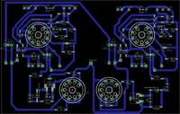
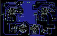
    The tile on the left will create a beautiful whistle - a mass loop created by the filled areas.

    I would be more inclined to the right picture if it were not for a few things that I told you earlier.
    - the path of the mass is definitely too narrow, it can even be thickened with a wire if only the expansion was not enough. In addition, it creates a closed loop, which is unacceptable.
    - you have an unconnected central peg. Even if you do not have it in the stand, it's worth to make a dot out of it.
    - capacitor C2 / 100uF / will be unhappy with the working conditions, move it away.
    - make signal paths narrower, it will be harder for them to catch interference.
    - 220k in the circumference of the triode anode I would give a one- or two-watt.
    - this system will whistle and chatter if the entrance hangs in the air. Try to connect some empetrojka or zworzyj R2 / 470k / for the duration of the trial.
    - under C1 / 47nF / you have a strange clove.
    - mix the mass of the power supply, pentodes and triodes. Ripples are transmitted through the ground bus and cause excitation. The closer to the entrance, the more "low-voltage" circuits you should have. If you can not distinguish it on the board, make it a thick wire.
  • #21 8185951
    Anonymous
    Anonymous  
  • #22 8186147
    sabringer
    Level 25  
    It probably meant that they are like 3 "blocks", each has its own local mass, which combine into one general. In the diagram you have shown the mass run of the rail - these "steps" separate the masses of individual steps and show the order of connection.
  • #23 8186809
    Futrzaczek
    VIP Meritorious for electroda.pl
    Creating a Tube Amplifier with 2xPCL86, EM84 Indicators and Transformers TG2.5-1-666 & TS40/29/670
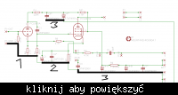
    I let myself brutally treat this scheme with paint.

    1 - tiny ripple at the very end of the chain.
    2 - greater ripple, in the middle of the chain
    3 - high ripple at 100 Hz frequency, as close as possible to the bridge rectifier, so that they do not move along the rest of the system.

    Now it is understandable?
  • #24 8187307
    Anonymous
    Anonymous  
  • #25 8196628
    Anonymous
    Anonymous  
  • #26 8196973
    sabringer
    Level 25  
    The question is whether it is a logarithmic potentiometer. How did you connect it?
    Separating capacitor at the input is (unfortunately) a necessity - there is a "leakage" of a constant component from some of today's signal sources.

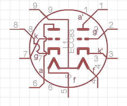
    However, I have no idea why you put the ECL86 lamp in place for PCL86 - after all it is a completely different glow. (unless you changed them in the meantime, then I turn back the honor) If there is a short circuit on the filament, the lamp unfortunately is suitable for the basket.
  • #27 8198266
    Anonymous
    Anonymous  
  • #28 8198991
    AnTech
    Level 31  
    The letter C was used for determining potentiometers with exponential characteristics.
    To adjust the volume you need a potentiometer marked with the letter B (logarithmic) if it is produced by Telpod or A (audio) if it is imported.
  • #29 8199015
    sabringer
    Level 25  
    1. Ok, I have not worked with old telepods (?) And I do not know ;) signs. But check it will not hurt, because there are still "logarithmic" potentiometers - just like "right and left".
    Edition: Oh, I was right that something did not suit me ;)
    2. :) . Cool, I've seen so many schemes that I always ask ;) .

    3. Well, very well - unfortunately, the ECL86 is no longer suitable for use (or you can measure its glow current to see why it fell) I put on a short circuit on the filament - it works a bit mechanically when switching on and warming up.

    Regulation - It depends on what it looks like in the assembled system. The standard topology is a potentiometer at the signal input.
    For example, as in MV3 (I happen to have myself) at EF86 http://www.fonar.com.pl/audio/schematy/inne/wzm_mv3.gif " target="_blank" rel="nofollow noopener ugc" class="postlink inline" title="" > http://www.fonar.com.pl/audio/schematy/inne/wzm_mv3.gif
    The values of the elements are irrelevant, I mean topology. At 1M and 470k in S1 triode, the question of choosing the value of the capacitor (so that it does not cut the bass, but without exaggeration with the value) I shoot at max. 100n.
  • #30 8202506
    AnTech
    Level 31  
    Did you measure whether it is 50Hz or 100Hz?
    The 50 Hz sound comes from the glowing circuit of the tubes and it is difficult to fight it. The location of transformers is also very important. Axes of the network transformer and loudspeaker cores can not be concurrent, and their proper arrangement can be assessed by hearing.
    The 100 Hz hum is due to the flow of the lamp supply current through the output transformer. The constant voltage of the charged power supply contains a certain 100 Hz variable component (if I used a full wave rectifier) and you hear this pulsation in the loudspeaker. To reduce it, use larger filtering capacities in the anode voltage supply.

    As for the amplifier to be excited, try to change the output of the ear and ground signal on the secondary winding of the loudspeaker transformers.
    This 47nF capacitor, buttoned on the potentiometer, changes the transmission characteristics of the entire audio track, it should not be at all.

Topic summary

The discussion revolves around the design and construction of a tube amplifier using PCL86 tubes, EM84 indicators, and specific transformers (TG2.5-1-666 and TS40/29/670). The original poster faced challenges with the filament supply voltage, needing 13.3V for the PCL86 while only having 6.3V available. Suggestions included using a voltage doubler or an additional transformer. Participants provided feedback on circuit design, emphasizing the importance of proper grounding, capacitor placement, and avoiding mass loops to prevent noise. Various corrections to the schematic and layout were proposed, including adjustments to capacitor values and the arrangement of components to enhance performance. The final design was reported to function well, with plans for further refinements and a completed amplifier showcase.
Summary generated by the language model.
ADVERTISEMENT