logo elektroda
logo elektroda
X
logo elektroda

Welding machine Cemont s 1601 BluMaste - fixing three elements

gibalohio 16052 24
ADVERTISEMENT
Treść została przetłumaczona polish » english Zobacz oryginalną wersję tematu
  • #1 8197296
    gibalohio
    Level 15  
    Hello.
    I received a Cemont S 1601 BluMaster welding machine for repair.
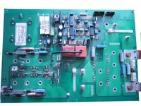
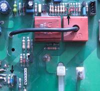
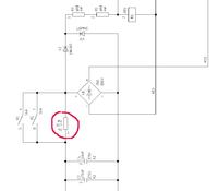
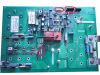
    I need to identify 3 elements because the previous "professional" did not replace the transistors with their inefficient soldering, they exchanged what you can see, two more LEDs and replaced some element on the power board with wire. After which he left it.
    I am asking for help in determining which elements should be in the selected places, because I am not sure if these elements are correct values?

    Welding machine Cemont s 1601 BluMaste - fixing three elements Welding machine Cemont s 1601 BluMaste - fixing three elements Welding machine Cemont s 1601 BluMaste - fixing three elements
  • ADVERTISEMENT
  • Helpful post
    #2 8197624
    Drake160
    Level 17  
    In place of the green cable you need to give a resistor, I do not remember the exact value but when you give ok 12 ohm / 5W it should be fine, this resistor is damaged as there is a short in the power block or there is something wrong with the relay that should resistor shortly after switching on. As for this blue diode, you have just one above it so you can see how it sits there, probably it is a Zener diode at 18V. The diode above this red current transformer (the one with four of them the same) is a common rectifier diode - 1n4148 will be good.
  • #3 8197703
    gibalohio
    Level 15  
    So, yes, the peezer is good, the transistors are replaced only once again I will have to solder them because I fear to look. Diodes as you say agree. I entered the sign in the goggles and jumped out what you wrote or 18V 1 W and the other is a simple rectifier. There is one mentioned diode similar to the transistor, it also had to be burned but it is next to the second one and the system is similar, so I assumed that it is also correct. Besides, I measured all the diodes and transistors on the disc, it would seem that everything is fine. Please, hint if something else could have been damaged?
  • #4 8197783
    Krzyś33
    Level 25  
    Hello. Buddy did not write what are the symptoms of damage, and you asked only for the type of elements indicated by you. How would anyone know about other damage if you did not write about the symptoms? And do not assume that the diode next in a similar arrangement is the same, because they may be responsible for the lower and the current limitation of current and they will be different. Greetings.
  • #5 8197901
    gibalohio
    Level 15  
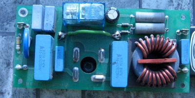
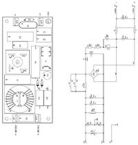
    As I wrote earlier, I got it in this state tz: rozkręcane and I do not want to connect it because I know that if something is broken, transistors will go faster than they were founded. So please, suggest what else I should check that the attempt to connect did not end immediately with the need for their next exchange. As far as I know, the welding machine burned once, after which it was quickly repaired (I suspect that the cable was soldered to it) then there was a bang and the welding machine again landed in the workshop and that's it. Dude set about the exchange, but I guess he did not advise soldering, as you can see in the pictures, and he left it that way. I also found a schematic of this PCB with this cable

    Welding machine Cemont s 1601 BluMaste - fixing three elements

    Welding machine Cemont s 1601 BluMaste - fixing three elements

    From this it would appear that the current limiting resistor should have 47R 9W or do I think well?
  • ADVERTISEMENT
  • Helpful post
    #6 8197965
    Krzyś33
    Level 25  
    You think well. But check with the meter after connecting in series with the 100W bulb network (after disconnecting the rest of the circuits on the N bridge and P bridge terminals) the voltage at these terminals.
  • ADVERTISEMENT
  • #7 8198045
    gibalohio
    Level 15  
    And what tension should I expect there? Of course, after connecting this light bulb. I will do it tomorrow at work so I want to learn as much as possible.
  • Helpful post
    #8 8198183
    Krzyś33
    Level 25  
    No load about 300-350V (best check in the diagram - if you have access). Write tomorrow (I will also tell you about 17) about the effects. I'll be happy to help you.
  • #9 8198221
    gibalohio
    Level 15  
    Ok, thanks for your help, I'm going to work tomorrow and I think I will let :D know what and how.
  • #10 8198607
    Drake160
    Level 17  
    As for this resistor, I suggested the construction of another (similar) welding machine and this resistor had 12 ohms. If there is such a possibility, it would be possible to disconnect the power block as described by colleague Krzyś33, so that only the low-voltage part works and catch the oscilloscope waveforms at transistor gates. Some welders have voltage control and then there will be no waveforms, but this one does not look too advanced :)
  • #11 8200595
    gibalohio
    Level 15  
    So, yes, I connected this resistor and connected it to the power supply and at the output showed me a voltage of 320 V. I found that it is good, so I connected the rest of the system and switched it on. The LED on the front panel lights up, the fan has started, the capacitors have charged and the diode has gone out. The fan goes on with the 320V voltage, nothing burns but there is no voltage on the terminals. After turning off and waiting until the capacitors are discharged and reconnected, the story repeats itself. I wonder if I miss something because three free slots have been left on the album. Unfortunately, I can not find a schematic and I do not know what to connect, or there should be anything connected at all.

       Welding machine Cemont s 1601 BluMaste - fixing three elements
  • ADVERTISEMENT
  • Helpful post
    #12 8201047
    Drake160
    Level 17  
    What is the layout of the "power block" of the power block? Usually there is some sg3525 or similar. I suggest you start analyzing the plate from this merger because it does not seem to have control runs at all.
  • #13 8201139
    gibalohio
    Level 15  
    I found a diagram of a similar plate, this black connector is used there for the plate which I do not have, so it probably should not be connected. As for the rest, probably not because I do not see anything missing. As for scalak, I do not know because I have this welder at work, I will look tomorrow, but since you claim that it can be from this I can replace them all because I have only three of them. Well, unless you are programmed?
  • Helpful post
    #14 8201244
    Drake160
    Level 17  
    I'm not saying that it's the winemaker's fault but there are a lot of things that can block it. These scalps are quite easy to pick up so it's a good point of hookup. Do you have an oscilloscope?
  • #15 8201535
    gibalohio
    Level 15  
    Unfortunately not. I do not have an oscilloscope or have a place to borrow from. :-( . What could block them? there are not many items on the disc. Maybe I can do it on foot? Just ask for a hint what to look for?
  • #16 8203583
    gibalohio
    Level 15  
    Well, yes, I have replaced all three scales SG3525A, LM 339N, LM 249N and nothing has changed. The welder is in the same condition as before the exchange, i.e. it starts and then the diode on the front panel goes out and that's it. The fans go but the current on the terminals is not there all the time. What else should I check?
  • Helpful post
    #17 8204044
    Drake160
    Level 17  
    Without an oscilloscope, it will not be easy. What you can measure with a voltmeter is the voltage on some legs sg3525: on the 16th leg should be 5V, on 10 - 0V, on 8 above 2.5V. More rather, it will not be measured. If, for example, it turns out that 8 is 0V, then you need to look from where to find the signal. From what I remember, this foot is used to connect the temperature sensor on the heat sink.
  • #18 8204133
    gibalohio
    Level 15  
    I have 3 heat sinks and only one sensor on one of them. One sensor that enters from the winding. Let two sensors have a transition. On the other two radiators you can see the thread as if on sensors, but there is no sign that they were screwed there, so I will measure this scalpel on this 8th leg and see. Of course, I will also measure. If there is no voltage, you may suspect that they were supposed to be there. It would be a good idea to use the layout of this CD, but I can not find it anywhere. Or a picture of the middle. Unfortunately, I do not know if these two white sockets on the disc (picture above) were not connected to each other, or just to those missing sensors. I will try tomorrow, I will look for possible paths and let me know tomorrow. For now, thanks.
  • #19 8207841
    gibalohio
    Level 15  
    I have measured this and on the 8th leg I have 4.25V at 10 0V and at 16 at 7 V. I think everything plays. In addition, I had other tensions the biggest I had it 14V and the smallest 1.2V I do not remember on which legs. It seems that the system is working properly. Thanks for the hints, but I probably will not be able to fix it, especially since I do not have either an oscilloscope or a schematic. Of course I am very stubborn and I will look for myself further. If you have any recent suggestions, what else can I check write here.
  • #20 8208157
    Krzyś33
    Level 25  
    Hello. Unfortunately, without the oscilloscope it will be harder. It would be useful to check if you have rectangular pulses on the side of the primary and secondary separating transformer and whether they are correct, and you will not check this without an oscilloscope, because the swapping of control transistors and power does not make sense and may expose you to high costs, but I wish you good luck.
  • #21 8208200
    Drake160
    Level 17  
    I still have one idea :) In some Kemppi brand welding machines on the primary side of the separating stick are inserted LEDs. When waveforms are present, the diodes are on. Maybe I am exaggerating a bit with this combination but with the diode insertion there is not much work and maybe it will help.
  • #22 8211272
    gibalohio
    Level 15  
    Thanks to everyone for the hints, tomorrow I will look again Monday and of course I will use your advice. If something moves I will let you know the damage of your time. No schematic, oscilloscope what can be done. I simply refused because no one was able to fix it and I always thought that everything can be repaired only the will is needed. If it does not go normally it remains extrema :D or, or, but I do not want to brag to the forum because it is not professional. Thanks again and best regards.
  • #23 8211956
    Drake160
    Level 17  
    I found a manual for this machine. There is no detailed schematic, but at the end there is a block diagram, which shows what should be on the slots and there are some pictures of the interior. Maybe it will be useful for something.
  • #24 9359695
    gibalohio
    Level 15  
    Hello, unfortunately I was unable to repair this welder. Is there anyone in this forum for whom I can entrust the repair of this welder? I cover shipping and mailing costs as well as repair costs. I am asking only for info how much this repair can cost. greetings
  • #25 9686276
    gibalohio
    Level 15  
    Subject to be closed. It's not up to date.

Topic summary

The discussion revolves around the repair of a Cemont S 1601 BluMaster welding machine, focusing on identifying and replacing three critical components that were improperly handled by a previous technician. The user seeks assistance in determining the correct values for a resistor, a Zener diode, and a rectifier diode. Various responses suggest specific resistor values (12 ohms / 5W and 47 ohms / 9W) and diode types (Zener diode at 18V and 1N4148 rectifier diode). The user also describes symptoms of the machine's failure, including a lack of output voltage despite the machine powering on and the fan operating. Suggestions include checking voltages at specific transistor legs and the possibility of using an oscilloscope for further diagnostics. Ultimately, the user expresses frustration at being unable to repair the machine and seeks professional help.
Summary generated by the language model.
ADVERTISEMENT