logo elektroda
logo elektroda
X
logo elektroda

Repairing Damaged PCB on CEMONT S1600 Welding Inverter: Missing Components

idepopizze 17787 17
ADVERTISEMENT
Treść została przetłumaczona polish » english Zobacz oryginalną wersję tematu
  • #1 13187048
    idepopizze
    Level 33  
    Hello.
    The welder was standing in the garage and something heavy fell on it.
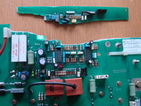
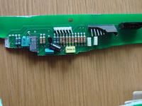
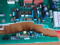
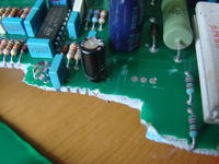
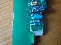
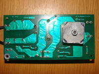
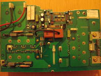
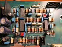
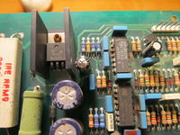
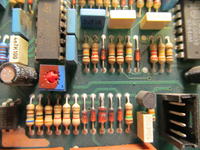
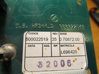
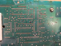
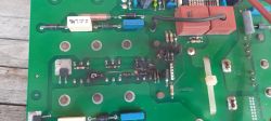
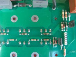
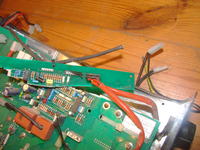
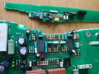
    A printed circuit board is broken. There are also a few elements missing. I have not found the scheme for it although there are some similar solutions. Below photos.
    Repairing Damaged PCB on CEMONT S1600 Welding Inverter: Missing Components Repairing Damaged PCB on CEMONT S1600 Welding Inverter: Missing Components Repairing Damaged PCB on CEMONT S1600 Welding Inverter: Missing Components Repairing Damaged PCB on CEMONT S1600 Welding Inverter: Missing Components Repairing Damaged PCB on CEMONT S1600 Welding Inverter: Missing Components Repairing Damaged PCB on CEMONT S1600 Welding Inverter: Missing Components Repairing Damaged PCB on CEMONT S1600 Welding Inverter: Missing Components

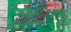
    As you can see, the LM339N is broken, the TL431C is damaged, some resistors are removed and some element together with the heat sink. Most likely, the voltage stabilizer - although I have not yet traced the diagram on the PCB so it's safe.
    Would a good soul with this welder or scheme help me with the missing elements:
    1. Missing stabilizer or power transistor.
    2. Two missing resistors next to the broken LM339N. I also suspect that they will be some precise resistors.
    3 Missing item over LM339N - most likely a capacitor because there was only one wire on the leg.
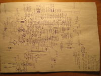
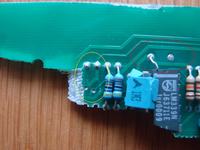
    Here, in colorful ellipses, places after them
    Repairing Damaged PCB on CEMONT S1600 Welding Inverter: Missing Components

    Will this welder require the oscilloscope to be started after inserting the missing elements? I have not dealt with the SG3525 so far, hence my doubts
  • ADVERTISEMENT
  • #2 13188538
    bestler
    Admin of DIY, Automation
    Could you take a picture of the whole album? Or maybe the front panel? It seems to me based on the above that I probably never had such a welder.
  • ADVERTISEMENT
  • #3 13188861
    idepopizze
    Level 33  
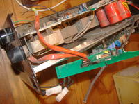
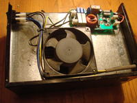
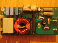
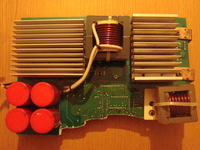
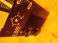
    Whole:
      Repairing Damaged PCB on CEMONT S1600 Welding Inverter: Missing Components Repairing Damaged PCB on CEMONT S1600 Welding Inverter: Missing Components

    Rectifier block:
    Repairing Damaged PCB on CEMONT S1600 Welding Inverter: Missing Components Repairing Damaged PCB on CEMONT S1600 Welding Inverter: Missing Components Repairing Damaged PCB on CEMONT S1600 Welding Inverter: Missing Components

    The rectifier bridge on the side wall has the inscription:
    Facon BJ39 933

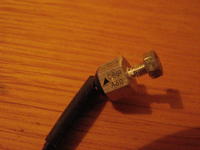
    Sensor on the main rectifier bridge heatsink:
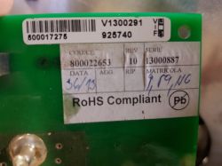
    Repairing Damaged PCB on CEMONT S1600 Welding Inverter: Missing Components

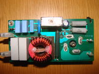
    Motherboard:
    Repairing Damaged PCB on CEMONT S1600 Welding Inverter: Missing Components Repairing Damaged PCB on CEMONT S1600 Welding Inverter: Missing Components

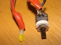
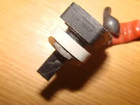
    In addition, there is also a potentiometer from the front panel and LED

    Repairing Damaged PCB on CEMONT S1600 Welding Inverter: Missing Components

    If it's more accurate, I can give you something more.
  • ADVERTISEMENT
  • #4 13207517
    IREK21A
    Level 10  
    Hello. I am a novice on the electrode - please be understanding. I will help with this electronics, I have two such PCB IGBT R2747 damaged in the device CEMONT TH 1600 and EUROTRONIC TIG 1501 (DCI) electronics the same plus HF, control from the front panel. I have a schematic pcb in the latest generation with a microcontroller.
  • #5 13209225
    idepopizze
    Level 33  
    Thank you very much for your answer.
    I have found operating instructions for this welder. However, there is only a block diagram.
    Link

    A little bit like electronics is in this welding machine:
    esquemas puma sx 35131
    Link

    This EUROTRONIC TIG 1501 (DCI) will probably be something like:
    Link
    or
    Link
    I have not checked yet whether the operational amplifiers work the same as in S16000

    If I can, I would ask for a clear photo of the LM339N system and the surrounding elements.
    There should be missing 4 elements that were lost after breaking the plate.
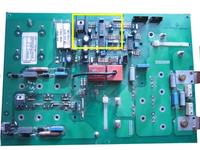
    In the example photo of the whole CD I have marked the fragment in the yellow frame.

      Repairing Damaged PCB on CEMONT S1600 Welding Inverter: Missing Components

    The biggest problem I have with missing 2 resistors
    If there were any problems with uploading photos or files, please let me know.
  • #6 13210109
    bestler
    Admin of DIY, Automation
    Very similar electronics are also in the MAHE i-200 welding machine. Unfortunately, there are slight differences, especially in the upper part, which the author needs.
  • #7 13215851
    IREK21A
    Level 10  
    I have a problem how to send a photo PCB
  • #10 13216196
    idepopizze
    Level 33  
    Thank you very much for your help. Now I will have resistors and dispelled doubts.
    By the way, at first glance, this dark electronic capacitor next to 7815 is strangely swollen.
    I do not close the subject yet, because maybe the welding machine will not start right away (which I would not want, of course)
  • #11 13236208
    IREK21A
    Level 10  
    Hi. This condenser over LM339N is 100nf / 63V. I put a drawing on the knee (photo) not fit with the photo PCB earlier. What some will laugh!?. Repairing Damaged PCB on CEMONT S1600 Welding Inverter: Missing Components
  • #12 13257143
    idepopizze
    Level 33  
    Because I was asked for a bit more information about this welder about it:

    The front panel potentiometer has no additional elements mounted on it. What may give such an impression is a plastic mass. The middle leg is in the shirt. As you can see on the photo, the potentiometer is 10k and, according to my measurements, has a linear characteristic.

      Repairing Damaged PCB on CEMONT S1600 Welding Inverter: Missing Components Repairing Damaged PCB on CEMONT S1600 Welding Inverter: Missing Components

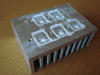
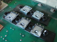
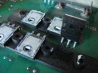
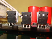
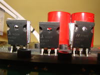
    The output circuit is on five such transistors:
      Repairing Damaged PCB on CEMONT S1600 Welding Inverter: Missing Components Repairing Damaged PCB on CEMONT S1600 Welding Inverter: Missing Components Repairing Damaged PCB on CEMONT S1600 Welding Inverter: Missing Components

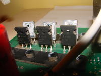
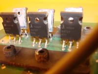
    Transistors of the input circuit: (internal side)
      Repairing Damaged PCB on CEMONT S1600 Welding Inverter: Missing Components Repairing Damaged PCB on CEMONT S1600 Welding Inverter: Missing Components

    (outer side)
      Repairing Damaged PCB on CEMONT S1600 Welding Inverter: Missing Components Repairing Damaged PCB on CEMONT S1600 Welding Inverter: Missing Components

    I do not have a torque wrench to check the tightening torque (the force with which the bolts are screwed), but in all three radiators the screws were tightened loosely. I do not know if this is due to the operation of the system (heating-cooling of the heat sink) or whether it is the factory setting.

    IREK21A Is a 1.58k-1 resistor % next to the stabilizer 7815 was read from the barcode or was it measured?

    Added after 3 [hours] 53 [minutes]: < br />

     Edition:
    I have looked at the Puma's SX35131 diagram and these "five output transistors" are double RURG3020 diodes.
  • #13 13277578
    IREK21A
    Level 10  
    Hello. The absence caused by damage to the router. The "idepopizze" elements were measured in the system. I checked today the resistor next to LM 7815 desoldered is 3.3k-1% next next to 10k-5% and the other two are 4.7k-1% .Z my photo is really hard to read! What is I surprised to see that they are loose!? As for professional equipment, the distance from PE is a frivolous solution. In the Polish ENEL 150 power transistors screwed to the radiator! In my cemont th 1600 probably this was the cause of the power level damage because one central igbt r4727 fired. The deformed laminate is known to have a temperature.
  • #14 13277822
    idepopizze
    Level 33  
    All screws on all heat sinks seemed to be screwed by hand (manually, that is, more tightly with fingers). When I finish it, it's more solid.

    I had doubts about this 1.58k, because the colors did not match very well. 10k next to the colors looked ok. Probably soon I will throw here the scheme of this CD when I finish the patch.
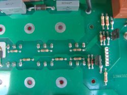
    Buying the original R4727 igbt can be a problem.
  • #15 19858424
    lfcfan_lfc
    Level 1  
    Hi everyone. My brother managed to get an Oerlikon / Citoarc 1600i
    It switches on, but it makes a whistling sound, like an ultrasound when turning up the potentiometer of current. He opened it and could not see any defective part, nor any burnt part/area. He tried to weld but there seems to be no current coming out, only small sparks.
    Any idea on where he should look on the boards?
    Thanks,

    Dodano po 1 [minuty]:

    Repairing Damaged PCB on CEMONT S1600 Welding Inverter: Missing Components
  • #16 20020724
    wakycampa
    Level 2  
    Hello, I have the same equipment and I need the values ​​of the 7 resistors at the bottom left of the diagram, the ones next to the triac bd138 Repairing Damaged PCB on CEMONT S1600 Welding Inverter: Missing Components, I think they are the only ones missing. In my computer they have all been burned and I cannot know the value. Thank you so much [quote="IREK21A"]Hi. This condenser over LM339N is 100nf / 63V. I put a drawing on the knee (photo) not fit with the photo PCB earlier. What some will laugh!?. Repairing Damaged PCB on CEMONT S1600 Welding Inverter: Missing Components [/quote] Repairing Damaged PCB on CEMONT S1600 Welding Inverter: Missing Components
  • ADVERTISEMENT
  • #17 20027715
    idepopizze
    Level 33  
    It should help


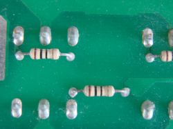
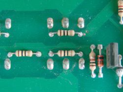
    Repairing Damaged PCB on CEMONT S1600 Welding Inverter: Missing Components Repairing Damaged PCB on CEMONT S1600 Welding Inverter: Missing Components Repairing Damaged PCB on CEMONT S1600 Welding Inverter: Missing Components Repairing Damaged PCB on CEMONT S1600 Welding Inverter: Missing Components
  • #18 20029644
    wakycampa
    Level 2  
    thank you very much for your help. Now I'm going to buy all the components. although on my board the 6 transistors are different than those in your photos. mine are 12n60a4 but I suppose they will be equivalent to the R4727 that your board mounts.

    Repairing Damaged PCB on CEMONT S1600 Welding Inverter: Missing Components

Topic summary

The discussion revolves around repairing a damaged PCB from a CEMONT S1600 welding inverter after it was struck by a heavy object. The user reports missing components, including an LM339N and a TL431C, along with several resistors. Various users provide assistance by sharing links to similar schematics, offering insights into the components, and discussing the potential for using parts from other models like the CEMONT TH 1600 and EUROTRONIC TIG 1501. The conversation includes requests for photos of specific components and measurements of resistors, as well as troubleshooting advice for related issues in similar welding machines. Users also discuss the importance of ensuring proper connections and the potential need for replacement parts.
Summary generated by the language model.
ADVERTISEMENT