logo elektroda
logo elektroda
X
logo elektroda

Kemppi Minarc Evo 150 Stuck at 12-13 Amps After Replacing 60APU04 and MP930

aleccc 4353 10
Best answers LABEL_AI_GENERATED

How can I fix a Kemppi Minarc Evo 150 that is stuck at 12–13 A after replacing the 60APU04 and MP930 parts?

The most likely fault is in the IGBT module, not the PFC stage: check the gate waveforms with an oscilloscope and compare the resistance between the gates, then desolder the module and test it with a tester if the readings differ [#20830282] If the IGBT module checks out, move on to the gate drivers [#20830282] The PFC module is probably working, and with it fitted the capacitor voltage should be about 385 V DC [#20888891]
AI summary based on the discussion. May contain errors.
ADVERTISEMENT
  • #1 20828847
    aleccc
    Level 3  
    Posts: 8
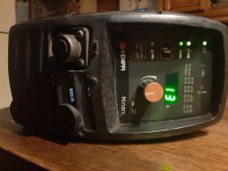
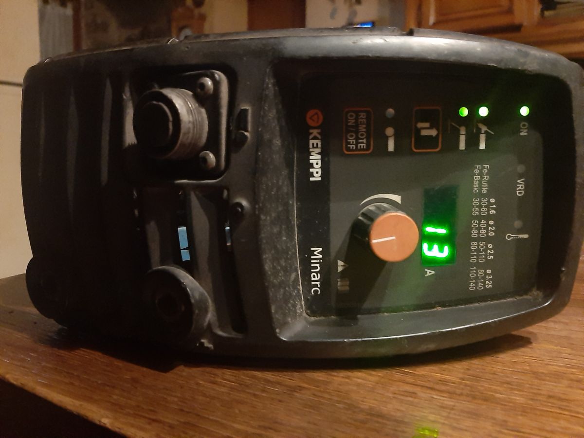
    hello, I need a little help with a kemppi minarc evo 150 (stuck on 13 amps)
    I specify that the equipment had fallen (cutting the five 60APU04 and mp930 3.30)all were replaced
    thank you all Close-up of the control panel of a Kemppi Minarc Evo 150 welder with the current setting at 13 A.
  • ADVERTISEMENT
  • Request for ideas after confirming all supply voltages are normal

    #2 20829712
    aleccc
    Level 3  
    Posts: 8
    hello, after some tests (SERVICE MANUAL
    Minarc Evo 150/180), everything seems correct to me:
    tp5 tp4 dc link: 395vdc
    c56: 15.16vdc
    c26 v62: 15.86vdc
    v62 v46: 25.4 vdc
    n3 r22: 12.52vdc
    the voltages on the a001 card are good too

    if anyone has an idea?

    Added after 3 [minutes]:

    hello, after some tests (SERVICE MANUAL
    Minarc Evo 150/180), everything seems correct to me:
    tp5 tp4 dc link: 395vdc
    c56: 15.16vdc
    c26 v62: 15.86vdc
    v62 v46: 25.4 vdc
    n3 r22: 12.52vdc
    the voltages on the a001 card are good too

    if anyone has an idea?
    I use Google translate to make myself understood
  • ADVERTISEMENT
  • #3 20830282
    smd
    Welding machines specialist
    Posts: 542
    Help: 98
    Rate: 249
    Probably a damaged IGBT module. Check the waveforms on the gates with an oscilloscope, you can also measure the resistance - if it differs between the gates, you would need to desolder the module and check it with a tester. If it is OK, then you need to check the gate drivers.
  • #4 20831285
    aleccc
    Level 3  
    Posts: 8
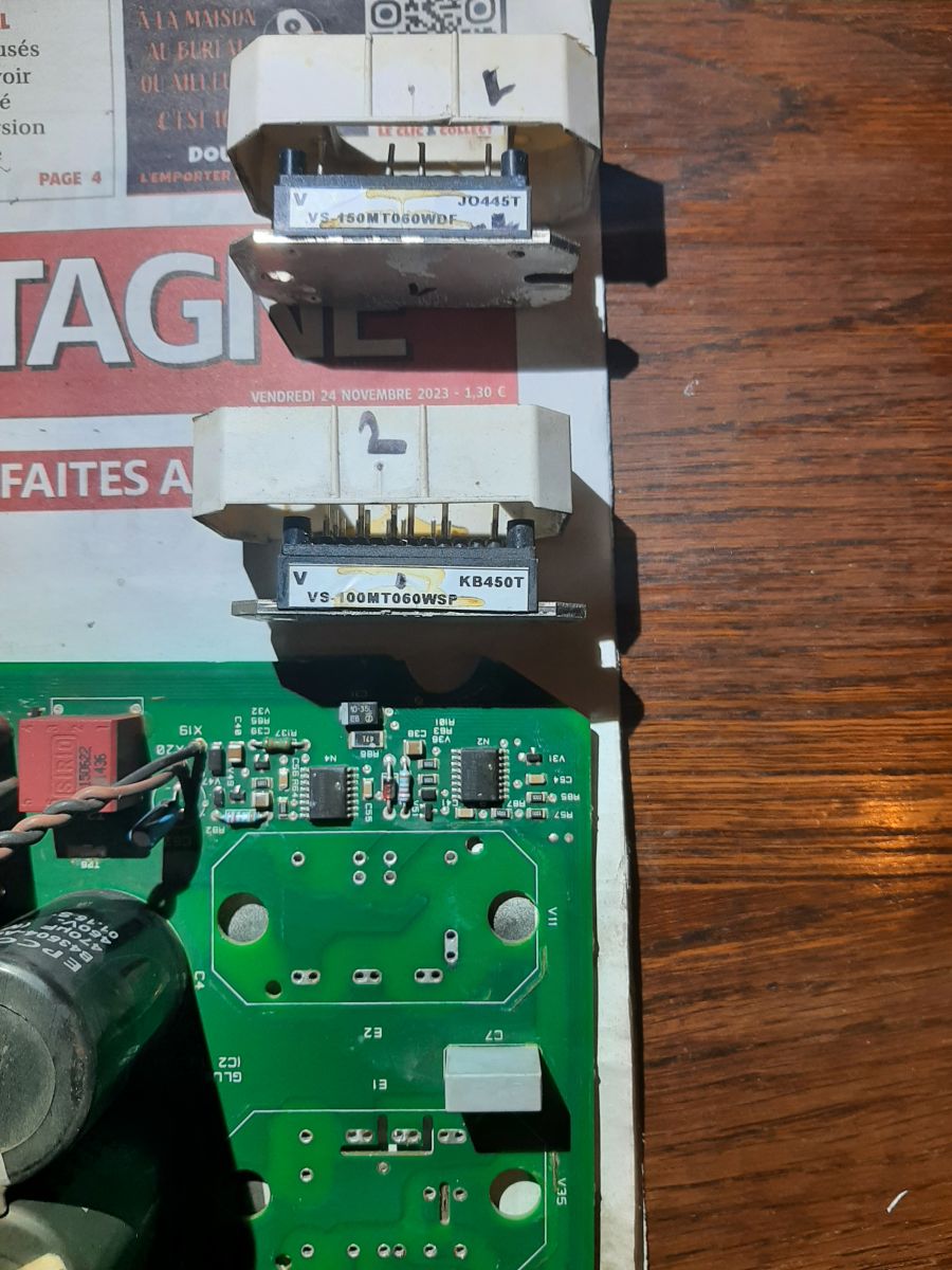
    I was also thinking about a module but my level in electronics is quite average, however I am an excellent desolder (I removed the two modules) here are the references: vs-150mt060wdf and vs-100mt060wsp
    Is there an easy way to check your parts?
    They seem complicated to find in stores! Two electronic modules VS-150MT060WDF and VS-100MT060WSP next to a printed circuit board.
  • #5 20833917
    aleccc
    Level 3  
    Posts: 8
    Hello, both modules are out of service, where can we buy parts? THANKS
  • ADVERTISEMENT
  • #6 20861087
    aleccc
    Level 3  
    Posts: 8
    hello, the igbt modules cannot be found, and it is possible to rebuild them (partially or completely) all the diodes are good (only the igbts are not good, they are not in short circuit)
    what component choices would be best suited? igbt and diodes, thank you
  • ADVERTISEMENT
  • #8 20888891
    smd
    Welding machines specialist
    Posts: 542
    Help: 98
    Rate: 249
    In my opinion, the PFC module is 99% functional. I didn`t write to desolder it, I wrote for you to desolder the IGBT module and check the waveforms on the gates. Why do you need a module if you haven`t checked anything? By the way, when you insert the PFC module, check the voltage on the capacitors, it should be about 385V DC.
  • #9 20972136
    marcislusis
    Level 1  
    Posts: 1
    Does anybody have a clue - I can adjust Amp to 150 with knob, but when welding, power goes down to ~50AMP. Any ideas?
    Regards!
  • #10 20972961
    smd
    Welding machines specialist
    Posts: 542
    Help: 98
    Rate: 249
    Check the primary current control elements of the main transformer.

Topic summary

LABEL_AI_GENERATED
Discussion about a Kemppi Minarc Evo 150 inverter welder stuck at about 12–13 A after a fall and replacement of damaged 60APU04 and MP930 parts. Supply and control voltages were checked against the service manual and appeared normal, including the DC link and A001 board rails. The main suspicion shifted to a faulty IGBT power module; advice was given to inspect gate waveforms with an oscilloscope, compare gate resistances, and test the module out of circuit if needed. The user later identified two removed power modules, VS-150MT060WDF and VS-100MT060WSP, asked how to verify them, and reported that both modules were defective and difficult to source. Later replies suggested checking the control potentiometer, confirming PFC capacitor voltage around 385 VDC, and inspecting the primary current control elements of the main transformer when welding power drops under load.
AI summary based on the discussion. May contain errors.
ADVERTISEMENT