logo elektroda
logo elektroda
X
logo elektroda

Drawing a Single Line Diagram for Energy Company Connection Approval

blumberg 66468 20
ADVERTISEMENT
Treść została przetłumaczona polish » english Zobacz oryginalną wersję tematu
  • #1 8259208
    blumberg
    Level 11  
    Hello colleagues, I am asking for help in drawing a single-line diagram, as required by the energy company. Below I present a connection drawing from which a single-line diagram would be drawn.
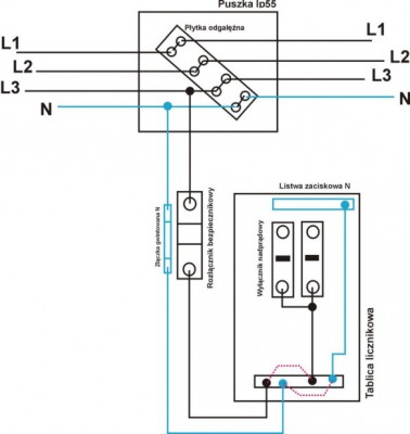
    Drawing a Single Line Diagram for Energy Company Connection Approval
  • ADVERTISEMENT
  • #2 8259737
    zdzisiek1979
    Level 39  
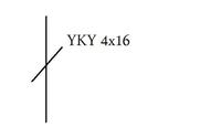
    The only thing that comes to my mind buddy from this drawing is something like that.
    Drawing a Single Line Diagram for Energy Company Connection Approval
  • #3 8260004
    Arturo2005
    Level 33  
    Rather, without this "bypass" at the fuse :)
  • #4 8260190
    blumberg
    Level 11  
    Without which workarounds ?? at the disconnector ?? can a colleague draw correctly ?? Do you need to put element descriptions? e.g. fuse "S" 20A ??

    The sentence starts with a capital letter. Please correct. [retrofood]
  • #6 8260634
    blumberg
    Level 11  
    Ok, thank you ,,, And tell me, colleagues, would you have to draw such a diagram on the application to the energy company ?? Will such a scheme be accepted by the power plant and will not "purr" anything ??? :-)
    And I also have a question, should the voltage values be given in V or kV ?? The conditions for connection include the following provisions: the network operates in the following system: a) MV - with the neutral point earthed through a resistor and b) 0.4kV - TN-C ... and further writes: measurement and billing system at 0.23kV, single-phase direct. ... Do we give the values in the single-line diagram in V or kV ???
  • #7 8260688
    brief99
    Level 22  
    I always write the voltages they give in "conditions", if they gave them in MV, I would write them in MV, as they say in kV, write them in kV, but let smarter colleagues say something.
  • ADVERTISEMENT
  • #8 8260845
    trebuch1
    Level 26  
    The diagonal line indicates the number of phases, not the number of wires.

    Crap of the year.
  • #9 8260875
    blumberg
    Level 11  
    So if there are two diagonal lines, it means that it is badly drawn?

    I asked to improve the spelling of the previous post. Point 6 of the Regulations. [retrofood]
  • ADVERTISEMENT
  • #10 8260914
    brief99
    Level 22  
    trebuch1 wrote:
    The diagonal line indicates the number of phases, not the number of wires.

    Nonsense...

    Drawing a Single Line Diagram for Energy Company Connection Approval
  • #11 8261105
    zdzisiek1979
    Level 39  
    One dash can be used and a description in the form of a digit corresponding to the number of wires in the cable, additionally the cable type, number of wires and wire cross-section must be indicated.
    The diagram itself must additionally have a description of the protection devices, type and value, it must also be the type of network it is and any markings of the network to which the connection is made.
    Drawing a Single Line Diagram for Energy Company Connection Approval
  • #12 8261117
    remik_l
    Level 29  
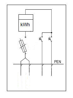
    I propose something like this at this point (create the appropriate values):

    Drawing a Single Line Diagram for Energy Company Connection Approval

    What about the protective or protective neutral conductor?
    What kind of network do you have, is it TT?
    How far is this connector from the powered building / buildings?

    As for the lines, I suggest you read this .
  • #13 8261130
    brief99
    Level 22  
    A colleague of Blumberg described a few posts above, incl. what kind of network is this ... TN-C, so we have grounded N ...
  • #14 8261151
    remik_l
    Level 29  
    brief99 wrote:
    A colleague of Blumberg described a few posts above, incl. what kind of network is this ... TN-C, so we have grounded N ...


    Sorry, I didn't read it.

    So we have PEN on the power supply and now, depending on whether it is close to the building / buildings, we divide it into the ZKP or not.
  • #15 8261164
    brief99
    Level 22  
    Ok ... The colleague did not write about the division of PEN into PE and N, but about drawing a single-line diagram to the attached drawing (I presume that the drawing shows the connection of devices that my colleague blumberg made.
  • #16 8261623
    trebuch1
    Level 26  
    Thank you for correcting my pointless speech immediately.
  • ADVERTISEMENT
  • #17 8261768
    zdzisiek1979
    Level 39  
    It looks like an installation in some older building, this junction box somewhere in the corridor :D maybe there was a renovation or a rental and you need to connect the electricity and conclude a new contract.
  • #18 8262004
    blumberg
    Level 11  
    I would like to thank my colleagues for the information provided so far. The installation is in garages (20 pieces in a row), boxes are in each garage, so far we had a flat rate for light, but the energy company asked to apply for connection conditions. There is an aluminum cable connection between the garages (4 wires - two black, one brown and one blue). And this is what it looks like.
  • #19 8263213
    brief99
    Level 22  
    remik_l wrote:
    I am proposing something like this at this point
    Drawing a Single Line Diagram for Energy Company Connection Approval


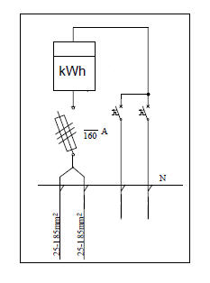
    Well, not quite, my friend Remik_l, you drew a three-phase disconnector, and my colleague blumberg has a single-phase disconnector (at least this is how my colleague blumberg is shown in the drawing) :-) And not "N" but "PEN" ... Well, by the way.
  • #20 8264158
    remik_l
    Level 29  
    Now it should match the data provided by the author.

    Drawing a Single Line Diagram for Energy Company Connection Approval

    However, I believe that this is not a correct solution to this problem, only a temporary one.

    Are these meters to be in garages, and circuit breakers to protect the circuits in them?
    If so, you should split the PEN cable and replace the installation in garages with a 3-wire one, because you will not get 10 mm?Cu for lighting / sockets. It would be even better if this aluminum cable was replaced with a 5-wire one.
    You should apply an RCD in the socket circuits.
  • #21 8264184
    brief99
    Level 22  
    Well, I can see that my friend is trying ... It is best to let the author of the post write what he has in the conditions ,,, RCD in the garage ?? I wonder what my friend will do there ??

Topic summary

The discussion revolves around creating a single-line diagram required by an energy company, based on a provided connection drawing. Participants share various interpretations and suggestions for the diagram, emphasizing the importance of including element descriptions, voltage values, and network types. Key points include the need for clarity in representing phases and wires, the necessity of indicating protection devices, and the correct labeling of voltage in either V or kV based on the energy company's specifications. The conversation also touches on the specifics of the installation, including the use of aluminum cables and the configuration of circuit breakers and RCDs in garages.
Summary generated by the language model.
ADVERTISEMENT