logo elektroda
logo elektroda
X
logo elektroda

House switchgear overview drawing: Review & improve DIY electrical scribble (cross-sections)

kemid 19746 5
ADVERTISEMENT
Treść została przetłumaczona polish » english Zobacz oryginalną wersję tematu
  • #1 17271404
    kemid
    Level 10  
    Hello everyone,

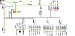
    Please, watch my scribbles - is it suitable for something? I am not an electrician by profession, but I tried to arrange it myself. Reading many topics, I noticed that the electrode has a strange manner. Rather not change it in style, just such a delicate or less delicious. I am asking for hints on what to change, what to add and what to throw away. Regards
    House switchgear overview drawing: Review & improve DIY electrical scribble (cross-sections)

    Wire cross sections

    circuits:

    1 - 5 x 2.5 mm2
    2 - 5 x 2.5 mm2
    3 - 5 x 2.5 mm2
    4 - 3 x 1.5 mm2
    5 - 3 x 2.5 mm2
    6 - 3 x 2.5 mm2
    7 - 3 x 2.5 mm2
    8 - 3 x 2.5 mm2
    9 - 3 x 2.5 mm2
    10 - 3 x 1.5 mm2
    11 - 3 x 2.5 mm2
    12 - 3 x 2.5 mm2
    13 - 3 x 2.5 mm2
    14 - 3 x 2.5 mm2
    15 - 3 x 2.5 mm2
    16 - 3 x 2.5 mm2
    17 - 3 x 2.5 mm2
    18 - 3 x 2.5 mm2
    19 - 3 x 2.5 mm2
    20 - 3 x 1.5 mm2
    21 - 3 x 1.5 mm2
    22 - 3 x 1.5 mm2
    23 - 3 x 1.5 mm2
    24 - 3 x 1.5 mm2
    25 - 3 x 1.5 mm2

    Garage, tin can - I wonder if there should be 3 phases there at all. For what ?. I will probably add one 1-phase circuit on a separate differential and it will stay that way.

    The 11 kW connection may be small, but it will stay for now. If in practice it turns out that too little power will be increased. Regards
  • ADVERTISEMENT
  • #2 17271453
    kozi966
    Moderator of Electricians group
    Did a colleague familiarize themselves with this topic:
    https://www.elektroda.pl/rtvforum/topic3263074.html?

    And with this:
    https://www.elektroda.pl/rtvforum/topic3419770.html?
    And in particular with this:
    Quote:
    1. When submitting a problem, be sure to send all available information.

    This is information such as:
    a) Network system (available in the connection agreement - connection technical conditions) - available: TT, TN, IT;
    b) Value and type of protections (for example: gG 16A fuse, B10A circuit breaker);
    c) Type of power cables and number of cores (for example: aluminum / copper, three-core / two-core).
    d) Technical documentation (for example: installation design, diagrams, DTRs and others).
    This will facilitate conversation and streamline the problem verification process. Of course, not all of these data correspond to every topic and it is not always easy to find, so if you are unsure whether they fit the topic, it's worth writing them. If in the topic users indicate the lack of important information, it must be completed.
  • ADVERTISEMENT
  • #3 17271710
    kemid
    Level 10  
    Hello,

    pre-meter security:

    House switchgear overview drawing: Review & improve DIY electrical scribble (cross-sections)

    System of 0.4 kV TN-C power supply network operation

    From the meter to the switchboard at home 4 x10 mm2 (copper) - 36 m

    Moderated By Łukasz-O:

    The unnecessary part of the post has been deleted.

  • ADVERTISEMENT
  • #4 17271837
    kozi966
    Moderator of Electricians group
    kemid wrote:
    pre-meter security

    Ask ZE to change the type of security.
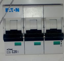
    20A (in addition the installation switch with C character) will cause a problem of the lack of selectivity of the tripping of the protection.

    At the beginning I warn that such a drawing, in private, reads terribly.
    1. Why does the heat pump "hang" on the RCD?
    2. Why does the induction hob hang on the RCD?
    3. What sections are covered with the switchgear?
    4. Why lighting and garden sockets "hang" on one protection?
    5. What is the characteristics of residual current devices used in the installation?

    By the way, I suggest not to mention comparisons about digging in the ground, gardening, smoked meats and other unrelated to the topic.
    This is an electrical topic, and its solutions and implementation are also subject to Polish law. An electrician in Poland must show appropriate certificates and, if you want to design, also construction permits. And so far no colleague has asked about it yet. The comments of a colleague retrofood are absolutely justified, because the electrical installation is designed based on a wider range of information than just the appearance of the switchgear itself and the apparatus contained in it.
  • ADVERTISEMENT
  • #5 17272288
    kemid
    Level 10  
    kozi966

    with this drawing I understand you perfectly. You are a man from the industry and this is just gibberish for you, but the reality of the beloved Poland is such and not different. Everyone plows as much as he can. He has been building a house for several years and I have done many things with him myself. I have sketched this drawing to make it easier to understand certain things and to make it easier to ask.
    With this induction, you see how I mentioned above, people ask for help, and it happens differently. I know what's going on and why you need to (change your device permanently) to change it. I will change to without a differential. Same with the pump. The pump is a song of the future, but an approach would be good if it were.
    The switchgear is not yet "trimmed" because it is only being created virtually ...
    I thought that since these are external circuits and only two, why should not they be on one differential. The sockets will be used only in winter for Christmas lights. In total, there are already 25 circuits. I didn't want to increase it yet

    Moderated By Łukasz-O:

    The unnecessary part of the post has been deleted.

  • #6 17273255
    Łukasz-O
    Admin of electroenergetics
    In this section, we do not deal with installation design. We can check the project and indicate the basic errors that were indicated.
    I close the thread.
ADVERTISEMENT