logo elektroda
logo elektroda
X
logo elektroda

Single-line diagram of a single-phase electrical installation

qbart_gt 28254 7
ADVERTISEMENT
Treść została przetłumaczona polish » english Zobacz oryginalną wersję tematu
  • #1 15723297
    qbart_gt
    Level 11  
    Hello everyone

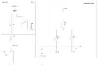
    I`m trying to understand the single-line diagram. I have a request to check the diagram I have drawn, which is to be sent to ZE. This is a single-phase installation on the plot. Generally, I am asking for advice on whether my scheme makes sense :)


    Single-line diagram of a single-phase electrical installation
  • ADVERTISEMENT
  • #2 15723318
    kozi966
    Moderator of Electricians group
    qbart_gt wrote:
    Does my scheme make sense?

    NO.

    From the beginning:
    qbart_gt wrote:
    This is a single-phase installation on the plot


    I see the counter 3f.
    You mark the connections with dots and the PEN hangs in the air or on the ground.
    Are you moving from where? from the earth electrode? PE too? This is what it looks like from this diagram.
    No information about the network system from ZE.
    Is a 3m pin supposed to guarantee a transfer resistance of less than 10 ohms? Any data for such a statement (soil resistivity)?

    Why is there a ban in ZK? 160A and pre-meter bills. is unmarked? Why pre-meter is a circuit breaker? (there will probably be a lack of selectivity).
  • ADVERTISEMENT
  • #3 15723320
    elpapiotr
    Electrician specialist
    - Single-phase power supply and output via a 3-phase meter?
    - No pre-meter security value
    - What kind of 160 A fuse switch is this?
    - No cross-sections and lengths of power lines provided.
    - No kWh localization and input protection.
    - Switching to single-phase power supply again (probably the facility`s switchgear)?
    - What is the function of the switch? automatic 1P 20 A ?
    - Where is the lighting circuit?

    The rest was provided by my colleague kozi966.
  • ADVERTISEMENT
  • #4 15724437
    qbart_gt
    Level 11  
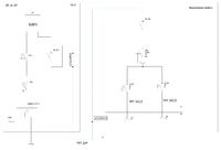
    I made corrections. Now the drawing looks like this: Single-line diagram of a single-phase electrical installation

    The network system from ZE is TN-C. I corrected the value of the fuse switch in the connector, which is actually 40A. This is the RBK00 disconnector. The pre-meter protection is 13A and has C characteristic. There are no lighting circuits because there is no gazebo on the plot, and only two sockets are needed.

    In the drawing, the facility`s switchgear was supposed to be FR301, not FR303
  • #5 15724565
    haneb
    Level 24  
    Some strange extension of the PEN bus in ZK to the switchgear, no cable connection to it (e.g. introduced only on FR).
    No information about the type of cables and cross-section.
  • ADVERTISEMENT
  • #6 15724719
    Łukasz-O
    Admin of electroenergetics
    What is the point of B16 security measures if there is C13 in front of the counter?
  • #7 15724737
    qbart_gt
    Level 11  
    Łukasz-O wrote:
    What is the point of B16 security measures if there is C13 in front of the counter?


    Yes, I know it doesn`t make any sense. I didn`t make the switchboards. Just trying to make a diagram.


    Another version of my diagram:

    Single-line diagram of a single-phase electrical installation

    I don`t know if it draws the dividing point correctly. I will be grateful for any comments.
  • #8 15725472
    haneb
    Level 24  
    The minimum cross-section of PEN is 10mm² Cu and 16mm² Al, so a 2x4mm² cable is an error.
    Such a division in the switchgear would cause the residual current circuit breaker to trip.

    For me it`s more or less like this:
    Single-line diagram of a single-phase electrical installation

Topic summary

The discussion revolves around the evaluation of a single-line diagram for a single-phase electrical installation. The original diagram faced criticism for various issues, including the use of a three-phase meter, lack of pre-meter security values, and insufficient details on cable types and cross-sections. The author made corrections, clarifying that the network system is TN-C and adjusting the fuse switch value to 40A. Further feedback highlighted errors in cable specifications and the need for proper circuit protection. The author sought additional comments on a revised diagram, emphasizing the importance of correct PEN bus connections and appropriate cable sizes.
Summary generated by the language model.
ADVERTISEMENT