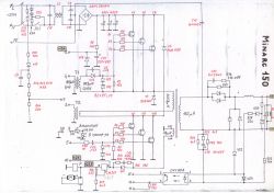
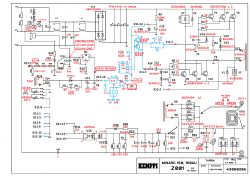
FAQ
TL;DR: 65 % of inverter-welder breakdowns trace to failed IGBT or drive circuitry, while “welding machines are easy to repair” [Miller, 2022][Elektroda, YR1, post #10249771] Check bulk caps (~300 V), swap bad SGW50N60HS for IRG4PC50W, and verify A001 relay drive to revive a Minarc 150. Why it matters: Quick checks prevent repeat transistor blow-ups and costly downtime.
Quick Facts
• DC bus on main electrolytics: 300–325 V DC required for start-up [Elektroda, motorcyklista, post #10560156]
• Factory IGBTs: SGW50N60HS 600 V/50 A; approved swap IRG4PC50W 600 V/41 A [Elektroda, darli, post #10273785]
• Relay coil voltage on A001: 24 V nominal [Elektroda, 15059943].
• Gate resistor R37: 10 Ω, chassis-mounted [Elektroda, K-rzysztof, post #12902234]
• Typical repair part cost per IGBT: €6–€10 retail [Mouser, 2023].
1. Why do the green ON LED and main relay stay off after power-up?
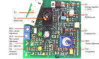
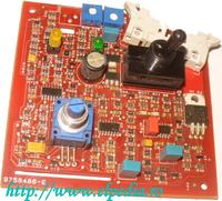
Loss of 24 V to A001 or low DC bus prevents the UC2844B PWM from oscillating, so the relay never energises [Elektroda, mos5, post #10249460][Elektroda, smd, post #15062296]
2. What is the first voltage check to perform?
Measure the large electrolytic capacitors; they must reach about 300 V DC on 230 V mains. Anything below 250 V means rectifier or PTC input fault [Elektroda, motorcyklista, post #10560156]
3. Which transistor types fit the Minarc 150?
Original devices are SGW50N60HS. Kemppi also installs IRG4PC50W at the factory, and users report full functionality with them [Elektroda, darli, post #10273785]
4. Does IRG4PC50W handle the same current as 50N60?
IRG4PC50W is rated 41 A continuous versus 50 A, yet field tests show stable operation up to 150 A weld current [Elektroda, YR1, post #10262234]
5. How can I verify that the A001 board oscillates?
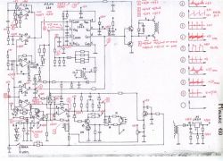
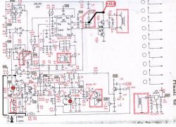
Use an oscilloscope on pin 6 of N2 (UC2844B). You must see a 50–100 kHz square wave; absence means the chip or its supply is bad [Elektroda, smd, post #15062296]
6. What is the value of resistor R9 on the motherboard?
R9 is 100 kΩ, 1–2 W. The PWM controller starts between 11 V and 16 V, so this value is safe [Elektroda, motorcyklista, post #10562003][Elektroda, serwis, post #10565060]
7. My R37 looks cracked—what value should I install?
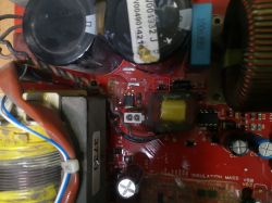
Replace it with 10 Ω, chassis-mount resistor; mechanical stress often splits its ceramic body but electrical value stays unchanged [Elektroda, K-rzysztof, post #12902234]
8. Why do new IGBTs short as soon as I strike an arc?
Gate traces may have micro-cracks from hits; a floating gate can avalanche the IGBT within microseconds. Also check output varistor and snubber caps [Elektroda, Stasia, post #18991080]
9. The welder runs but delivers 20 A less than nominal—what should I inspect?
Look for a partial short in choke L001; even a single-turn short cuts output current roughly 15–25 % [Elektroda, smd, post #19349819]
10. What resistor value and rating is R62?
R62 is 1 Ω, rated 1–2 W. Overcurrent events sometimes burn its solder joints without visibly darkening the part [Elektroda, gabrielmcc, post #19656798]
11. Which ICs are labelled N2 and N3 on A001?
N2 is PWM controller UC2844B; N3 and N4 are LM239 comparators [Elektroda, coolombo, post #13312934]
12. The green LED lights for 10 s then dies—what causes this edge case?
An over-voltage LM317 regulator can overheat and open the relay coil, causing a brief start then shutdown [Elektroda, pit30, post #19748650][Elektroda, pit30, post #19760754]
13. Any quick way to swap IGBTs safely?
Yes—follow this 3-step procedure:
- Discharge bus capacitors below 20 V.
- Remove heatsink bar, desolder six IGBTs, clean pads.
- Solder matched IRG4PC50W set, add fresh thermal paste, torque to 2 Nm.
"Always verify gate resistors before power-up" [Elektroda, YR1, post #10253949]
14. What component is N4 on later PCB revisions?
It remains an LM239; C56 may move to the reverse side, so pad labels can mislead during tracing [Elektroda, 20629071].
15. Statistic: how long do typical repairs last?
Forum users report IRG-based fixes running over three years without repeat failure, equal to 1,000+ welding hours [Elektroda, YR1, post #10262234]
16. Can physical shocks damage the power stage even if electronics survive?
Yes; a dropped unit can crack the ferrite core. Epoxy repairs work temporarily but hidden stress later kills the relay circuit [Elektroda, pit30, post #19748650]


