logo elektroda
logo elektroda
X
logo elektroda

Transformer Diagram for 080-56632-01, Class B Viking B-2, E210832: 2x6V, 1x16V Configuration in UPS

Piotr59mb 32172 6
ADVERTISEMENT
Treść została przetłumaczona polish » english Zobacz oryginalną wersję tematu
  • #1 11205952
    Piotr59mb
    Level 19  
    Hello.
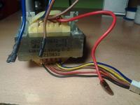
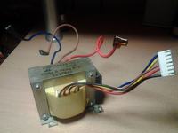
    I am trying to find a transformer diagram somewhere where it is:
    080-56632-01
    0452
    Class B Viking B-2
    E210832

    The transformer comes from an uninterruptible power supply. Somewhere, I read that it has 2x6V and 1x16V. (I can connect 6V windings in series so as to have 12 and simultaneously connect with a 16V winding between the 6V windings connected in series so as to have 16V + 6V?)
    Transformer Diagram for 080-56632-01, Class B Viking B-2, E210832: 2x6V, 1x16V Configuration in UPS Transformer Diagram for 080-56632-01, Class B Viking B-2, E210832: 2x6V, 1x16V Configuration in UPS
  • ADVERTISEMENT
  • Helpful post
    #2 11206048
    mickpr
    Level 39  
    First draw the windings, measure the resistance, check the wire thickness if possible.
    Then there will be time to connect.
    You can connect the windings in series as you wrote, if you remember about the current efficiency of such a construction and do not exceed it.
    For safety during operation, use fuses. :)
  • ADVERTISEMENT
  • #3 11206135
    Piotr59mb
    Level 19  
    I am not worried about current efficiency, because with 12V the maximum 0.8A will go (alarm siren and radio receiver) and from 24V approximately 200mA (photocells).
    Actually, I am primarily interested in the primary winding, I assume it is a blue and brown wire, but I do not know which side ... (on both sides are)
    From the top (where there are 3 wires):
    blue - brown - 0.7 ohms
    blue - red - 0.7 ohms
    brown - red - 0.7 ohms (maybe 2x 6V?)

    From the bottom (5 wires)
    black - yellow - 8.9 ohms
    black - blue - 8.4 ohms
    red - brown - 1.4 ohms
    yellow - blue - 1.2 ohms


    Diameters of wires:
    From the top:
    Blue - 2.2 mm
    Brown - 2.2 mm
    Red - 2.2 mm

    From the bottom :
    Black - 0.5 mm
    Red - 0.5 mm
    Brown - 0.5 mm
    Yellow - 1 mm
    Blue (here at the wire there are 2 wires) - 0.5 and 1 mm
  • Helpful post
    #4 11206200
    Anonymous
    Level 1  
  • ADVERTISEMENT
  • #5 11206239
    Piotr59mb
    Level 19  
    blue - brown - 0.3 ohms
    blue - red - 0.3 ohms
    brown - red - 0.2 ohms (I do not know how the results differ from now on)
  • ADVERTISEMENT
  • Helpful post
    #6 11206244
    mickpr
    Level 39  
    With such resistances, no wonder.
  • #7 11207797
    Piotr59mb
    Level 19  
    marekzi wrote:
    Probably windings 8,4ohm and 8,9ohm are network (two sections for 115V and 230V networks) - connect in series, pay attention to connect the windings in phase. Connect to the network through a light bulb (ordinary) about 60W / 230V.

    black - yellow - 8.9 ohms
    black - blue - 8.4 omh
    How to connect in a row? From this comes out that the yellow to the tap in the middle of the winding, right? Black and blue for the winding for which 230V goes, and for this in a row a light bulb, I understood correctly?

    Edit.
    I connected blue and black to the network.
    At the top (3 wires) I have 2x 8.4V
    At the bottom (5 wires) between red and brown I have 20.8V (after straightening and conquering capacitors I should have 27V. Now the question is how to "do" 12V (preferably without a stabilizer)

    Edit2.
    I found another transformer, also from UPC.
    It features:
    Winding with tap - 22.5V and 45V
    Winding without tap - 22.5V
    Winding with tapping - 8.5V and 17V

    Which one to choose to get the values closest to 12V and 24V DC?

    Edit3. The photocells are AC / DC and operate calmly at 22.5 AC. The only thing left now is to figure out how to get 12V

    Edit4. After straightening I have 15V. Can I break these 3V by connecting, for example, 4 diodes in series? Or one LED?

    Edit ... 5. 8.5V - bridge - capacitor 4700uF and works.

    Thanks for all the help :wink:

Topic summary

The discussion revolves around the transformer diagram for the model 080-56632-01, specifically for the Class B Viking B-2 UPS. The user seeks guidance on connecting the transformer windings, which include configurations of 2x6V and 1x16V. Participants suggest measuring resistance and wire thickness before connecting the windings in series, ensuring proper phase alignment. The user provides detailed resistance measurements for various wire combinations, indicating potential configurations for both primary and secondary windings. There is a focus on achieving desired output voltages (12V and 24V) without using a voltage stabilizer, with discussions on alternative transformers and their specifications.
Summary generated by the language model.
ADVERTISEMENT