Hello, I know that the topic has been discussed many times, but somehow it does not appeal to me.
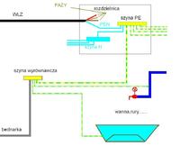
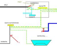
Namely, what should the GSW bus connection look like? Let's assume that we have a four-wire WLZ led to the RG, where the separation (on the PE bus) PEN to PE and N is connected to the PE bus, sockets are connected to the PE rail, and then we pull the (thick) wire from the PE bus to the GSW located e.g. in the basement to which we connect metal pipes, taps, bathtubs, boiler ... and the GSW itself is connected to the hoop iron which is screwed to the foundation earth electrode. I understand it well? Should it look like the picture shows?
Namely, what should the GSW bus connection look like? Let's assume that we have a four-wire WLZ led to the RG, where the separation (on the PE bus) PEN to PE and N is connected to the PE bus, sockets are connected to the PE rail, and then we pull the (thick) wire from the PE bus to the GSW located e.g. in the basement to which we connect metal pipes, taps, bathtubs, boiler ... and the GSW itself is connected to the hoop iron which is screwed to the foundation earth electrode. I understand it well? Should it look like the picture shows?


