logo elektroda
logo elektroda
X
logo elektroda

MAX038 Generator Issue: MAX442 Replacement or Alternative for 1Hz-30MHz Circuit

milik 12111 8
ADVERTISEMENT
Treść została przetłumaczona polish » english Zobacz oryginalną wersję tematu
  • #1 1411964
    milik
    Level 23  
    Hello

    I have a problem with MAX038 - I wanted to put together a generator 1Hz-30 M Hz but I do not know what to do with this MAX442. Can I not give it there or replace it with something else and it is there? What do you think about this ?

    MAX038 Generator Issue: MAX442 Replacement or Alternative for 1Hz-30MHz Circuit
  • ADVERTISEMENT
  • #2 1412016
    c2h5oh
    Moderator
    Hey !

    milik wrote:
    Hello

    I have a problem with MAX038 - I wanted to put together a generator 1Hz-30Hz but I do not know what to do with this MAX442. Can I not give it there or replace it with something else and it is there? What do you think about it?


    MAX442 is a two-channel amplifier operating up to 140 MHz. Used in VID MUX / AMP applications. Thus, it serves to amplify the signal and adjust the voltage levels.

    In addition, it is a pity to waste the MAX038 capabilities to build a generator working in such a narrow frequency range (1Hz-30Hz). You could do a multivibrator on several transistors.
  • #3 1412109
    milik
    Level 23  
    But the stain I wrote Hz instead of MHz was supposed to be 1Hz – 30MHz – I'm sorry :oops: . From what I found, MAX443 costs 100PLN :( so it's completely out. As for the possibilities, at the beginning I wanted to make a generator that would be able to work as a wobbler, but nowhere did I find such a scheme so I stayed at the generator itself.
  • ADVERTISEMENT
  • #4 1412141
    c2h5oh
    Moderator
    Hey !

    :)
     Can you use transistors? (broadband amplifier) In total, you only need to amplify the signal from the circuit and create a buffer.
    Without the buffer at the output, the MAX behaves quite strangely. The cables for the range switch are very important. They can not be too long. Ideally, the switch is soldered directly on the generator board and has short paths.
  • #5 1414970
    qantas
    Level 12  
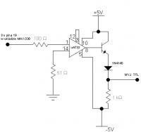
    I used mA733 in this circuit
     to the frequency meter I connect only by resistance 47om.
    powodenia.
  • #6 1415835
    PJS
    Level 15  
    I used MAX4381 - but you have to convert the PCB and the R12 resistor to 10k, because (at least I was getting an amplifier). Maxim sends a free sample of this system (but in the smd version). Oh, I did not make the generator up to 30MHz, because I do not need that much, but max4381 has a band of 210MHz, so it should work.
  • ADVERTISEMENT
  • #7 1421049
    milik
    Level 23  
    Qantas could you tell me how you did it with including A733? Because it is a bit different from the usual operational increase and I'm afraid that I will do something wrong.
  • ADVERTISEMENT
  • #8 1423043
    qantas
    Level 12  
    ok but tomorrow because only tomorrow I go to work and there are diagrams. I do not have a scanner but I'll sort it out somehow.
    so far.
  • #9 1427189
    qantas
    Level 12  
    Hello and sorry for the lapse.
    below I put a circuit diagram which I have used in my generator. I adapted this system from the pulse formation system of some frequency meter, but unfortunately I do not remember the publication.
    As a transistor in my system there is BFY90, but I suspect that I will go with everyone else.

    Best wishes and good luck.

Topic summary

The discussion revolves around issues with the MAX038 generator, specifically regarding the use of the MAX442 component. The original poster seeks alternatives or replacements for the MAX442 in a circuit designed to generate frequencies from 1Hz to 30MHz. Responses suggest that the MAX442, a two-channel amplifier, is not ideal for this application, and alternatives like transistors or other components such as the MAX4381 and mA733 are proposed. Users emphasize the importance of proper circuit design, including the need for a buffer and short connections to avoid signal distortion. Circuit diagrams and modifications for using different components are also discussed.
Summary generated by the language model.
ADVERTISEMENT