Elektroda.com
Elektroda.com
X

Voltage regulator for the generator

żałosna udręka 6420 19
This content has been translated flag-pl » flag-en View the original version here.
  • Voltage regulator for the generator
    I did not find a voltage regulator on Mosfet N. Maybe the factory ones are in this technology, but they are usually sealed and you can't look. One thing is certain, these are one of the most emergency components in aggregates. The one I cobbled together should be more resilient.
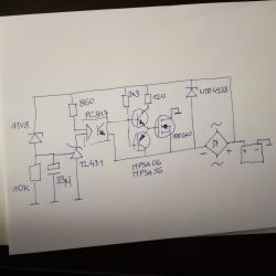
    A description of the action.
    The voltage divider is on the zener diode to reduce the quiescent current draw. The diode is theoretically 12 V, but I easily selected one for 11.8 V. The capacitor reduces the switching frequency. The TL431 switches at 2.5 V. If we add with a zener diode, it comes out to 14.3 V. This voltage is optimal. The optocoupler separates the other side of the circuit. Motorola transistors amplify the current. Transil 33 V at the end protects the Optocoupler and has what to do. The no-load winding generates 20 V.
    I put the bridge at 100V.
    Summary.
    The system is deliberately built with a minimum number of elements. It was supposed to fit in the original housing with a heat sink, on a universal board. I milled the original content because it was well glued.
    If I screwed something up, I'm reluctant to know about it. However, the system is still working.

    Cool? Ranking DIY
    About Author
    żałosna udręka
    Level 34  
    Offline 
    żałosna udręka wrote 2328 posts with rating 897, helped 184 times. Live in city Warszawa. Been with us since 2012 year.
  • #2
    Mlody_Zdolny
    Level 25  
    What exactly is this zener diode for? It just ruins the stability of the 431. To limit the current, you could have added larger resistors or a second optocoupler to disconnect the voltage divider when not connected to AC.
  • #3
    Anonymous
    Level 1  
  • #4
    CosteC
    Level 38  
    I'll throw in: Why two transistors (Motorola transistors) to drive the MOSFET gate? This is not a converter where we want to switch a transistor in 50 ns, but a very slow linear application. The reaction speed was limited by a 33 uF capacitor. There is no "amplification current".
    Why the IRF640, which is 200 V, if it is supposed to stabilize ~ 15 V?

    The failure rate of the system results from the method of operation - the parallel regulator must get very hot. If it gets hot, reliability will be low.
  • #5
    Anonymous
    Level 1  
  • #6
    satanistik
    Level 27  
    The fact that a high-voltage transistor and a Zener diode in the gate is very good, because in such a system, for example, when the battery breaks, overvoltages may appear. A system with the ability to dissipate high power can also be built reliably, as evidenced by the power supplies of old computers, often supplying several dozen amperes from a linear stabilizer.
  • #7
    CosteC
    Level 38  
    satanistik wrote:
    The fact that a high-voltage transistor and a zener diode in the gate is very good, because in such a system, for example, when the battery breaks, overvoltages may occur.

    Nothing will help.
    The battery will break, the generator will give high voltage, the transistor will take it on itself and start to heat up. High SOA is needed, not high voltage. And the gate can be secured, why not, although I prefer security earlier.

    satanistik wrote:
    A system with the ability to dissipate high power can also be built reliably, as evidenced by the power supplies of old computers, often supplying several dozen amperes from a linear stabilizer.

    You can, but it's pointless. It is then much more expensive, heavier, louder and probably requires more service (e.g. cleaning the fans). I'm sorry transformer-linear power supply lovers, they're gone, except for a few specific applications.

    @satanistik photo give this power supply which gives several dozen amperes and next to it give a switching power supply with similar parameters from TME :D
  • #8
    Anonymous
    Level 1  
  • #9
    cefaloid
    Level 33  
    spec220 wrote:
    And the impulse ones that give "several dozen" amperes do not have fans?

    If there is such a need (and the customer is able to pay for it), they do not have it.
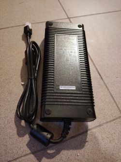
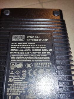
    Quick proof based on the contents of a drawer in the garage
    Voltage regulator for the generator Voltage regulator for the generator
  • #10
    Anonymous
    Level 1  
  • #11
    CosteC
    Level 38  
    spec220 wrote:
    CosteC wrote:
    which gives several dozen amps and next to it put a switching power supply with similar parameters from TME

    CosteC wrote:
    and probably requires more service (e.g. cleaning the fans).

    And the impulse ones that give "several dozen" amperes do not have fans?

    More often they don't have than they have :)
    You give @spec220 some real 250W 12V linear power supply on the hit. Data + photo please. Please show the forum what outstanding constructions I have overlooked in my career. Or please, kindly stop advertising linear power supplies with a transformer as a good solution for power greater than a dozen or so W. Well, unless it's audio-voodoo, but common sense doesn't reach there anyway.

    spec220 wrote:
    CosteC wrote:
    I'm sorry transformer-linear power supply lovers, they're gone, except for a few specific applications.

    Not completely. Here the fact is that the weight and dimensions are large, but believe me, you can build a good linear power supply with quite good efficiency. It is enough to connect transformers with many taps to the binary scale supplying the analog stage, so that it does not have too much voltage margin. Then you will limit the amount of heat loss to a minimum. The fact that such a structure costs a bit, but as someone said "the best doesn't come out of nowhere" :wink:


    Design me a power supply with rope stabilization 5 V 20 A (a mediocre 100 W) so that it works only in the range of 230 V 10% as required by the law and is not destroyed in the range of 230 +/- 15%, also in accordance with the requirements. Efficiency better than 70% under full load - that is grief and sadness in the world of converters. You won't go below 2 kg anyway, despite the fact that such a technical miracle will generate too many harmonics.

    spec220 wrote:
    CosteC wrote:
    I'll throw in: Why two transistors

    You can think hard about this PNP, but I would leave the NPN controlling one. Even in linear power supplies, control transistors are used ... What about a heavily discharged battery, e.g. to 9V? Will you use a divider on the MOS gate that will further reduce the drive voltage?

    When the battery is discharged to 9 V, there is no need to activate the MOSFET - the battery will politely pull the generator to 9 V. When it is 15 V, there will be enough voltage to open the MOSFET, moreover, hardly any mosfet requires more than 7-8 V for rope work.
    The current capacity to charge the gate is enough from the resistor. It doesn't have to be fast. Nothing happens fast there.
  • #12
    Anonymous
    Level 1  
  • #13
    żałosna udręka
    Level 34  
    Let me criticize something. The capacitor loads the zener diode too much. However, I prefer Zener over resistors, because at high values, dust and moisture will affect the voltage of the divider. Why IRF640? Probably because I drew one first. With individual projects, the stock of parameters does not significantly affect the economic calculation, so I allowed myself to be extravagant. Why two Motorola NPN PNP? I assembled on a board without them and there was a weak charge after connecting the battery. Later I realized that it was the fault of the thin wires, and the transistors were already left. I liked the idea of a second optocoupler that turns the circuit on when voltage is applied. Unfortunately, here you can not click helped, so thank you all for your time.
  • #14
    Anonymous
    Level 1  
  • #15
    żałosna udręka
    Level 34  
    spec220 wrote:
    This gives a 100R resistor in series with the zener diode

    That's how it should be.
  • #16
    satanistik
    Level 27  
    Ladies, do you read with comprehension? ;-) I gave the example of the power supply as proof that it is possible to make a system that dissipates a lot of heat and is reliable at the same time, and not that it is better than a pulsed one. As for overvoltages, I can already see how this system responds to a peak with steep slopes fast enough for the transistor to suppress it.
  • #17
    Anonymous
    Level 1  
  • #18
    żałosna udręka
    Level 34  
    The winding does not give more than 2 A, so there will be no heating. The original regulators died when the battery was disconnected. This one will be fine.
  • #19
    Anonymous
    Level 1  
  • #20
    żałosna udręka
    Level 34  
    In practice, it turned out that the capacitor is unnecessary, because it is one winding, so alternating current probably with 300 Hz, so why slow it down? (on the table I played from a linear regulated power supply) In the described system, it currently works without a capacitor and without any problems.