Hello,
Necessity is the mother of invention, sometimes the right equipment is needed for servicing, such as a low-frequency signal generator used to repair amplifiers and receivers. There are a lot of devices on the market, both new and used, but their price is unacceptable to me. So I thought that in order to save costs I would build something like this. The choice fell on a simple sine wave generator with three frequencies: 100 Hz, 1 kHz and 10 kHz, powered from the 230 V mains. I found a description of the electronic circuit on the Internet. It comes from the popular magazine Elektronika Praktyczna 1/95.
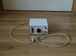
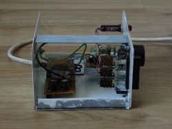
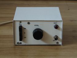
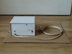
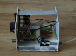
The mechanical construction consists of a base made of steel sheet with two sides riveted to it. The lid is also cut from the same material. The metal pieces were cut with a hacksaw and then bent with a vice in my dad's garage. On it, the power supply is screwed with M3 screws through distance sleeves a few millimeters long. The front panel is made of plastic. On the latter, the so-called a small chassis with a generator board, a dependent isostat switch with frequency selection RC elements, a control lamp and a BNC output socket. The inscriptions were made with a thin waterproof marker. Before final assembly, the steel parts were painted with anti-corrosion paint. The box is permanently connected to the PE conductor of the power cable.
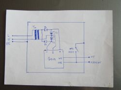
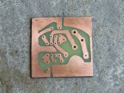
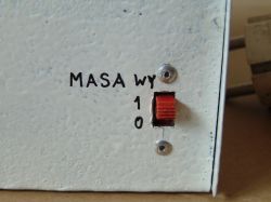
The modules on the boards are connected by thin wires. The power supply includes a TS2/14 domestically produced transformer and a rectifier with a Delon doubler equipped with two filtering capacitors. From it comes the DC voltage of approx. 14 V and the alternating voltage of approx. 11 V to power the control lamp with the telephone bulb. The boards were etched in a solution of sodium persulfate heated indirectly by solar energy, the process for the power supply circuit took about 40 minutes. The Wien bridge generator contains a double TL082 operational amplifier placed in a socket. The first stage produces a sinusoidal signal with the selected frequency, the second is a buffer. A 60V/20mA telephone bulb is used to stabilize the amplitude, and the Telpod CN-15 cermet potentiometer is used to set it. The signal is regulated by a Telpod SP 1.2 carbon potentiometer from zero to approx. 4 Vrms. On the back there is an output ground switch.
The approximate cost is a dozen zlotys and is low due to the use of recycled materials and parts, e.g. a three-core power cord with a plug is made of electronic scrap, the casing sheet was purchased at a local scrap yard, and the plastic is recycled. The rest of the used parts I had from my own stock. The elements that I bought myself are a mains transformer in a stationary store, two electrolytic capacitors (TME) low-SR Panasonic 470 uF/25 V/105 °C and a double operational amplifier TL082 (Allegro). Due to the shortage of some parts, work on this device took about one year.
I add some photos of the project:

Cool? Ranking DIY


