logo elektroda
logo elektroda
X
logo elektroda

DENON RCD-N8 Damaged Power Supply: Standby Repair, ICE3BR1765J, ICE3BR0665J, RC Circuit Changes

Fikszyn 54969 41
ADVERTISEMENT
Treść została przetłumaczona polish » english Zobacz oryginalną wersję tematu
  • #31 18365738
    posili
    Level 10  
    To the given suggestions for repair I will add that after replacing the already mentioned elements, U1 still heats up in the + 12V_D circuit.
    In my case SN7812 its load capacity is 1.0 A.
    Tor + 12V_D supplies 12V circuits but also stabilizers for 7.5V
    + 7V5_D1 circuit has two stabilizers IC282 KIA7808AF and IC283 KIA7808API
    load capacity in total 2.5A, adding to this the circuit load + 12V_D
    it would be advisable to replace U1 with LM7812 (2.0 A)
  • ADVERTISEMENT
  • #32 18510964
    salade01
    Level 2  
    I have the same problem as described in this topic. Suddenly won't power on anymore and standby led no more enlighted. So, I dismounted the unit and took the power supply out. Nicely light brown ... like coming out of a toaster ... in the area around IC871 ... but no component exploded or burnt !
    Nnetheless, I ordered the "repair kit" from England and replaced all delivered components. Unfortunately, it still does not work. When I plug the unit into 230V, it makes some noise (like so many swithching power supply do) and the Power LED enlights red. When I then press the Power button, the LED estinguishes and the noise changes somehow ... but nothing else happens (no display, nothing). The LED only enlights again when I plug the unit out and in again after having waited for a couple of seconds.
    In accordance to another recommendation in this thread, I then unsoldered and measured both 10nF (630V) capacitors (they where not part of the kit ...) but they both seem to be 100% OK (both measured 10,15 nF).
    I feel I will need to make measurements and ask for advice before attempting any other replacement ???

    My questions are:
    - Do you have any other recommendation for me (maybe I have missed something ... somewhere)
    - Is it possible to make the measurements when the power supply is on the bench (completely disconnected from the RCD-N8) and which voltages/points should I ideally check in that situation

    I would be really glad for any advices / recommendations as I love my unit and do not want to trash it !
    Thanks in advance to all
    Gilles
  • ADVERTISEMENT
  • #33 18854364
    rajucorsa
    Level 13  
    Hello. I was struggling with the same problem. RCD-N8, the damaged IC871-ICE3BR1765J system has overheated, it has stratified, I decided to replace it with the original, but it warmed up to 110 degrees, so I changed the R872 resistors as the predecessor proposed for 2x33 Ohm, but the 2W capacitor was also changed from 20uF / C433 25V at 1000uF25V and resistors R873 at 10Ohm (SMD) and R874 at 47Ohm (SMD)
    Currently, after starting in stand-By, the temperature of 22 degrees Celsius but increases and after 2 hours it is 42 degrees Celsius and it does not increase anymore.
    In standby, two chokes squeak in front of the 300uF 400V capacitor and quite irregularly, which is also manifested by temperature jumps on the ICE3BR1765J chip
    do you replace this main capacitor ?? or is this type so Ma ??

    Added after 48 [minutes]:

    Cd ... As for the temperatures, however, they continue to increase, but by 1C / 1h
    currently IC871-ICE3BR1765J has a temperature of 78 ° C, I do not know what temperature is safe for this system, but since it previously had 110 and still works, then there is nothing to worry about. The aluminum heat sink helped for a short time because after a long time, aluminum accumulates heat and without a fan has no effect
    Only for the system itself I gave a 3mm thermopile because the legs could still be soldered. Write down what the temperatures of this system look like in normal operation. Because I do not know whether to combine with a thermocouple from the top of the system and heat dissipation to the housing.
  • #34 19442423
    Tielko
    Level 2  
    Hello from Germany, I have the same problem with my RCD-N8 as all of you. The IC 871 has overheated. I had to replace the R872 and the C875. D874 is broken too.
    But before I convert everything to the better ICE3BR0665J (as described here) and order all parts. I wanted to see that everything works at all.
    I replaced IC871 and everything except for the diode D874.
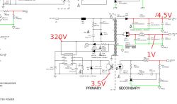
    Now I have in the secondary area -> in the 18V area behind the diode D442 but only 4.5V and between the double diode D441 only 1V and not 5V :( is the IC871 not working properly? I can't get any further here. Better to rebuild everything first or?
    The area IC821 does not work because of the diode -> further to transistor Q822.
    Thanks for a help

    DENON RCD-N8 Damaged Power Supply: Standby Repair, ICE3BR1765J, ICE3BR0665J, RC Circuit Changes
    DENON RCD-N8 Damaged Power Supply: Standby Repair, ICE3BR1765J, ICE3BR0665J, RC Circuit Changes
  • #35 19442601
    398216 Usunięty
    Level 43  
    rajucorsa wrote:
    after a long time, aluminum accumulates heat and has no effect without a fan
    The heat sink was just too small.
  • ADVERTISEMENT
  • #36 19443139
    salade01
    Level 2  
    Did you put some load on the outputs?

    Most switching PS do not work correctly without load!

    Gilles
  • #37 19444533
    Tielko
    Level 2  
    Hello, yes I tested the power supply with the mainboard connected.
    But it can't work without the 5V for the CPU.
    The 18V are for the display. Without the two tensions, nothing should work. Difficult always these switching power supplies :(
    Then I'll have to keep looking.
  • #38 19447762
    salade01
    Level 2  
    Did you change the opto couplers ?

    The fact that your power supply partially works ... but has wrong tensions ... may indicate that the feedback circuit is not working. Opto-couplers and or Zener diodes may be the cause

    Gilles
  • #39 19447933
    Tielko
    Level 2  
    salade01 wrote:
    Did you change the opto couplers ?

    The fact that your power supply partially works ... but has wrong tensions ... may indicate that the feedback circuit is not working. Opto-couplers and or Zener diodes may be the cause

    Gilles


    I unsoldered and measured the optocouplers. They were ok.
    Now I have removed the diode 873 in front of the optocoupler. Did not help.
    Now, as described, I have connected the transistor Q822 -> Emitter to the ground of the power supply via a 120kOhm resistor. On the IC 821 I now have VCC on pin 8 - 0.5 V .
    But unfortunately it didn't help either. Standby does not start and neither does the other.
    Mhhmm just as I write to you and go through everything I have to find out that I think I took the wrong value for the resistor R872 :( shit I installed an 82 ohm for testing and not a 0.82 ohm ..... maybe that's the fault? I don't have one. Then I'll probably order all the parts first and convert everything to the new IC .... 0665J
    Then I hope it works.
    What are the black components, e.g. B 871 (3560) are the coils, right?
    Thanks for your help...
  • ADVERTISEMENT
  • #40 19934968
    Antek-S23
    Level 12  
    Good morning
    I got this power supply to be repaired, unfortunately it was not very professionally dug. On the basis of visual inspection - replaced IC871 with ICE3BR0665 with adjacent areas. Values of the resistors R872 (8.2 ? !!!) and R830 (2.2 ? !!!), R871 - factory value. I replaced these 3 resistors as suggested by the forum, soldered DZ876 18V (its presence does not affect the operation of the system).
    After changes:
    - standby OK (continuous red light)
    - after starting, the light changes to flashing white, typical startup procedure with messages HELLO, CEOC and finally the name of the selected section on the display. After lighting the selected section, the lamp lights up steadily, but after 1-2 seconds it goes out together with the display, the indicator light blinks red approx. 2x per second. When the light is still flashing white, you can select the active section from the list with the button, so the processor is rather efficient. After disconnecting from the mains and discharging the capacitors, the history repeats itself.
    I suspect:
    - some optocoupler (I have already prepared 817C)
    - MOSFET Q821 (I have a STF15N80K5 replacement)
    because it looks like the power section of the power supply does not start.
    I am asking for suggestions, if someone had such a situation, because the PCB may not withstand the next replacement of several or a dozen elements.
    Thanks in advance.
  • #41 19934978
    Gonza
    Level 27  
    Capacitors 10nF / 630V for replacement at the scalak and optocoupler at the zener diode.
  • #42 19935286
    Antek-S23
    Level 12  
    Unfortunately, no changes.
    I do not want to replace all the optocouplers too much.
    Thank you for your attention.

    Added after 19 [minutes]:

    The case was cleared up.
    The power supply was functional, and probably a short circuit on the motherboard forced the overload protection to work.
    When I tried to force a continuation, IC871 exploded.
    Case closed, equipment for electro-scrap.

Topic summary

The discussion revolves around repairing the power supply of the DENON RCD-N8, specifically addressing issues related to the overheating of the IC871 (originally ICE3BR1765J) and modifications made to improve stability. Users share their experiences with replacing the IC with a more robust ICE3BR0665J, adjusting resistors R871 and R872, and removing capacitors C13 and C14 to reduce heat generation. Common failures include damaged diodes (D872, D874) and SMD components, with suggestions to replace optocouplers and check for shorts. The conversation highlights the importance of component selection and layout changes to ensure reliable operation, with several users reporting successful repairs after following the outlined modifications.
Summary generated by the language model.
ADVERTISEMENT