logo elektroda
logo elektroda
X
logo elektroda

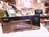
DENON RCD-N8 Damaged Power Supply: Standby Repair, ICE3BR1765J, ICE3BR0665J, RC Circuit Changes

Fikszyn 55095 41
ADVERTISEMENT
Treść została przetłumaczona polish » english Zobacz oryginalną wersję tematu
  • Standby repair:
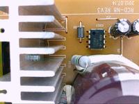
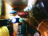
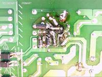
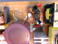
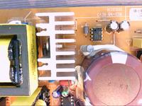
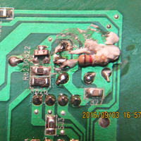
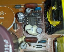
    The original system in RCD-N8 IC871 - ICE3BR1765J (PW & gt; 46W) has overheated and damaged the board. I decided to change the layout on ICE3BR0665J (PW & gt; 74W), of course, it caused small changes in its RC circuit.
    The original: R871-100k? & Gt; br. 2 * 33k? = 66k? 2W / 5%
    C872 for the new 2J 103K
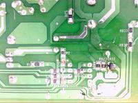
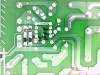
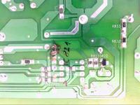
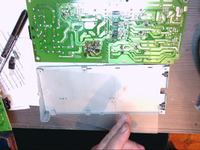
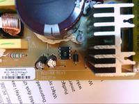
    (!!!) R872-0.82? & Lt; & gt; 0.68 ?. If the current is made on stby and does not heat, the original can be left. If the stby does not go into readiness, check SMD Q822 controlling IC821. In my case, the diodes D872, D874 (for lack of SMD I inserted UF4007) resistor R874 - 10? Have been damaged. The PC871 (817B) optocoupler removed the D873 diode (Zenera protecting it, but it disturbed the optocoupler's operation by lowering the voltage sometimes) and the SJ11 silicon fuse (I inserted the SMD 0 resistor). After the changes, the system works stably, does not overheat. After 1h, the difference in temperature with respect to the environment of 7 ° C! Between the chassis plate and the power supply board I inserted insulation (photo).
    If with this post and photos I helped you click!
    Regards K & amp; K service.
      DENON RCD-N8 Damaged Power Supply: Standby Repair, ICE3BR1765J, ICE3BR0665J, RC Circuit Changes DENON RCD-N8 Damaged Power Supply: Standby Repair, ICE3BR1765J, ICE3BR0665J, RC Circuit Changes DENON RCD-N8 Damaged Power Supply: Standby Repair, ICE3BR1765J, ICE3BR0665J, RC Circuit Changes DENON RCD-N8 Damaged Power Supply: Standby Repair, ICE3BR1765J, ICE3BR0665J, RC Circuit Changes DENON RCD-N8 Damaged Power Supply: Standby Repair, ICE3BR1765J, ICE3BR0665J, RC Circuit Changes DENON RCD-N8 Damaged Power Supply: Standby Repair, ICE3BR1765J, ICE3BR0665J, RC Circuit Changes DENON RCD-N8 Damaged Power Supply: Standby Repair, ICE3BR1765J, ICE3BR0665J, RC Circuit Changes DENON RCD-N8 Damaged Power Supply: Standby Repair, ICE3BR1765J, ICE3BR0665J, RC Circuit Changes DENON RCD-N8 Damaged Power Supply: Standby Repair, ICE3BR1765J, ICE3BR0665J, RC Circuit Changes DENON RCD-N8 Damaged Power Supply: Standby Repair, ICE3BR1765J, ICE3BR0665J, RC Circuit Changes
    It's a foil!

       DENON RCD-N8 Damaged Power Supply: Standby Repair, ICE3BR1765J, ICE3BR0665J, RC Circuit Changes
    And satisfaction, works. :D
    About Author
    Fikszyn
    Level 19  
    Offline 
    Fikszyn wrote 298 posts with rating 78, helped 29 times. Live in city Nad Notecią. Been with us since 2005 year.
  • ADVERTISEMENT
  • #2 14100186
    Fikszyn
    Level 19  
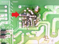
    Replaced by replacing Q-821 STB11NM80 (N-CHANNEL 800 V - 0.35 OHM - 11 A, TO-220), R830 -0.15 ohm (I gave two parallel connected resistors 0.33 ohm / 1W. SMD resistors in the circuit were damaged IC821 can be seen in the photo
    R1-47 ohm and R2-1Kom (evaporated) I also exchanged optocouplers diode D821- UF4007, C821-10nF .No and IC L6565 itself

    Attention!!! on capacitors :!: C821 and C872 103K (10nF / 630V) lose capacity, in my case up to 90% and they were the cause of driver failure and damage IC in up to 7 power supplies, prophylactically replaced in the remaining 3 (the tolerance in them was already within 20%). Probably it will be the main drawback in this equipment :idea: .
  • #3 14237690
    Fikszyn
    Level 19  
    I had several queries about transistor Q-822 (it is being burned), it is smd transistor Marking code BF821 = 1W, BF823 = 1Y, PNP, – VCBO 250,300V. Enables or disables (IC 821) the second power stage of 29V. Check smd resistor R826- 4.7 k Ω which also gets damaged. In case of problems with the key work, connect the Q822 emitter to the mass of the power supply through the 120k resistor # 937; (it is also added in the factory)
  • #5 14359838
    no__name
    Level 15  
    I have a question, I started with some problems converters, now I have quite an unusual phenomenon for me, namely a spark between one of the chokes and Gretza bridge. Everything is perfectly visible in the attached film. It happens irregularly, but only when the capacitor 400v 330uF is discharged. and the first time you plug it in.
    The converter works, but the symptom is disturbing.


  • ADVERTISEMENT
  • #6 14369749
    Fikszyn
    Level 19  
    Frequent fault on these chokes, to replace or rewind. You can replace them with others with similar parameters. Their main task is protection against overvoltage from the network and anti-interference separation on the part of the converter as well as energy accumulation (like the main capacitor on the Gretz bridge). In principle, without it, the power supply will work, but it will interfere with the operation of other devices and will be susceptible to transients from the network.
  • #7 14376168
    no__name
    Level 15  
    Thank you for your response.
    I have also damaged the TH801 thermistor. Is the working temperature ICE3BR0665J in the range 50-60.C is correct, if there are any surprises waiting ...
  • #8 14387020
    Fikszyn
    Level 19  
    In RCD-N8, the original IC871 chip is ICE3BR1765J (PW & gt; 46W) and overheats, which is why ICE3BR0665J (PW & gt; 74W) is used. And you have used this system, if the temperature does not exceed 75 C, it's ok. If you overheat after an hour, check the original layout: R871-100Kom I gave> width. 2 * 33Kom = 66Kom 2W / 5%
    C872 for the new 2J 103K (min. 630V) and R872orginał-0.82 ohm 1.om & lt;> 0.68 ohm (1-2W) according to the manufacturer's specification. The principle is one in the repair of switching power supplies where there is a multitude of unsettled states, we replace all the elements for new semiconductors and capacitors especially, resistors carefully check the overheated replace. And a lot of patience, good luck.
  • #9 14513383
    alain28
    Level 2  
    Sorry to write in english but I am in France.
    I have similar trouble on an unit with STBY PSU failure.
    (this is not unique and to cure it is to change the IC 871)
    But I think that is not good for my unit.

    The PCB is like for you a little burnt.
    Then I have tested on table with 300 ohms on 18v and 11 ohms on 5v
    IC871 is hot, D871 also (less), it is a 470 pf in the snubber circuit hot also.
    I have checked capacitors with RLC bridge, seems ok.
    Change 470 pf by 680 pf (results worst), I don't see on your pictures...

    Thank you.
  • ADVERTISEMENT
  • #10 14520689
    Fikszyn
    Level 19  
    Deleting quite C13, and the temperature drops..But the original layout and IC871-ICE3BR0665J after the change is no longer so much heat.
     C13 was to accelerate the recombination of the carrier in diode D871, but causes some excitation in IC871. I have looked at similar systems, especially the Samsung AH41-01311 power supply present in the HT-C450 / 550 models ... There has never been overheated this circuit and there is no capacitor in the coupling parallel to the diode. I change the IC871 to a stronger equivalent (ICE3BR0665J-PW> 74W) and resistor R871 in series 1W 2 * 33kom (66 kom). But and the original IC871-ICE3BR1765J system after this change stops so much to heat.
    .
  • ADVERTISEMENT
  • #11 14524922
    alain28
    Level 2  
    Fikszyn thank you.
    I will see.
    Here the PSU new is 84 euro ( 2 weeks) with shipment fee.
    I have asked if Denon have made change ( EO or ECO ) but no answer.
    I have loaded the HT-C450 service manual but no schematic on the SMPS.

    Alain
  • #12 14579192
    Fikszyn
    Level 19  
    I attach illustrative SMPS schemes with the ICE3BR0665J system. Please note that there are no capacitors in these diagrams. After removing C13 and C14 capacitors on the Denon SMPS board, the temperature on IC871 and Q821 radically dropped as well as the power consumption without changing the parameters, ie voltage and output current.
  • #13 15910123
    Triseven
    Level 1  
    Q822 not 1Y, but IY on the picture visible.
    IY = KTA 1298 pnp tanzistor 30V, 800mA, 200mW, hfe 100-320. DENON RCD-N8 Damaged Power Supply: Standby Repair, ICE3BR1765J, ICE3BR0665J, RC Circuit Changes
  • #14 15921434
    Fikszyn
    Level 19  
    Triseven wrote:
    Q822 not 1Y, but IY on the picture visible.
    IY = KTA 1298 pnp tanzistor 30V, 800mA, 200mW, hfe 100-320. DENON RCD-N8 Damaged Power Supply: Standby Repair, ICE3BR1765J, ICE3BR0665J, RC Circuit Changes

    possible lack scheme, certainly PNP
  • #15 16673708
    damiandaniel
    Level 1  
    Good day. I told you that I fixed this source with directions, but I have not changed R871, R872, nor removed the D873 diode or C13 and C14 capacitors. It's been over a year and has recently exploded with ICE3BR0665J.
    I thought about repairing it again (looking for damaged items), but about all the changes you indicate. This means that it changes R871, R872 and eliminates D873, C13 and C14.
    But what is the ingredient and what will you put it on?
    Again, thank you very much.

    DENON RCD-N8 Damaged Power Supply: Standby Repair, ICE3BR1765J, ICE3BR0665J, RC Circuit Changes
  • #16 16753110
    sylviob
    Level 1  
    Fikszyn wrote:
    Deleting quite C13, and the temperature drops..But the original layout and IC871-ICE3BR0665J after the change is no longer so much heat.
    C13 was supposed to speed up the media recombination in diode D871, but it caused some excitement in IC871. I have looked at similar systems especially Samsung power supply AH41-01311 on HT-C450 / 550 models ... There is never overheated this circuit and no condenser is coupled in parallel to the diode. Changed IC871 to a stronger equivalent (ICE3BR0665J-PW> 74W) and R871 resistor in series 1W 2 * 33kom (66 kom). But the original IC871-ICE3BR1765J after this change stops so much heat.
    .


    Hi Fikszyn,
    Thanks a lot for your post (and thanks to goodle for the english translation). I have exactly the same problem with RCD-N8, except it hasn't completely burned, so the unit is still working, but shutting down after about 10 minutes.
    I am not very knowledgeable in electronics so I would like to make sure I understand the details of your change:

    I understand the IC871 replacement. But I am not very clear why you replace the original R871 100k with 66k.

    Also you seem to say, removing C13 helps to reduce temperature? Is it enough to just remove this and replace IC871 with original part, but new?

    Finally I'm not very clear about these changes:
    Fikszyn wrote:
    C872 for new 2J 103K (min.630V) and R872orginal-0.82 ohm 1.68mm (1-2W)

    original R872 seems to be 1ohm, you are replacing it with 0.82ohm
    is C872 replacement same as original: 10uF CBB22 630V103J ?

    Thanks
  • #17 16753215
    dobrykamil
    Level 19  
    Hi sylviob.

    I've managed to successfully repair at least 5 units just following OP's guide.Here is what I usually do (assuming IC821 circuit and surrounding components have not been damaged):
    - replace IC871 with the more powerful one ICE3BR0665J
    - remove C13
    - R872 - 0.82 Ohm
    - replace C872 with the brand new capacitor
    - replace R871 with 66k resistor (required with ICE3BR0665J look at the PDFs in post 12)
    After this modification, I can confirm that temperature of IC871 has significantly dropped to about 25-30C.
  • #18 16808976
    porter74
    Level 1  
    Thanks a lot, without your help, I could not fix the power.
  • #19 17049778
    blagosss
    Level 2  
    I warmly welcome.

    I fixed the power supply as described, i.e. ICE3BR0665J, resistors R872 = 0.82 and R871 = 66k and removed the capacitor C13.
    C872 desoldered and measured 12nF, so I left it for now (there was not one in the shop).
    After switching on the mains, the power supply squeaks, and after pressing "power" everything goes quiet and works as it should.
    Can the problem lie in the wrongly selected resistor R872 or maybe the C872, however, replace it?

    greetings
  • #20 17084685
    blagosss
    Level 2  
    After replacing C872 and C821 capacitors with new polypropylene 10nF 5% 1000V, the power supply no longer squeaks. I measured the capacity of the old ones and was 11.8nF and 10.3nF respectively, so it did not diminish but something happened to them.
  • #21 17463050
    Elektroniq
    Level 8  
    dobrykamil wrote:
    Hi sylviob.

    I've managed to successfully repair at least 5 units just following the OP's guide.Here is what I usually do (assumption IC821 circuit and surrounding components have not been damaged):
    - replace IC871 with the more powerful one ICE3BR0665J
    - remove C13
    - R872 - 0.82 Ohm
    - replace C872 with the brand new capacitor
    - replace R871 with 66k resistor (required with ICE3BR0665J look at the PDFs in post 12)
    After this modification, I can confirm that temperature of IC871 has significantly dropped to about 25-30C.


    Hello, I decided to repair my denon according to your instructions. I ordered the ICE3BR0665J chip and received the ICE3BR0665JZ with the 3BR0665JZ designation with 7 and not 8 pins. In the note from what I was able to read is the same layout only in a different housing but I was concerned about the power parameters - 71 and 49W instead of 74 and 49W in ICE3BR0665J. Now I have a dilemma whether this system is actually the same. Will the resistors in this case 66K not change? Thank you in advance for your help. greetings
  • #22 17484556
    Fikszyn
    Level 19  
    Elektroniq - You can try the same parameters, some newer version (Drain 650V1-ok). I am sorry for answering so late but I do not have time on the forum. Remember that on the primary side what converter inverters exchange all semiconductors, this applies in particular to diodes that can look good on the measuring device, and in fact under the influence of voltage, frequency ... etc. change their parameters. I appreciate and good luck.
  • #23 17490378
    Kubabidn
    Level 2  
    I also have a problem - during removal by one of the forum participants. I will let you know if I have succeeded. :-)
  • #24 17510494
    Kubabidn
    Level 2  
    Kubabidn wrote:
    Hello, would anyone take a paid repair of this power supply? Local services in my town have unfortunately been slowed down ...

    Welcome back. The power supply is being repaired by one of the forum participants. I'll let you know how it went :-)
  • #25 17719442
    xxl245
    Level 16  
    Hello all.

    Help me, gentlemen, because I lack strength and the nearest electronic store is 50 km
    No standby
    Replaced:
    C872 103k 630v
    C821 103k 630v
    R872 I gave 2x0.33 2W was damaged
    Ic871 ICE3BR1765J was damaged
    D874 I gave uf4007
    D872 I gave uf4007
    one was damaged but I exchanged both
    Sj11 I gave resistor 0 was damaged

    I guess that the required standby is 5v on a large socket, I jump from 2.3 to 2.4v (checked on the table without connecting to the rest)
    I have not mentioned the pc871 optocoupler yet, can it cause such problems?
  • #26 17719630
    kjurek

    Level 16  
    Replace all 4 optocouplers 817. This is the basis.
    Carefully check that you do not have a break with the mentioned system, magnifier or ohmmeter and check if there is a transition leg - element.
  • #27 17721833
    xxl245
    Level 16  
    kjurek wrote:
    Replace all 4 photocells 817. That's the basis.
    Carefully check if you have a break with the system, magnifier or ohmmeter and check if there is a leg of the system - element.


    Thanks for the answer.

    Optocouplers checked and all functional, but I replaced them prophylactically, unfortunately without any changes
    February on the chip checked and everything seems to be ok.

    In addition, I noticed that line 18v has a short to ground.

    I've created a new topic, no one seems to follow this one anymore

    However, the problem was solved thanks to the founder of the topic.
    In my case, voltage spikes caused diode D873
  • #28 17776608
    Kocourek
    Level 1  
    Hello, help with the repair denon, I write through a translator, maybe it will be inaccurate. I am a pensioner from Prague, a former television restorer, and I manage my son DENON-RCD-N8 after IO ICE3BR1765J, and the rest of the part has started to work partially. I have 5 V + 18 V ok. I do not have 12 V. It has a defective resistance R826 = 4.7 Kom replaced. I do not have VCC on L6565. Now "Hellou" and "COOL" appears after switching on, then after disconnecting power from the socket and repeating this waiting time.
  • #29 18058277
    Aung Kyaw Soe
    Level 1  
    Sorry for English!
    Thank you “alain28 #11
    I also having same problem and want PSU (new) board and replace. Is it OK now? Where did you buy, link please!

    “Fikszyn thank you.
    I will see.
    Here the PSU new is 84 euro ( 2 weeks) with shipment fee.
    I have asked if Denon have made change ( EO or ECO ) but no answer.
    I have loaded the HT-C450 service manual but no schematic on the SMPS.
    Alain”
  • #30 18332904
    MBB001
    Level 1  
    My board clearly shows a burn mark on the power pcb. I found this online: Denon RCDN8 12 piece power supply service repair kit (standby circuit) for 18,80 British pounds. I hope this is easy enough for me to fix my Denon, I am not very tech savvy so I can't comment on how this is different from the suggestions in this thread.

    Parts list
    1 x IC871, ICE3BR1765J I.C
    1 x D871, 1N4007 Diode
    1 x D872, SMD Diode
    1 x D874, SMD Diode
    1 x C874, 47uf Capacitor
    1 x C875, 0.47uF Capacitor
    1 x R872, Resistor ● Upgraded
    1 x R873, Resistor ● Upgraded
    1 x R874, Resistor ● Upgraded
    1 x D873, Zener Diode
    1 x SJ11, SMD 0R0 Link
    1 x PC871, SMD Optocoupler

    I can't post a direct link, so here is where you can find it (not affiliated): sparedparts.com/collections/rcd-n8-1/products/3402196

    DENON RCD-N8 Damaged Power Supply: Standby Repair, ICE3BR1765J, ICE3BR0665J, RC Circuit Changes

Topic summary

The discussion revolves around repairing the power supply of the DENON RCD-N8, specifically addressing issues related to the overheating of the IC871 (originally ICE3BR1765J) and modifications made to improve stability. Users share their experiences with replacing the IC with a more robust ICE3BR0665J, adjusting resistors R871 and R872, and removing capacitors C13 and C14 to reduce heat generation. Common failures include damaged diodes (D872, D874) and SMD components, with suggestions to replace optocouplers and check for shorts. The conversation highlights the importance of component selection and layout changes to ensure reliable operation, with several users reporting successful repairs after following the outlined modifications.
Summary generated by the language model.
ADVERTISEMENT