logo elektroda
logo elektroda
X
logo elektroda

Voltage in the MPPT string and the efficiency of the inverter

radekone 19692 16
ADVERTISEMENT
Treść została przetłumaczona polish » english Zobacz oryginalną wersję tematu
  • #1 14105267
    radekone
    Level 13  
    Imagine a 4kw system based on two strings of eight 250W panels each.

    There are two types of panels to choose from, one with Vmp = 30v, Voc = 37V. The second type is Vmp = 49V, Voc = 60V.
    The efficiency of the panels is omitted or assumed to be the same.
    We assume that the currents are within the operating range of the inverter.
    We assume that the operating range of the inverter is 200-500V (*) at nominal power, its maximum voltage is 550V, and the starting voltage is 150V.

    The first set of panels will therefore operate in the range of 208-328V (taking into account the temperature coefficients 8 * 26V - 8 * 41V).
    The second set will operate in the range of 334-528V (8 * 42V - 8 * 66V), which is at the limit of the inverter's voltage withstand (*).

    We read from the chart that in the entire power range the inverter achieves the highest efficiency at 370V (97.5%). At 200V its efficiency decreases by 1.5%, at 530V by 0.5%

    Conclusion number one: assuming that the entire system will most often operate at a voltage around Vmp, a set of panels with a higher nominal voltage should give better efficiency (97.5% vs 96%, i.e. about 50 kWh per year).

    Conclusion number two: higher voltage-> lower current-> lower cable losses

    Conclusion number three: System number two will turn on the inverter faster in the morning when the light is still low, because:
    Vst / panel 150V / 8 = 19V.
    19V = half the Vmp of panels 1
    19V = one-third of the Vmp of the panels 2

    (*) We also have an alternative inverter 150-580V, max 600V

    Do I understand correctly or do I still have to read?
  • ADVERTISEMENT
  • #2 14105302
    prose
    Level 35  
    With this faster inverter switching on, do not overdo it, I have 2 strings of 250 V and 380 V and somehow they start evenly.

    Added after 2 [minutes]:

    And when you get a faster start in the morning, you will get max 10 Wh.
  • #3 14105724
    grzegorz dob.
    Level 20  
    I would use set no. 2 (higher voltage) will work better in low sunlight. You will not reach max voltage under load. Only when you can reach the max is if the inverter is unloaded. Correct reasoning.
  • #4 14109708
    radekone
    Level 13  
    prose wrote:
    With this faster inverter switching on, do not overdo it, I have 2 strings of 250 V and 380 V and somehow they start evenly.
    Added after 2 [minutes]:
    And when you get a faster start in the morning, you will get max 10 Wh.


    Thanks for the information. So there is nothing to crush the copies about. There it was just about the difference between 120V and 150V.

    Quote:
    I would use set no. 2 (higher voltage) will work better in low sunlight. You will not reach max voltage under load. Only when you can reach the max is if the inverter is unloaded. Correct reasoning.


    Exactly, with this insolation it is different for me.
    And how to connect, for example, 14 'low voltage' panels into one string, will it balance itself then? Then it would be the range 364-574V. As I understand it, at air temperatures of 5-18C, which I have for most of the year, the voltage would oscillate around 14 * 30V = 420V, which is almost perfect?
    (In the case of 15 panels it would be 390-615V; although you will not achieve this highest, you shouldn't design the network that way?).
  • ADVERTISEMENT
  • #5 14109931
    prose
    Level 35  
    I chose springi to the MPPT voltage range for me at fronius and g 60 hv is 280 V, the highest yield from PV.
  • #6 14126338
    grzegorz dob.
    Level 20  
    Do not exceed the voltage of the panels in the open circuit in relation to the maximum voltage of the inverter, because it may happen that with very good sunlight they will turn off the AC mains voltage and the inverter will turn off the voltage of the panels at the inverter input. What causes damage to the inverter input (in a good system by over-voltage protection). Summing up, the voltage of the panels in the open circuit must not exceed the max voltage of the inverter.
  • ADVERTISEMENT
  • #7 14126953
    Lesio_Q
    Level 20  
    I am afraid that in that case the overvoltage protection on the input of the inverter is a fiction.
    There is sometimes a varistor that will fry until it burns, because I have doubts whether it will be able to absorb excess energy for a long time.
    And besides - you can only hope that one of the paths will get burned without causing a fire.
    Is there any other scenario for sunny day and inverter input voltage overrun? Is there a 'crowbar' system that permanently shortens the string when the voltage is exceeded?
    Piotr.K
  • #8 14129060
    grzegorz dob.
    Level 20  
    They gave Danfoss a 7A fuse and this is the maximum input current, then the overvoltage scenario should be: (closes the varistor and burns the fuse). but is it so? It can be different for each inverter.
  • #9 14129094
    Lesio_Q
    Level 20  
    In such a scenario, there is a problem, because every owner dreams that the PV panels work at a current close to the short-circuit current, so the fuse should not only be special
    - DC to high voltage, because the arc will burn for a long time, it could limit their power output during operation.
    I can see it more so that the varistor has a voltage much higher than Umax MPPT, and the disconnection of the current consumption from the PV is done by switching off (PWM = 0) the input DC-DC converter working as MPPT.
    In short - active protection, based on the measurement, without burning any pre-planned element in the inverter.
  • #10 14129168
    grzegorz dob.
    Level 20  
    In my Danfosse, the MPPT voltage is 200V-500V and the max voltage is 600V, so after exceeding 600V something will fall. each element has its own maximum voltage.
    In summary, do not exceed the Max voltage.
  • #11 19799718
    Marek4440
    Level 1  
    Hello,

    I have a practical question - I intend to purchase a 4.86 kW installation with a FoxESS T5 inverter (with expansion in mind in a few years). I am supposed to wear Jinko Tiger N Tr66, 405W panels, which have a Vmp 36.33 V, Temperature Coefficients of Voc is -0.28% / C. I want to put on 2 strings of 6 panels on the south side, rather unshaded. And question: the inverter has a starting voltage of 180V in the specification, MPPT voltage range 160-850, but also "MPPT voltage range (at full load) 210-850".

    Questions:
    1. The starting voltage of 180 V refers to the total voltage of both strings (summed up), or to each of them separately (therefore, whether a given string is to be taken into account by the inverter, whether it must reach 180 V, or is it necessary to obtain the sum (I suspect that, of course, taking into account the MPPT voltage range) was at least 180 V?
    2. Should the minimum voltage value of 160 V or 210 V be taken into account for each MPPT for 2 strings?
    3. Because - unless I was wrong - Vmpp at a temperature of 70 degrees Celsius will be 31.75 V for panels, and therefore with 6 panels - 190.5 V, does it make sense to mount such a string with this inverter at 180V voltage initial (the question of when the inverter starts up, or if the string is cut off during operation due to voltage drop (e.g. a bird gets dirty on the panel)),
    4. What would be the difference in efficiency (and in the produced kW) if you had 2 strings of 6 panels compared to the situation if you were to make 1 string out of 12 panels?
    5. While my above calculation of Vmpp at 70 deg. Is correct, if the inverter receives from 1 string or from the summed strings at tem. 70 degrees C 381 V (in the case of STC 436 V (2x 218 if there were 2 strings), and in NMOT 404.4 (2x 202.2 if there were 2 strings), and the nominal efficiency is 600V, what will be the efficiency inverter at such voltages? Will it be influenced by the division of the installation into 2 strings? Would it (and if) be important to add, for example, 2 panels (i.e. approx. 60-70 V)?
    6. How important for the answer will the passage of time be (hardware degradation - with the panels there is information about the guarantee of 87% yield over 30 years - can you believe it?)?
    7. Is it possible to control the voltage in the installation with the T5 inverter, so as to notice that something bad is happening to any of the panels if I decided to use 1 string (this control was to be divided into 2 strings with 6 panels each - production from in the same position, it should be comparable with the proper operation of the installation)
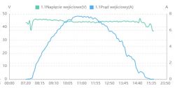
    8. Does the panel produce current with the same voltage, but only with a different intensity, since it was started in the morning (let's assume a constant temperature)? In other words - will 6 panels at once (when the first rays of the sun fall on it) at e.g. a temperature of 70 degrees C (which of course is impossible in practice, but it probably does not matter for the question) will work at 31.75 V, or it will also reach this value, e.g. for an hour or more and during the day, depending on the insolation (at the same temperature), will the voltage fluctuate?


    Thank you very much in advance for your answer. The matter is quite urgent due to the choice of the installation supplier.

    Regards
  • #12 19799813
    kosmos99
    Level 38  
    1. To each one separately. There must be at least 180V on each string.
    2. 160V is the start of work, to be able to obtain the maximum power, the voltage must be at least 210V.
    3. In my opinion, at least 1 panel must be added
    4. It depends on the conditions, especially shade and dirt. The problem with one panel in the case of one string affects the entire installation, when there will be only two strings in a half. With two of the same strings, we also have better diagnostics. If the conditions are the same, better performance and lower installation price will be for one string.
    5. You need to look at the characteristics of the inverter.
    6. In Poland, nobody has had a PV installation for that long, so it is difficult to find an answer. The more that now there is probably a different production technology
    7. There will be only one value for current and voltage. The inverter cannot control individual panels. Alternatively, setting up optimizers makes it possible. However, if there is no shadow, there is no economic sense to install them just for this.
    8. The voltage at constant temperature changes little. You have to take into account that the temperature increases during operation, so the voltage decreases.

    Added after 2 [minutes]:

    Marek4440 wrote:
    I intend to purchase a 4.86 kW installation with the FoxESS T5 inverter (with expansion in mind in a few years). I am supposed to wear Jinko Tiger N Tr66, 405W panels, which have a Vmp 36.33 V, Temperature Coefficients of Voc is -0.28% / C. I want to put on 2 thongs of 6 panels on the south side, rather unshaded.


    But there is no point in expanding it anymore. (5kW inverter and 4.86 panels)
  • #13 19799912
    jsw
    Level 14  
    Ad 8. graph of the panel output (here exactly as optimizer inputs)
    Voltage in the MPPT string and the efficiency of the inverter
  • #14 21155845
    gorajczanin
    Level 6  
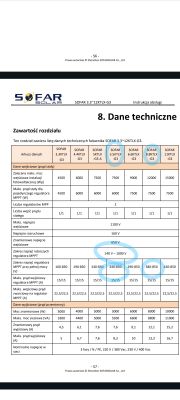
    I have 2 strings. One 6x33V=ok 200V and the other 6x39V =ok 240V. Currently on a sofar 3.6 ktlm g3 inverter it is running well because the voltage range of the regulator
    MPPT at full power is from 160 to 1000V.
    I want to change to a 3 phase 5.5 ktlx g3 but there
    MPPT regulator voltage range at full power
    (V) is 240-850. my question: will the first weaker string which is always around 200V work at full power? I will add that the operating voltage range of the inverter is 160-1000V. The 8.8 inverter has the same operating voltage range but at full power 380-850V here both strings are much lacking. How do I understand all this? Is there any point in fitting the 8.8? In the future I will certainly add panels, but I want to start by replacing the inverter. Technical data table for SOFAR 3.3~12KTLX-G3 inverters. @ElektrodaBot
  • ADVERTISEMENT
  • #15 21156248
    Strumien swiadomosci swia
    Level 43  
    radekone wrote:
    The other type is Vmp=49V, Voc=60V.
    .
    What type of panels are these?
  • #16 21156260
    gorajczanin
    Level 6  
    On the roof (Azimuth 135°) 6x Jinko Tiger Pro monofacial 545W, and on the structure (Azimuth 185°) 6x Longi 370W mono.
    I still have space on the roof, but if I add panels, it will be even later to start production, because the neighbour's Christmas tree casts a shadow.
    The structure is only for 6 panels, so expansion without another structure not possible.
    I think I'll do the conversion to 3 phases for the time being, I'll report the existing extension (because the construction hasn't been reported yet, because it's too much for 1 phase 🤣), and sometime there I'll buy a 3.3 or 4.4 KTLX G3 inverter and have 2 inverters running on the current panels.
    But as I asked at ZE about the 2 inverters, it is possible, but you have to connect them via RS485 or via SunSpec. It's just that I don't have anything on my current inverter with such ports 🥵
    As you can see a river topic 🤪

Topic summary

The discussion revolves around the efficiency of inverters in relation to the voltage output of solar panel strings. Users compare two types of panels: one with Vmp = 30V and Voc = 37V, and another with Vmp = 49V and Voc = 60V, considering their performance under varying sunlight conditions. The inverter's operating voltage range is noted as 200-500V, with a maximum of 550V and a starting voltage of 150V. Participants emphasize the importance of not exceeding the inverter's maximum voltage to prevent damage, discussing potential overvoltage protection mechanisms. The conversation also touches on practical installation scenarios, including the configuration of multiple strings and the implications of panel voltage on inverter efficiency. Users share experiences with different inverters and panel configurations, highlighting the need for careful planning to optimize performance.
Summary generated by the language model.
ADVERTISEMENT