logo elektroda
logo elektroda
X
logo elektroda

Mains-Generator Switch Diagram: Modernizing Electrical Installation, Relay Station, N Wire

bobeke 46386 24
ADVERTISEMENT
Treść została przetłumaczona polish » english Zobacz oryginalną wersję tematu
  • #1 14128319
    bobeke
    Level 15  
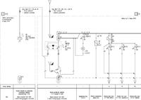
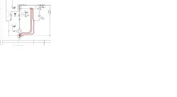
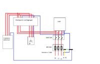
    Hello, I want to modernize the electrical installation of the relay station (installation of the network/aggregate switch). The problem is that the power cable of the station has a permanently connected N wire to the terminal strip in the cable connector (behind the power fuses - reworking is not an option). In normal cases I had no problem, because the power went to the meter, then to the switch and from the switch (together with N) to the receiver. I have doubts about this cable.

    Will the assembly diagram that I quickly drew in a well-known graphics program be suitable?

    N stands for neutral wire

    Please help, suggest Mains-Generator Switch Diagram: Modernizing Electrical Installation, Relay Station, N Wire
  • ADVERTISEMENT
  • #2 14128658
    Gregory_bg
    Level 26  
    I don't luv this drawing at all :/ a diagram would be better, not such a painting. The mains/generator switch must isolate power from the mains and from the generator. The question is whether it is a manual switch or an automatic one
  • #3 14128891
    bobeke
    Level 15  
    I'll try to draw something in the right program tomorrow if I have more time. Manual switch for information.
    Like on this page:

    link

    Generally there is a problem with the neutral wire. In this situation, it is not separated by a switch.
  • #4 14129079
    Gregory_bg
    Level 26  
    You should have no problems with connecting the wires to the switch if you have the knowledge and you need to do something with the neutral wire, I'm skipping the issues of the aggregate and what about fire protection. of this device
  • ADVERTISEMENT
  • #5 14129171
    bobeke
    Level 15  
    All this fuss about neutral. So far, it looks like that when the power supply from the mains is switched on, the voltage is supplied to the station (3 phases and neutral). When switching on the power from the generator, the voltage from the connection socket (3 phases) went through the switch to the station - N of the receiver, permanently connected to the ZK. It works so far despite not separating this wire (I don't know how). I don't understand how it was supposed to work since the zero voltage from the generator was not connected at all. The only thing that comes to my mind is that some magician could have put a zero on the protective pin, which de facto connects directly to the neutral wire.
    The distance of the RP from the station is good 3 km (some ground, some overhead). As for protection, there is a whole lot of RCD, overcurrent, overvoltage, etc. switches inside. I generally described the receiver as a whole station.
  • #6 14129294
    Gregory_bg
    Level 26  
    I do not know how it works and why it works, etc. At work, where I encounter power from aggregates, either from a hand or from an automatic machine, the outermost wires are separated from each other so that one power source does not affect the other
  • ADVERTISEMENT
  • #7 14129386
    JohnySpZOO
    Electric installations specialist
    Connection diagram of the genset-0-grid power switch for the TN-CS system in a single-family house that I used to do:
    Mains-Generator Switch Diagram: Modernizing Electrical Installation, Relay Station, N Wire
  • #8 14136469
    bobeke
    Level 15  
    Hello, problem solved. The diagram I drew is correct. The neutral is not separated by the genset mains switch. This solution is accepted by the power industry due to the fact that a separate line with a transformer is connected to the ZK and is located right next to the medium voltage station. The previous assembly was incorrectly performed.
    Weird way of mounting the switch. I encountered this for the first time.
  • #9 17779767
    MartinezVip
    Level 10  
    JohnySpZOO wrote:
    Connection diagram of the genset-0-grid power switch for the TN-CS system in a single-family house that I used to do:
    Mains-Generator Switch Diagram: Modernizing Electrical Installation, Relay Station, N Wire


    I warmly welcome,
    please let me know what is the purpose of this additional connection from the PEN section bypassing the switch, I see that the switch is 3P+N which means N inseparable, is it an additional protection against a possible failure of the switch and cutting off the N track? but how can a permanently short-circuited N track in a switch fail?
    Mains-Generator Switch Diagram: Modernizing Electrical Installation, Relay Station, N Wire
  • #10 17779858
    JohnySpZOO
    Electric installations specialist
    MartinezVip wrote:
    I warmly welcome,
    ... I see that the switch is there 3P+N which means N inseparable ,
    Are you sure?
  • #11 17779885
    MartinezVip
    Level 10  
    JohnySpZOO wrote:
    MartinezVip wrote:
    I warmly welcome,
    ... I see that the switch is there 3P+N which means N inseparable ,
    Are you sure?


    Thanks, in fact, this HIM406 is 4P and not 3P+N, I was confused by the description in the diagram, now if I understand correctly, this connection makes sense because the author of the installation project used a 4P RCD for 1P circuits?

    The second case - for TN-CS installations where the division into PEN into PE and N is in the ZE connector and then WLZ 5x10mm flies into the building, i.e. it flies as TN-S, I understand that for installations where RCD 4P are applicable only to 400V and RCD circuits 2P are applicable only to 230V circuits, I understand that I can try to disconnect the N track?
    I will add that the ZE told me that in my case (PEN division in their connector) it doesn't matter to them, because it is already on my side of the installation.
  • ADVERTISEMENT
  • #12 17780217
    mawerix123
    Level 39  
    MartinezVip wrote:
    3P+N which means N inseparable,


    This is not true, the installation switch or the 3P+N power switch is designed to disconnect the N line, in this case N is connected first before the phase contacts and disconnected last, only such a disconnector should be used to disconnect N in a 3-phase system.
  • #13 17780305
    MartinezVip
    Level 10  
    mawerix123 wrote:
    MartinezVip wrote:
    3P+N which means N inseparable,


    This is not true, the installation switch or the 3P+N power switch is designed to disconnect the N line, in this case N is connected first before the phase contacts and disconnected last, only such a disconnector should be used to disconnect N in a 3-phase system.


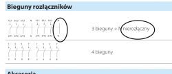
    honestly, I haven't met one like that, I'll honestly watch it, usually producers, as they say 3p+N, is inseparable, even the famous SAMPEL:
    https://www.elektrykasklep.pl/towar/przk-3063n-w01-spamel-przelacznik-zrodla-zasilania/
    If you can show it to me, I'd love to see it :)
    Coming back to the topic, I'm more interested in the answers to my questions in post #11
  • #14 17780343
    mawerix123
    Level 39  
    MartinezVip wrote:
    If you can show it to me, I'd love to see it


    e.g. hager SF463

    MartinezVip wrote:
    usually manufacturers say 3p+N then N is inseparable


    OK, N is unbreakable and there is information about it
  • #15 17780364
    MartinezVip
    Level 10  
    mawerix123 wrote:
    MartinezVip wrote:
    If you can show it to me, I'd love to see it


    e.g. hager SF463

    MartinezVip wrote:
    usually manufacturers say 3p+N then N is inseparable


    OK, N is unbreakable and there is information about it


    with you Hager, the manufacturer does not provide anything except that it is 4P, i.e. N disconnected, I will not mention that the manufacturer does not mention anything about this order of switching on / off N, so we predict?
  • #16 17780423
    mawerix123
    Level 39  
    MartinezVip wrote:
    with you Hager, the manufacturer does not provide anything except that it is 4P


    After all, we have a description: Modular power switch 3P+N I-0-II 63A 400VAC

    MartinezVip wrote:
    I will not mention that the manufacturer does not mention anything about this order of connecting / disconnecting N, so we are telling?


    There was already such a topic, my friend's dilemmas were discussed in it, friend emigrant he bought it himself and proved that the SF463 works as I wrote, the representative of Hager could not answer whether this camera works like that.
    I got bored of rolling .. 4P vs 3P+N disconnectors there is a full one on the electrode, let everyone rock with this problem himself ;)

    EDIT:
    especially for a friend I found this thread: https://www.elektroda.pl/rtvforum/topic3349285-90.html#16714325#16714325

    enjoy reading from reading "divination" ;)
  • #17 17780481
    JohnySpZOO
    Electric installations specialist
    MartinezVip wrote:
    usually manufacturers, as they say 3p+N, N is inseparable, even the famous SAMPEL:
    https://www.elektrykasklep.pl/towar/przk-3063n-w01-spamel-przelacznik-zrodla-zasilania/

    And is it possible that a person typing on a keyboard can make a mistake and the crowd can repeat it unconsciously?

    Designation: 3P+N - principle of operation: link
    So how is it with this 3P+N at all?
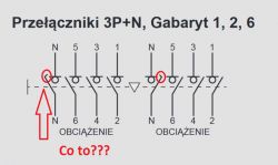
    Mains-Generator Switch Diagram: Modernizing Electrical Installation, Relay Station, N Wire

    Do you have this in Spamel's switch diagram?

    In the will of accuracy - on the diagram I GUESS there is an error with a given HIM406 switch model. At the stage of creating the schematic, calling Hager's technical support, the advisor presented this solution as 3P+N - that it was supposedly a mistake in the marking and that's how it went. 3P+N or 4P - theoretically, the difference is not visible when looking at the housing.
    I will not physically buy this apparatus and I will not check out of curiosity whether the track connects/disconnects first/last or evenly with the phase ones.

    emigrant wrote:
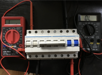
    I will return to the subject of the aggregate a little, but not completely. Hager SF463 power switch arrived today. In another topic (https://www.elektroda.pl/rtvforum/topic3350913-60.html) the topic of this switch was discussed, specifically whether the N pole has a time delay or not. Since there were any objections to this, I simply wrote to the Hager company, whether it is a 3P+N switch, where the N pole has a time delay, or a 4P one. I contacted twice and each time got the answer that it is a 4P switch, all poles turn on and off simultaneously. Even people from Hager Polska contacted some engineers, etc. Blah blah...

    I checked in a rather simple and even crude way whether the N pole has a delay. It took 2 multimeters and you can see when the contacts are connected. In addition, by switching up or down we have such a double-click. There are like 2 stages of switching and you can feel it at hand. The N pole is activated first, followed by the phase poles. This gap is quite large, suggesting only "wajcha". Some ~10 mm still need to cover the arc paths to connect the phase contacts.

    It's strange that the manufacturer himself misleads the customer. They do not have exact knowledge of their product. Even the blue marking of the N pole suggests that it is or could be 3P+N and not 4P.
    Mains-Generator Switch Diagram: Modernizing Electrical Installation, Relay Station, N Wire


    Now the question is, was this adviser telling the truth or lying? Was he a good and underrated technician or was he from a round-up? Does he still work at Hager?
    I will not answer.

    PS Not everything that is written in the catalog cards is true. There are often mistakes because the order went to print and the cost of not completing it is much higher than the value of the order. Also, is there a bug in this case ... I still don't know.
    Do not look at what manufacturers write, but at general technical knowledge and accepted principles. When you find a babola, pick up the phone and call the manufacturer with a question.

    I do not know spamel's offer for power switches because I do not sit on these topics anymore, but at the time 3P + N was with this red circle, which, according to. theory had its justification when switching on and off the N track.
  • #18 17780715
    MartinezVip
    Level 10  
    mawerix123 wrote:
    MartinezVip wrote:
    with you Hager, the manufacturer does not provide anything except that it is 4P


    After all, we have a description: Modular power switch 3P+N I-0-II 63A 400VAC

    MartinezVip wrote:
    I will not mention that the manufacturer does not mention anything about this order of connecting / disconnecting N, so we are telling?


    There was already such a topic, my friend's dilemmas were discussed in it, friend emigrant he bought it himself and proved that the SF463 works as I wrote, the representative of Hager could not answer whether this camera works like that.
    I got bored of rolling .. 4P vs 3P+N disconnectors there is a full one on the electrode, let everyone rock with this problem himself ;)

    EDIT:
    especially for a friend I found this thread: https://www.elektroda.pl/rtvforum/topic3349285-90.html#16714325#16714325

    enjoy reading from reading "divination" ;)


    Thanks :)

    Added after 3 [minutes]:

    JohnySpZOO wrote:
    Do you have this in Spamel's switch diagram?


    This Sample is N has inseparable

    Mains-Generator Switch Diagram: Modernizing Electrical Installation, Relay Station, N Wire

    Added after 10 [minutes]:

    Colleagues, thank you very much for the material, but I'm more interested in:

    for TN-CS installations where the division into PEN into PE and N is in the ZE connector and then WLZ 5x10mm flies into the building, i.e. it flies as TN-S, I understand that for installations where RCD 4P are applicable only to 400V circuits and RCD 2P are applicable only to 230V circuits, I understand that I can try to disconnect the N track with the power switch? phase-to-phase surges can occur? and I do not mean damage to N in the operator's network or in WLZ
    I will add that the ZE told me that in my case (PEN division in their connector) it doesn't matter to them, because it is already on my side of the installation.

    Probably with this switch where this selectivity of switching on/off N in the TN-S system is used, I assume that I can disconnect it, but I was thinking about this switch:
    http://www.hager.pl/katalog-produktow/energy-...lar-power-switches-with-rotary-drive-20-80-a/ him406/32354.htm

    only this one is an ordinary 4P switch for all paths and here I understand it is better not to disconnect the N path.

    Generally, I am interested in the topic of possible phase-to-phase overvoltages when switching with this Hager HIM406 switch in a switchgear where 4P RCDs apply only to 400V circuits and where 2P RCDs apply only to 230V circuits, can phase-to-phase overvoltages occur (when switching power supply with this HIM406) only in the case of use of RCD 4P for circuits 1P ?
  • #19 17780866
    mawerix123
    Level 39  
    MartinezVip wrote:
    then I understand that I can try to disconnect the N track with the power switch?


    It seems to me that you should, but it should be included in the letter from your energy supplier that has guidelines for connecting the generator.

    MartinezVip wrote:
    Generally, I am interested in the topic of possible phase-to-phase overvoltages when switching with this Hager HIM406 switch in a switchgear where 4P RCDs apply only to 400V circuits and where 2P RCDs apply only to 230V circuits, can phase-to-phase overvoltages occur (when switching power supply with this HIM406) only in the case of use of 4P RCD for 1P circuits?


    I will write you this, if you use HIM406, there may be a situation that between N and the phase wire in the switchgear there will be a voltage higher than 230V and RCD 4P or 2P will not help here
  • #20 17780927
    MartinezVip
    Level 10  
    mawerix123 wrote:
    I will write you this, if you use HIM406, there may be a situation that between N and the phase wire in the switchgear there will be a voltage higher than 230V and RCD 4P or 2P will not help here


    unless with the HIM406 I will leave the N track inseparable and only the phases will be switched, I understand it correctly?
  • #21 17781117
    emigrant
    Level 29  
    What are you so excited about with HIM406? You already bought it and are looking for applause that HIM406 is the right purchase? Either you mount a 3P+N switch with disconnectable N or non-disconnectable. No 4P is involved.
  • #22 17781155
    MartinezVip
    Level 10  
    emigrant wrote:
    What are you so excited about with HIM406? You already bought it and are looking for applause that HIM406 is the right purchase? Either you mount a 3P+N switch with disconnectable N or non-disconnectable. No 4P is involved.


    please explain to me what will be the difference if I use a switch with a non-separable N track compared to the use of a 3P switch, leaving the N track shorted in the distribution block?
    I see no difference.
  • #23 17781346
    mawerix123
    Level 39  
    MartinezVip wrote:
    please explain to me what will be the difference if I use a switch with a non-separable N track compared to the use of a 3P switch, leaving the N track shorted in the distribution block?
    I see no difference.


    And I can see the difference, but this difference results from how, when and where this switch is mounted, whether it is a network-grid system or a generator network, etc. ... I wrote above about the energy supplier but not a word from you how yours approaches it supplier, I suspect you haven't even contacted ZE about this. It often happens that the supplier provides a condition for connecting the generator if all working cables will be disconnected from the network and N is such a cable.
    Whether you see the difference or not, it doesn't matter and I will ask you a question .... I will show you a wire with an insulated end and ask if you can see the difference if there is or is no voltage in it :?: I can't see it will continue to look as innocent and yet be deadly.

    How does your generator work? :?: TT or TN-S :?:
  • #24 17781549
    MartinezVip
    Level 10  
    mawerix123 wrote:
    MartinezVip wrote:
    please explain to me what will be the difference if I use a switch with a non-separable N track compared to the use of a 3P switch, leaving the N track shorted in the distribution block?
    I see no difference.


    And I can see the difference, but this difference results from how, when and where this switch is mounted, whether it is a network-grid system or a generator network, etc. ... I wrote above about the energy supplier but not a word from you how yours approaches it supplier, I suspect you haven't even contacted ZE about this. It often happens that the supplier provides a condition for connecting the generator if all working cables will be disconnected from the network and N is such a cable.
    Whether you see the difference or not, it doesn't matter and I will ask you a question .... I will show you a wire with an insulated end and ask if you can see the difference if there is or is no voltage in it :?: I don't see it going on, it will look just as innocent and yet be deadly.

    How does your generator work? :?: TT or TN-S :?:


    Buddy, you have all this information in my post no. # 11 and # 18 and since I am continuing correspondence on the topic of the network-aggregate, it is about the aggregate network.
    Especially for you again:
    The system in the TN-C connection in the switchgear in the TN-S facility (there are already 5 x 10mm wires to the WLZ facility), i.e. the 3F genset will work in the TN-S system
    ZE said that due to the fact that the division of PEN into PE and N takes place in their connection, i.e. the division took place before the switch, it does not matter to them whether I disconnect N or not, which is of course logical
  • #25 17803106
    emigrant
    Level 29  
    Spamel presented 3 new modular network-aggregate switches -> https://www.spamel.com.pl/pl/produkty/modular-aparatura
    Hmm, in 4P the N track probably simultaneously shorts and opens with the phase phases. :/ Although the 4th pole is not marked as N. The question is what is the purpose of such a 4P switch ...

Topic summary

The discussion revolves around modernizing the electrical installation of a relay station, specifically addressing the integration of a mains-generator switch while dealing with a permanently connected neutral (N) wire. The initial query raised concerns about the suitability of a drawn assembly diagram, particularly regarding the handling of the neutral wire, which is not isolated by the switch. Responses highlight the importance of separating power sources to prevent interference and discuss various configurations of switches, including manual and automatic types. The conversation also touches on the implications of using a 3P+N switch versus a 4P switch, with participants debating the functionality and safety of these configurations in relation to the TN-CS and TN-S systems. Ultimately, the author confirms that their diagram is correct, noting that the neutral wire's non-separation is an accepted practice in their specific installation context.
Summary generated by the language model.
ADVERTISEMENT