logo elektroda
logo elektroda
X
logo elektroda

Electrical Switchboard in Attic: N Wire Connection, 4-Pole FRa SD60 100A, RCD, TN-S 3 Phase System

januszl64 7770 18
ADVERTISEMENT
Treść została przetłumaczona polish » english Zobacz oryginalną wersję tematu
  • #1 16480950
    januszl64
    Level 8  
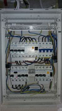
    Hello! The switchgear shown in the photo was made by an electrician. It is located in the attic of the house and supplies the apartment. And here's my question. Reading the forum, I found a few comments about the N wire, which, according to experienced forum users, should go directly to the N rail. For me, the electrician connected this wire first to the 4-pole FRa SD60 100A, with FRa it goes to the RCD and then to the N rail. stay that way, or should I change it e.g. using 3-pole Fra. I have a TN-S 3 phase system. The division of the PEN conductor was made in the main switchboard (connector) at the house. The power from the power plant to my premises is 14 kW. The same electrician installed the main 25A fuse upstream of the meter and a 3-pole SD60 100A fuse downstream the meter in the main switchboard (connector). The second problem is that for now I'm finishing the attic all the time and when I go home I turn off the power with a 16A circuit breaker. After 6 months, the main 3-phase switch, 25A at the bottom, in the main switchgear (connector) tripped. Does anyone know what it could have caused? My guess is that the miniature circuit breaker is not for everyday switching on and off and something rubbed and shorted :) However, thanks to this incident, the question arises what to do to avoid going outside to the main switchboard in the event of a short circuit. I note that the RCD 40A did not work at all then. I greet everyone and wait for an answer. Electrical Switchboard in Attic: N Wire Connection, 4-Pole FRa SD60 100A, RCD, TN-S 3 Phase System
  • ADVERTISEMENT
  • Helpful post
    #2 16480994
    opornik7
    Electrician specialist
    januszl64 wrote:
    Switchboard visible in the photo

    Not a switchboard, but a switchgear.
    januszl64 wrote:
    For me, an electrician connected this wire to a 4-pole FRa first

    I wish you that when maneuvering it, track N always works at the same time as the phase tracks. If it is quicker when disconnecting or late when switching on, you may have problems with live 1-phase devices. The same applies to the 1f circuit powered after the 3 phase RCD (first from left on the upper rail).
    With N rails, the electrician did not go crazy ;) unless the lizard is not finished. I am curious where to connect N from the 1f RCD circuits.
    And where are the overvoltage limiters?
    Where is the reserve in the switchgear for additional devices?
    januszl64 wrote:
    when I go home, I turn off the power with a 16A circuit breaker

    Error. This camera is not intended for this purpose.
    januszl64 wrote:
    what to do to avoid going outside in the event of a short circuit

    Ensure security selectivity.
  • #3 16481073
    januszl64
    Level 8  
    An electrician told me that the surge arrester and the phase controls would "only break". We agreed only to build the main switchgear and the attic one, i.e. WLZ and equip the switchboard. I had to connect the rest myself. And it is so, I think I paid well and now what to pay again. I don't want to call him anymore, I have no nerves for such people. Maybe you have any suggestions :) greetings
  • ADVERTISEMENT
  • #4 16481266
    mawerix123
    Level 39  
    The limiter does not "break" for no reason.

    BTW: two bushings with cables under the 4-pole switch do not bode well.
  • #5 16481306
    Anonymous
    Level 1  
  • #6 16481357
    mawerix123
    Level 39  
    markus-19 wrote:
    I am curious whether the method of cable routing and the ambient temperature, especially in the summer, were taken into account when selecting the protection. Installation of the switchgear in the attic requires little correction as the standard long-term load capacity table is calculated for the temperature of 25 ° C


    Just out of curiosity what values of switches you install in such conditions for 2.5 and 1.5 mm2 wires :?:
  • #7 16481382
    retrofood
    VIP Meritorious for electroda.pl
    opornik7 wrote:

    Where is the reserve in the switchgear for additional devices?

    They already are. Unused.
  • #8 16481393
    Anonymous
    Level 1  
  • #9 16481458
    opornik7
    Electrician specialist
    retrofood wrote:
    They already are. Unused.

    Stach, are you saying that these unconnected cameras are a reserve? ;)
  • ADVERTISEMENT
  • #10 16481462
    retrofood
    VIP Meritorious for electroda.pl
    opornik7 wrote:
    retrofood wrote:
    They already are. Unused.

    Stach, are you saying that these unconnected cameras are a reserve? ;)

    I won't give my head, but I leave it that way. :D
  • #11 16481472
    januszl64
    Level 8  
    Thank you for your interest :) . For 1.5 mm2 wires (lighting) - 10A and for others, i.e. 2.5 mm2 (sockets, washing machine, dishwasher, water heater) - 16A. And I am supposed to have a 7.4 kW induction hob + oven. For this I have a 3-phase 20A fuse inserted by an electrician. I pull the wires myself, also to be on the safe side, under the indium disc. I pulled 5 * 4mm2 (I will use 2 phase from this 20A switch to connect) and a separate 3 * 4mm2 wire (3 phase from 20A switch) to the oven. I am thinking of a little modification to my switchboard. If you can, give me a hint if I am thinking correctly. As there is little space in my switchgear, I thought to remove this 4-pole FR (in the main switchgear at the house there is already a 3-pole meter). Put, for example, a phase indicator in this place, then I will move this 4-pole RCD to it and then just like in the picture. Then I could connect N from WLZ (electrician said that 6mm2 at WLZ is enough) connect immediately to N rail. My plan is that the kitchen and the rest of the apartment should be on a 4-pole 30mA RCD, and the bathroom + lights in the bathroom and kitchen on 1 phase RCD. Both RCDs are at 40A / 30ma. Should I maybe change them to e.g. 20A? The main switch upstream of the meter is 3F at 25A. I know that sometimes there is a problem with helping people like me also a few words about me. I finished the electrical technical college with the rtv specialty rather long ago :) . In Canada, I worked for about a year as an assistant electrician, but it was quite a long time. Now I am thinking of making SEP papers. Also, how can you help it. Greetings.
    ps. unfortunately I haven't done any diagram yet. For now I have everything in my head :)

    Added after 2 [minutes]:

    Of course I realize that differentials must have their own separate N rails to work properly.
  • #12 16481569
    retrofood
    VIP Meritorious for electroda.pl
    januszl64 wrote:
    Both RCDs are at 40A / 30ma. Should I maybe change them to e.g. 20A?

    Don't make eggs!
    Only not 30 mA, but 30 mA.
  • #13 16481587
    Krzysztof Reszka
    Moderator of Electrical engineering
    januszl64 wrote:
    Hello! The switchgear shown in the photo was made by an electrician.

    Why don't I believe it.
    januszl64 wrote:
    I have a TN-S 3 phase system.

    januszl64 wrote:
    Then I could connect N from WLZ (the electrician said that 6mm2 at WLZ is enough) connect immediately to the N bus

    It is in WLZ that the PEN division has already been completed. Where are the equipotential bonding. PE conductor grounded or not.
    Buddy, give me a diagram of this installation, it will be easier to write.
    https://www.elektroda.pl/rtvforum/topic2053101.html
    Helpful material here.
    https://www.elektroda.pl/rtvforum/topic3263074.html
  • #14 16481650
    elpapiotr
    Electrician specialist
    januszl64 wrote:
    I pull the wires myself, also to be on the safe side, under the indium disc. I pulled 5 * 4mm2 (I will use 2 phases from this 20A switch to connect) and a separate 3 * 4mm2 wire for the oven (3 phase from a 20A switch)

    Even if the oven is equipped with a 230 V plug?
  • ADVERTISEMENT
  • #15 16481861
    januszl64
    Level 8  
    I didn't press that key, of course 30mA.
    I also expected more from someone who charges PLN 700 for 4 hours. I just have an invoice signed, also if someone does not believe that the switchgear was made by an electrician with permissions, I serve a copy.
    Returning to technical matters, as I wrote, I am not a professional and I did not do it, but as far as I know, the cable that comes to the main switchboard from the network has 4 wires, i.e. 3 phases and one wire acting as a neutral and protective conductor, i.e. TN -C. It was written in the grid connection conditions that the system should be changed to TN-S. And the electrician showed me that he did it in the main switchboard. From there, this WLZ (I think it is called) goes to the attic - about 8 meters diagonally.
    If the oven will be equipped with a plug, I was just going to insert a socket in the wall and connect this 3 * 4mm2 cable to it.
    The scheme as I wrote, unfortunately, I did not have time to do it, and the electrician who did this job did it out of his head.
    Oh, the PE conductor is definitely grounded in the main switchboard. I remember asking an electrician if he could take a grounding test, but he didn't have a meter with him, at least that's what he explained.
    Is there any simple graphic program to make such a switchgear diagram?
    Greetings.
  • #16 16481937
    Akrzy74
    Rest in Peace
    januszl64 wrote:
    or should i change it
    januszl64 wrote:
    was made by an electrician

    If a colleague wants to change something on his own, why did he hire an electrician?
    There is no simple switchgear design program, because you need design knowledge or forum literature (for simple switchgears). What is your friend expecting now?
  • #17 16481941
    Krzysztof Reszka
    Moderator of Electrical engineering
    januszl64 wrote:
    Is there any simple graphic program to make such a switchgear diagram?

    After all, I gave the bearings.
    januszl64 wrote:
    I remember asking an electrician if he could take a grounding test, but he didn't have a meter with him, at least that's what he explained.

    Call in another person with a certificate of qualification for electric shock protection measurements.
  • #18 16481951
    Akrzy74
    Rest in Peace
    Krzysztof Reszka wrote:
    Call in another person with a certificate of qualification for electric shock protection measurements.

    The certificate is not enough, you need a measuring device and a willingness to perform such a measurement, because I think everyone who has an "installer" company has such qualifications. For the principle (stamps)? :wink:
  • #19 16482072
    januszl64
    Level 8  
    Thanks for the help and links. Greetings.

Topic summary

The discussion revolves around the installation and configuration of an electrical switchboard in an attic, specifically addressing the connection of the N wire in a TN-S 3 phase system. The user questions whether the N wire should connect directly to the N rail instead of going through a 4-pole FRa SD60 100A circuit breaker before reaching the RCD. Forum participants emphasize the importance of ensuring that the N wire operates synchronously with the phase wires to avoid issues with single-phase devices. Concerns are raised about the adequacy of the installation, including the need for surge protectors, proper cable routing, and temperature considerations in the attic environment. Suggestions include modifying the switchboard layout for better space management and ensuring compliance with safety standards. The user also discusses the installation of various circuit breakers for different wire sizes and appliances, including a 7.4 kW induction hob and other household devices.
Summary generated by the language model.
ADVERTISEMENT