logo elektroda
logo elektroda
X
logo elektroda

Should the disconnector in the switchboard also disconnect the N line ?

pqma 13035 19
ADVERTISEMENT
Treść została przetłumaczona polish » english Zobacz oryginalną wersję tematu
  • #1 14572494
    pqma
    Level 13  
    Question as per topic ...

    And it came about in the fact that when I look at my (2) switchboards the disconnectors are only on the phases (FR 103) and the N wire is not disconnected.

    And when I look at various examples it is rather that all conductors are disconnected, except PE of course (using FR 304 for example).

    The power supply to the building is TN-C-S, which to the best of my (poor) knowledge means that the PEN distribution is in the ZK outside the building, the building/distribution boards are therefore supplied with 5 core cable.
  • ADVERTISEMENT
  • Helpful post
    #2 14572575
    zdzisiek1979
    Level 39  
    Some do it this way others do it that way :D in order to disconnect N the disconnector must have this option and more specifically the N track must have a delay in disconnecting N and an advance in switching on the N track then the risk of asymmetry and damage to consumers is eliminated.
    In my opinion, there is no need for N disconnection and you can theoretically save one field in a row. In addition, I disregard the fact that the possibility of N loosening in the terminal will, for one thing, burn out the disconnector and, for another, asymmetry may occur (two terminals two weak points along the N path).
  • #3 14572643
    pqma
    Level 13  
    That is, as I understand it, it is good and even better.

    Thanks!
  • #4 14573099
    gogi20
    Level 24  
    I have the same opinion as "zdzisiek1979". It has never yet occurred to me to "pass" N through FR. "Passing" N through the FR is, however, also an acceptable option, provided that the FR has a dedicated N track (3P+N) just as colleague "zdzisiek1979" mentioned.
  • #5 14573141
    pqma
    Level 13  
    If you're so kind, I'll expand my question to include whether it would be possible to somehow reduce the number of modules used to connect the two switchboards (I'm running out of space to put in the automation so every module counts).

    The connection is 3F and currently it is implemented so that in the main one there is Ska wide for 3 modules and in the second FR also for 3 modules.

    Do you perhaps know of a solution (e.g. 2 module) to connect these switchboards correctly ? I've seen somewhere that people sometimes do without this Ski in the main, but I think that's overkill.
  • ADVERTISEMENT
  • Helpful post
    #6 14573156
    zdzisiek1979
    Level 39  
    I am not familiar with the methods. A distributor should always be selected with an allowance for the future, but probably more for the convenience of installation. If it is selected to fit, or if it is too big/expensive, this will pay off in time.
  • ADVERTISEMENT
  • #7 14573159
    pqma
    Level 13  
    He just got his revenge, although I was unfortunately not asked by anyone if I wanted a spare ...
  • #8 14573164
    gogi20
    Level 24  
    With something like that, it's off to the fortune teller:) This "main eska" is probably the protection for the cable to the second distribution board? The FR in the second switchboard will not be eliminated. You can always replace the switchgear, although that's a cost and quite a lot of work (certainly more than installing a switchgear with a spare right away:) ). Alternatively, a separate switchboard could be set aside for the 'automation'.
  • #9 14573168
    Anonymous
    Anonymous  
  • #10 14573180
    pqma
    Level 13  
    Well, yes with this Ska you are right ...

    The switchboard is 3x12 clogged 100%. I've even already bought a second one for the automation, but I'm thinking of replacing the switchgear with a bigger one. I'm afraid, however, that it will turn out, for example, that some of the wires/cables are physically cut too short and there will be a problem with connecting circuits ...

    Is it possible to solve this somehow? What to do if 15cm of wire from one of the circuits is missing ? I can't imagine too much hoeing, unless it can be done safely and legally ...

    Added after 2 [minutes]:

    Bronek22 wrote:
    a diode jumper should be placed on the N contact of the RCD - so that the RCD does not make a break in the N.
    .

    And does it do ?? I don't know, I don't know. Maybe it only interrupts the phase ?

    Sorry, I read it disconnects all :) .
  • #11 14573192
    elpapiotr
    Electrician specialist
    pqma wrote:
    Can this be solved somehow ? What if 15cm of wire is missing from one of the circuits ? Somehow I can't imagine too much hoeing, well unless it can be done safely and legitimately ....
    .
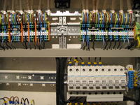
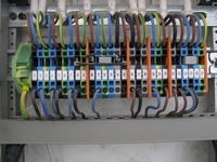
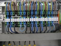
    Surely there will be no shortage if, for example, such badges are used -.

    Should the disconnector in the switchboard also disconnect the N line ? .
  • ADVERTISEMENT
  • #12 14573198
    pqma
    Level 13  
    elpapiotr wrote:
    .
    Certainly there will be no shortage if, for example, such badges are used -

    .

    But lovely, what is it called ? Are there any other patents of this type ??

    I would like to have so much space in the switchboard :(
  • Helpful post
    #13 14573200
    gogi20
    Level 24  
    Bronek22 wrote:
    gogi20 wrote:
    I have the same opinion as "zdzisiek1979". It has never yet occurred to me to "let" N through FR. "Passing" N through the FR is, however, also an acceptable option, provided that the FR has a separate N path (3P+N) as colleague "zdzisiek1979" mentioned.
    Conclusion from your statements - in every installation where there is one 3-f RCD for the whole, on the N contact in the RCD there should be a diode jumper - so that the RCD does not make a break in the N.
    The conclusion is that one 3-f RCD for the whole is a mistake in art and there is nothing to discuss how to patch it. This is simply not how it should be done.
  • Helpful post
    #14 14573207
    elpapiotr
    Electrician specialist
    pqma wrote:
    I would like to have that much space in the switchboard
    .
    Then you have to use a switchboard with 80 fields, there will be space.
    And then it is done like this :

    Should the disconnector in the switchboard also disconnect the N line ? Should the disconnector in the switchboard also disconnect the N line ?
  • #15 14573210
    pqma
    Level 13  
    elpapiotr wrote:
    .
    Then you have to use a switchgear for 80 fields, there will be space.


    My wife would probably kick me out of the house,and certainly out of the pantry where this switchboard is ....

    Although a friend of mine who is just building a house has put two automation cabinets the size of a very large fridge inside ... now I know why ...

    Added after 2 [minutes]:

    gogi20 wrote:
    The conclusion is that one 3-f RCD for the whole thing is a malpractice and there is nothing to quibble about how to patch it. This is simply not the way it should be done.


    This worried me even more mate because it was supposed to be one of the solutions to the lack of space .... and a mistake by the electrician because there are no RCDs on all circuits where they should be ....

    Added after 10 [minutes]:

    But on the other hand, I don't think it matters whether it's an RCD for the whole building or for one circuit (multiple RCDs).
    The scale is different but the problem of order of N disconnection can always arise.
  • #16 14573219
    Anonymous
    Anonymous  
  • #17 14573244
    pqma
    Level 13  
    Bronek22 wrote:
    The problem of N disconnection is only in the WLZ or 3-phase cable.
    .

    So you don't recommend serving the whole sub-distribution board from one 3F RCD (main also 3F of course, cable between them 5 wires)?
  • Helpful post
    #18 14573892
    Anonymous
    Anonymous  
  • #19 14573932
    pqma
    Level 13  
    The issue of the 3F RCD relates to the second smaller sub-distribution board in the basement.
    There is more space there, and I can freely insert a 3F RCD instead of a Ski in a 3F socket on the wall that is never used (disconnect the socket).

    The problem with the basement is that the pump and the thermo are without RCD (the installation was supposedly professional, but 15 years ago), and the manufacturers of both recommend and even condition the warranty on this. I will not add that, for example, when pouring water into the pump, it pees left and right, and the basement itself can be slightly damp etc. etc. ... As I wrote the power supply of the building is TN-C-S.
  • #20 14574354
    kkas12
    Level 43  
    Zero input.
    To start with, I would suggest PN HD 60364 4-41. It is concerned with electric shock protection.
    Secondly, PN HD 60364 5-54, which is about equalisation connections.
    Finally, sheet 7-701 concerning bathrooms.
    In addition, studies by Dr. Musial.

    Apart from the content of the mentioned sheets as well as the works of Dr. Musial, I would like to inform you that everything you are asking has been repeatedly and thoroughly discussed on this and other forums.
    So I would very much like to ask my colleague to get rid of the claiming attitude and put a minimum of your own work into your topics.
    This is because there is a point in the rules:
    3.1.17. It is forbidden to publish posts which lower the general level of discussion, which are the result of laziness or which contain a demanding attitude.
    on the edge of which a colleague nonstop balances.

Topic summary

The discussion revolves around whether the disconnector in a switchboard should also disconnect the neutral (N) line. Participants express differing opinions on the necessity and implications of disconnecting the N line. Some argue that disconnecting the N line can prevent asymmetry and potential damage to consumers, while others believe it is unnecessary and can complicate the installation. The conversation also touches on the configuration of switchboards, specifically the use of 3-phase (3F) RCDs and the challenges of space in switchboards. Suggestions include using dedicated N tracks in disconnectors and considering the future expansion of installations. The importance of adhering to electrical standards and regulations is emphasized, with references to specific standards for electric shock protection and equalization connections.
Summary generated by the language model.
ADVERTISEMENT