logo elektroda
logo elektroda
X
logo elektroda

Review and Feedback on Single-Family House Switchboard Design: Phase Separation and Protection

elektro_dom 61770 44
ADVERTISEMENT
Treść została przetłumaczona polish » english Zobacz oryginalną wersję tematu
  • #1 16903004
    elektro_dom
    Level 7  
    Hello,

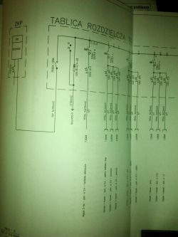
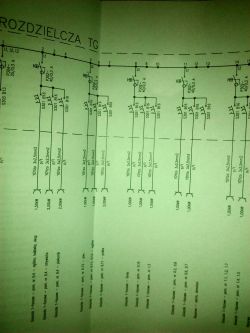
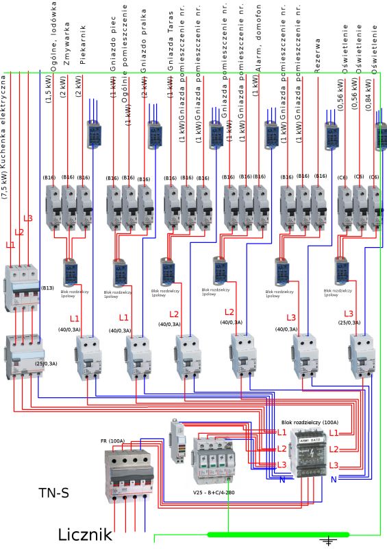
    I would like to ask honorable users to comment on this installation of a switchboard for a single-family house. In the subject of electrical circuits, I will not only enter, please, comment on the box itself, phase separation and protection.
    Well, this is the design of my electrical installation made by a designer. For ease of use for myself I switched the diagram to a version that is easier to digest. Please check if the diagram agrees with the graphic version.

    Personally, I think that the designer exaggerated with the number of differentials ...

    Is the surge voltage connected to the distribution block as shown?


    Thanks in advance to everyone for your help
    Review and Feedback on Single-Family House Switchboard Design: Phase Separation and Protection Review and Feedback on Single-Family House Switchboard Design: Phase Separation and Protection Review and Feedback on Single-Family House Switchboard Design: Phase Separation and Protection
  • ADVERTISEMENT
  • Helpful post
    #2 16903020
    mawerix123
    Level 39  
    Why do you need these distribution blocks on the phase conductors between the RCD and the circuit breakers :?: such a connection is made with a single-phase comb.

    The main switch 4P is incorrect and introduces a hazard.

    How to understand it on the C16 and in B13 in brackets :?: So you have designed the C6A for lighting :?:

    I think the SPD is out of the box.

    What is the layout of the supply network :?:
  • Helpful post
    #3 16903036
    kkas12
    Level 43  
    Why an RCD in the cooker, intercom and alarm circuit? Will the protection against electric shock be insufficient without this apparatus? Sheet 4-41 says otherwise.
    Why RCDs in lighting circuits? After all, no standard except 7-701 requires them except 7-701. However, it only applies to bathrooms.
    Why a distribution block between the RCD and the miniature circuit breaker. It is just a superfluous gadget that generates costs and takes up space. There are, after all, comb rails.
    The FR (four-line) is completely unsuitable for use as a main switch, and breaking the N track in the TN system at this point is an unjustified whim that can turn out to be costly.
  • #4 16903040
    elektro_dom
    Level 7  
    mawerix123 wrote:
    The main switch 4P is incorrect and introduces a hazard


    I understand it should only be on phase without N? - so the designer made a mistake?

    mawerix123 wrote:
    How to understand it on the C16 and in B13 :?: So you have designed the C6A for lighting


    In black brackets there are values designed by the designer, but I have not erased the values from the cameras and they are misleading, so please pay attention only to the values added to the cameras.
  • Helpful post
    #5 16903050
    mawerix123
    Level 39  
    elektro_dom wrote:
    so the designer made a mistake?


    Yes, without N or 3P + N and not 4P, often repeated error.

    This B13A replace B16A easier to access C6A is for some special reasons :?: typically B10A is used

    You did not provide the power supply system and the pre-meter protection, it may be necessary to protect the voltage presence indicators.
  • #6 16903093
    elektro_dom
    Level 7  
    kkas12 wrote:
    The FR (four-line) is completely unsuitable for use as a main switch, and breaking the N track in the TN system at this point is an unjustified whim that can turn out to be costly.


    I understand that you need to use a three-track? designer error?

    And is the connection between the overvoltage and the distribution block (100A) correct? Is it necessary to somehow connect the surge voltage with the phases on a separate connector before the distribution block?
  • ADVERTISEMENT
  • #7 16903119
    kkas12
    Level 43  
    I would have given WG an overload switch for the stove, connected these devices with a rail, and from under the terminals of one I would lead the wires to the block, and from the other to the lightning arrester (limiter).
    Of course, this rail will also connect the protections of those circuits that are not required by RCDs, i.e. intercom, alarm, lighting. Apart from the bathroom, the lighting of which I would secure P312 B10 or B6.

    In addition, the division of the PEN in the connector and the power limiting protection in the form of an overload switch also makes no sense.

    And for the stove, I suggest 5x4mm2.

    And whether it is a designer's error does not matter to me. I take it as a malpractice.
  • #8 16903133
    elektro_dom
    Level 7  
    mawerix123 wrote:
    This B13A replace B16A easier to access C6A, for some special reasons B10A is usually used


    Thanks a lot for your feedback, I will keep that in mind! I have already asked this question to another interlocutor, but I will also ask you. Please write if it is appropriate to connect a storm surge voltage switch to a distribution block? shouldn't it be connected to the phases on separate connectors before the distribution block?

    mawerix123 wrote:
    You did not provide the power supply system and the pre-meter protection, it may be necessary to protect the voltage presence indicators.


    Pre-meter protection S303C25, but I can add a lamp protection, hymm only of what value?
  • Helpful post
    #9 16903156
    elpapiotr
    Electrician specialist
    On the other hand, I would give a distribution block for WG, and from it I would take outlets for individual apparatuses, taking into account also the so-called "combs".
    This also applies to surge arresters.
  • #10 16903157
    mawerix123
    Level 39  
    elektro_dom wrote:
    Please write if it is appropriate to connect a storm surge voltage switch to a distribution block?


    So far, it is not known whether this "storm surge" will survive the storm :D I would care more than where it is plugged in. How, where and with what cross-sections of the cables are specified by the SPD manufacturer.

    In your diagram, the SPD is ambiguous because the symbol is a spark gap and the varistor type ... is typical.

    Next, you flash from the type of the supply network and it is important when choosing an SPD whether it is a cable or overhead power supply, as well as whether it is a lightning protection system.

    elektro_dom wrote:
    hymm only of what value?


    The most commonly used is, for example, S303 B6A
  • Helpful post
    #11 16903321
    kkas12
    Level 43  
    elpapiotr wrote:
    This also applies to surge arresters.

    Yes, but on condition that they are "powered" from the bottom and have the width of a module.
  • Helpful post
    #12 16903491
    emigrant
    Level 29  
    elektro_dom wrote:
    Please write if it is appropriate to connect a storm surge voltage switch to a distribution block?

    Unless the SPD has double clamps for the V system or you do not want to use it, you connect it directly to the distribution block by the shortest possible route. While it is true that TN-S comes to the RG, you are buying a 4-pole 4 + 0 or 3 + 1 SPD.
  • #13 16904124
    elektro_dom
    Level 7  
    mawerix123 wrote:
    Next, you flash from the type of supply network and it is important in the selection of SPD whether it is a cable or overhead power supply, as well as whether it is a lightning protection system.


    So I give it, and I can see that there is a big error in the diagram at the lightning arrester ... and there is no separation between PE and N

    TN-C network

    connected load 12 kW

    earth line, YAKXs 4x120mm cable connection
  • ADVERTISEMENT
  • #14 16904191
    kkas12
    Level 43  
    After all, the PEN was split in the cable joint. This is a legal malpractice :)
  • #15 16904206
    elektro_dom
    Level 7  
    emigrant wrote:
    Unless the SPD has double clamps for the V system or you do not want to use it, you connect it directly to the distribution block by the shortest possible route. While it is true that TN-S comes to the RG, you are buying a 4-pole 4 + 0 or 3 + 1 SPD.


    It is different, sorry for the confusion

    TN-C network

    connected load 12 kW

    earth line, YAKXs 4x120mm cable connection


    Then PEN separation necessary? and I understand that if you connect a lightning arrester in a distribution block, it should be the shortest route directly at the phase inputs from the WG
  • #16 16904212
    emigrant
    Level 29  
    TN-C comes to the switchboard? Otherwise, how many cores in the cable reach the switchgear?
  • ADVERTISEMENT
  • #17 16904226
    kkas12
    Level 43  
    emigrant wrote:
    TN-C comes to the switchboard? Otherwise, how many cores in the cable reach the switchgear?
    After all, everything is drawn in the first post.
  • #18 16904235
    elektro_dom
    Level 7  
    emigrant wrote:
    TN-C comes to the switchboard? Otherwise, how many cores in the cable reach the switchgear?


    Well, in the diagram and in the drawing, there are 5 wires to the WG, and in the conditions I have a cable connection cable 4-wire 4x120 mm
  • #19 16904244
    kkas12
    Level 43  
    4x120 cable for the connector. This is not your plot.
    What matters from the connector / meter to the building. And here you and the 5x designer drew.
  • #20 16904250
    emigrant
    Level 29  
    Can you not verify this physically? Papers with papers ... In addition, you can throw these papers in the trash. RCD 300 mA inserted everywhere, some distribution blocks for RCD, FR 4P.
  • #21 16904268
    Anonymous
    Level 1  
  • #22 16904340
    emigrant
    Level 29  
    kkas12 wrote:
    After all, the PEN was broken in the cable joint. This is a legal malpractice :)


    What will you do if someone built a house on a foundation slab? Foundation earth electrode completely insulated from earth with polyester XPS. The house does not have a lightning protection system, so you do not need a ring earth electrode and connecting both earth electrodes. TN-C connected to the switchgear. Is the PE rail (PEN) to be earthed to the foundation earth electrode isolated from earth?
  • Helpful post
    #23 16904353
    Anonymous
    Level 1  
  • #24 16904547
    elektro_dom
    Level 7  
    emigrant wrote:
    Can you not verify this physically? Papers with papers ... In addition, you can throw these papers in the trash. RCD 300 mA inserted everywhere, some distribution blocks for RCD, FR 4P.


    Well, it is better to ask and find out something than to wade further, listen at my construction site, the situation is that the network is connected to the ground from the transformer to the box on the border of my plot and so far that's all (I do not have a connection from the house to the box) :) I know that now I have to bring the cable from the box to the house to the switchboard and in the project behind the meter to the WG there are 5 wires. What is before and what should be unknown, I do not have a connection project (from the box in the border to the house) ...
  • #25 16904553
    retrofood
    VIP Meritorious for electroda.pl
    elektro_dom wrote:
    listen at my site, the situation is that the network is connected to the ground from the transformer to the box on the border of my plot and so far that's all (I do not have a connection from the house to the box)

    Have you made an earth electrode?
  • #26 16904581
    elektro_dom
    Level 7  
    I have important questions ...

    1. Storm lightning

    for lack of knowledge, I did not lead the hoop from the foundation reinforcement ...

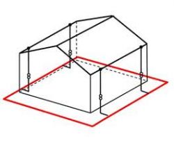
    so I thought about the matter and dug the hoop around the house (about 2 m from the walls to a depth of about 90 cm raised up at four points)
    Review and Feedback on Single-Family House Switchboard Design: Phase Separation and Protection
    , I haven't connected it yet and I don't know because some people say to weld and some advise to screw them together and paint the joints with dispersite. Please write how is it correct?


    2. Earthing

    I do not have an earth electrode for the future electrical installation at all ... what to do now in an open shell? pierce a concrete floor and stick a pin under the future electrical box away from the lightning bolt? or join the lightning bolt but I think it's suicide? whether to state that it is unnecessary because the cable from the connector has PE after all? - (I prefer to have some minimum knowledge when discussing with an electrician :)
    I am asking for power !!! thanks in advance! :)

    Added after 6 [minutes]:

    elektro_dom wrote:
    # 26
    retrofood wrote:
    Have you made an earth electrode?


    and here's the question ... # 26 , thanks for the help...
  • #27 16904643
    kkas12
    Level 43  
    It is necessary to connect to the earth electrode and lead the hoop on the wall near the switching station. The connection must be made underground, then it will not be suicide.
    You can weld, but the welds must be protected against corrosion.
  • #29 16904956
    elektro_dom
    Level 7  
    kkas12 wrote:
    It is necessary to connect to the earth electrode and lead the hoop on the wall near the switching station. The connection must be made underground, then it will not be suicide.
    You can weld, but the welds must be protected against corrosion.


    thanks a lot ... I have a question about the performance connection itself and I understand that it must be as short as possible between the distribution box and the rim around the foundations,

    the distance between the planned inside switch box and the rim around the foundations outside the building is 4 m.

    AND WAY
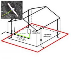
    Can I run a 16 mm2 copper cable from the box and connect it to a hoop iron in the ground outside the building, whereby the cable must be placed on the spout under the polystyrene as shown in the picture:

    Review and Feedback on Single-Family House Switchboard Design: Phase Separation and Protection

    WAY II
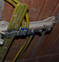
    can he not connect the copper cable in the ground, but only put the hoop on the inner wall from the outside and from there, on the spout under the polystyrene to the rail to the box, with a 16mm2 copper wire, except that it would probably be necessary to secure this rail with a hoop iron
    cover? picture:

    Review and Feedback on Single-Family House Switchboard Design: Phase Separation and Protection

    WAY III
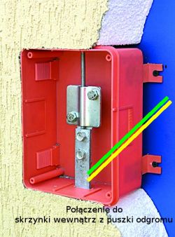
    to connect in a lightning protection box? picture:

    Review and Feedback on Single-Family House Switchboard Design: Phase Separation and Protection

    And in general, can I run the cable under the polystyrene on the spout - an insulated copper cable in the vicinity of the connection cable?


    thanks for the help !!!
  • Helpful post
    #30 16905086
    elpapiotr
    Electrician specialist
    The third way is out, and this is what a colleague wrote about kkas12 .

Topic summary

Discussion focused on the design and installation of a switchboard for a single-family house, emphasizing phase separation and protection mechanisms. Users raised concerns about the excessive use of residual current devices (RCDs) in circuits, the appropriateness of distribution blocks between RCDs and circuit breakers, and the correct connection of surge protective devices (SPDs). The necessity of separating the neutral (N) and protective earth (PE) conductors in a TN-C system was debated, along with the proper grounding techniques and the installation of lightning protection systems. Suggestions included using comb rails for connections and ensuring that SPD connections are as short as possible to minimize voltage surges. The importance of adhering to electrical standards and safety regulations was highlighted throughout the discussion.
Summary generated by the language model.
ADVERTISEMENT