logo elektroda
logo elektroda
X
logo elektroda

Berker LAN Socket Connection: Steps for Properly Connecting Wires with Knife Clamps & Insulation

babarek 42759 4
ADVERTISEMENT
Treść została przetłumaczona polish » english Zobacz oryginalną wersję tematu
  • #1 14701693
    babarek
    Level 13  
    Hello

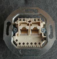
    How to properly connect the wires to the socket as in the photo

    Berker LAN Socket Connection: Steps for Properly Connecting Wires with Knife Clamps & Insulation

    I understand that there are knife clamps in the socket and you only need to push the wire in without stripping the insulation?
  • ADVERTISEMENT
  • #2 14701723
    PiotrPitucha
    Level 34  
    Hello
    As you can see in the photo, you have colored contacts in the socket, you connect color to color and that's the whole philosophy.
    It can be confusing that there are too many colors, but notice that you still have the letters A and B.
    The colors on the upper part of the bar are for the T-568B connections and the lower ones for the T-568A, it is up to you which one you choose, the type of connections should be identical on both sides of the cable, although modern equipment will cope if you are not consistent.
    greetings
  • ADVERTISEMENT
  • #3 14701911
    hermes-80
    Level 43  
    As you can see, the colors are beyond the standards - UTP - it's best to take a multimert (light bulb with a battery, ohmmeter, buzzer) and set the cable connection to the standard you have in the network.
  • ADVERTISEMENT
  • #4 14703453
    babarek
    Level 13  
    I will connect as Piotr suggests, according to the connections of T-568B.

    Upper clamps order from left:
    Brown
    White-brown
    White and blue
    blue
    green
    white-green
    orange
    white-orange

    Lower clamps from left:
    Brown
    White-brown
    White and blue
    blue
    green
    white-green
    orange
    white-orange

    I think it should be OK
  • #5 14883312
    babarek
    Level 13  
    I set up category 5 sockets. On the other hand, I tightened the pins that will go to the switch. Wire pair connections checked with an inexpensive tester from the auction site. Everything Ok.
    However, I have a problem with the additional socket that was supposed to be used as a telephone socket. Berker UAE 8-pole Cat.3
    The socket looks like the picture, only it is single. In the upper part of the socket there are numbered terminals where the wires are tightened with screws. From right to left we have 1,2,3... to 8.
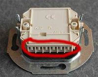
    Berker LAN Socket Connection: Steps for Properly Connecting Wires with Knife Clamps & Insulation

    Berker LAN Socket Connection: Steps for Properly Connecting Wires with Knife Clamps & Insulation

    I installed all plugs and previous sockets in accordance with the T568B standard.

    Berker LAN Socket Connection: Steps for Properly Connecting Wires with Knife Clamps & Insulation

    Here I also did so, connecting according to the diagram:
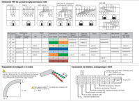
    Berker LAN Socket Connection: Steps for Properly Connecting Wires with Knife Clamps & Insulation

    To clamp 1: white-orange, to clamp 2: orange, to clamp 3: white-green and so on.

    The problem is that the tester does not light up when checking it as if there were no pairs connected. I think I connected the cables correctly? Maybe I am wrong and there is a mistake.
    Now all I can think of is to ring the wires in the twisted pair and check for continuity.
ADVERTISEMENT