logo elektroda
logo elektroda
X
logo elektroda

Bosch AL1820CV Damaged Li-Ion Charger: Repairing After Faulty Electrical Connection

farel123 39147 21
ADVERTISEMENT
Treść została przetłumaczona polish » english Zobacz oryginalną wersję tematu
  • #1 15743450
    farel123
    Level 12  
    Hi
    I got a Bosch AL 1820 CV model charger. I want to use it for new high-current cells that I have at the moment and when the charger is successfully repaired, I will probably put them into a Hitachi screwdriver.
    This charger was reportedly connected to a faulty electrical system, where there was phase-to-phase current. The 30 ? resistor, the 47 uF / 400 V capacitor and the 1.25 A slow-blow fuse were burnt.
    After replacing the elements with new ones, when connected, the fuse burns and breaks the security in the house. It turns out that when there is a switch on the fuse, there is a short circuit at the 230 V input. I am a beginner in electronics, but I have a good meter and I can rather take a measurement.
    I don't take pictures because you can't see anything there, but the charger looks the same as this one: Link
    What else can I check, apart from the three elements that I replaced with new ones?
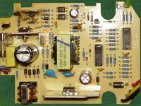
    Bosch AL1820CV Damaged Li-Ion Charger: Repairing After Faulty Electrical Connection Bosch AL1820CV Damaged Li-Ion Charger: Repairing After Faulty Electrical Connection
  • ADVERTISEMENT
  • #2 15743705
    ArturAVS
    Moderator
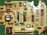
    Rectifier diodes next to the capacitor, and a transistor (it looks more like a TOP) on the heat sink.
    First, desolder this transistor (TOP) and check if the fuse is still on. Enter the designations.
  • #3 15747814
    farel123
    Level 12  
    I checked the diodes, the rectifiers were damaged, I replaced them with the same ones and there is no short circuit. With a quick movement of my hand, I plugged it into the socket for a fraction of a second and the 30 ? resistor, which I was replacing, started to burn. I soldered this TOP transistor near this resistor, it has the designation F3NK80z.
    How can I check it?
  • ADVERTISEMENT
  • #4 15748321
    ArturAVS
    Moderator
    It's a regular mosfet. Check that there is no breakdown between the source and the drain. Middle stand to the right (looking from the inscription).
  • #5 15749463
    farel123
    Level 12  
    There is no puncture between the source and the drain, and there is no breakthrough between the rest of the pins.
    Resistance of 0.88 k? between gate and drain, between gate and source 4.38 M?, drain and source 4.38 M?.
    What else can I check? Maybe one of those little transistors?
    KT503, what to measure?
  • ADVERTISEMENT
  • #6 15750185
    ArturAVS
    Moderator
    Did you measure desoldered or on the disc?
    If it is desoldered, it is damaged. Check KT503 too. When running in series with the power supply, give a 60 W bulb, it will protect against further damage.
  • #7 15762358
    farel123
    Level 12  
    Sorry for the delay, but I only play with it when I'm really free.
    I measured the F3NK80z desoldered, why is it damaged?
    For me, however, it is not KT503, but 2N3904, there is a transition between the collector and the emitter, there is no other pins. Does that mean it's broken too? I will probably not get this 2N3904 at my store, so I can use a popular replacement, for example BC546, because I have one?
    There is also this LED: STTH602C datascheeat:
    http://www.st.com/content/ccc/resource/techni...ea/47/cb/CD00110348/files/CD00110348.pdf/jcr: content / translations / en.CD00110348.pdf how to check it?
  • #8 15762889
    ArturAVS
    Moderator
    The diode is double. You check like a regular one. One way it is supposed to lead, and the other way it is not.
    For each single diode included in the STTH602 structure, you need to take measurements.
    Instead of the 2N3904, you can use a replacement.

    There should be no resistance between the gate and the drain. Check in both directions.
  • #9 15763936
    farel123
    Level 12  
    The F3NK80z diode is ok.
    Instead of 2N3904 I will give BC546.
    Can I also replace n-mosfet F3NK80 with some other for testing?
    From what I read on foreign forums, if I look for it, maybe I'll find something.
  • #10 15763993
    ArturAVS
    Moderator
    There may be a problem with the replacement F3NK80Z.
  • ADVERTISEMENT
  • #11 15777312
    farel123
    Level 12  
    It is, the F3NK80Z replaced with a new one and the 2N3904 with the BC546, the 30R resistor is also new.
    When connected in series to the power input of a 100 W bulb and connected to the mains, there are no effects, the bulb does not even blink, the diode in the charger is also off. I measured the voltage at the charger output, there is some 1 V between the cables.
    Now what, unplug the bulb and try without it, is there still something wrong?
    Tomorrow I will measure the voltage at the output of such a charger without load.
  • #12 15785611
    farel123
    Level 12  
    A working charger has a voltage of 5 V at the outputs.
    How with this bulb is connected in series, the device is still to work normally if it is functional?
  • #13 15786658
    ArturAVS
    Moderator
    Yes, it is supposed to work. Except that the light bulb acts as a current limiter.
  • #14 15787152
    farel123
    Level 12  
    So it doesn't work. There is no short circuit now, nothing is hot, I do not know if sometimes it is not this chip 07502233 that is damaged, will it be able to somehow replace it or at least check it?
    This is also the LM324AN chip, can it be checked somehow? Like something, I have an LM324A (without an N at the end) on some PCB for recovery.

    Here is some topic: http://www.eevblog.com/forum/repair/bosch-10v-charger-repair/
  • #15 15787434
    ArturAVS
    Moderator
    Draw the schematic from the original side of the inverter. After the connection layout, you can find out what it is.
  • #16 15801750
    farel123
    Level 12  
    I found a diagram here: https://obrazki.elektroda.pl/6889151000_1344107748.jpg someone was already drawing it, I processed half of it and that's right, if I need to, I can make it clearer and describe the elements.
    Diagram from the topic: https://www.elektroda.pl/rtvforum/topic2345057.html#11175933

    They write something here again, with the help of chrome I could read something (right click, "translate into Polish"): http://www.teleservice-depannage.com/t9125-Probleme-de-resistances-grillees-sur-BOSCH- AL-1115-CV.htm on the other side is kind of a solution.
    I managed to check the resistor from those that the guest writes is damaged, but its value does not suit me. The strips (5 pieces) red, purple, black, silver, brown come out in 2.7 ?, where they say 3.3 ? or 3.6 ? on these forums. I can give 3 ohms because I can't find 2.7 ohms?

    And as for this bulb, it can be at the very input after powering from the mains, or in series with the fuse on the board?
  • #17 15839743
    farel123
    Level 12  
    The charger is lit, the voltages are rather ok, on the two 5 V contacts on the third it is different. I need to check if it is charging on the battery.

    The question now is whether there is an option to charge Samsung ICR 18650 22P (3.7V / 2150mAH / 10A) cells with it. Charging them is standard for Li-Ion 4.2 V. Is it better not to combine and buy a charger with a balancer?
  • #18 15859249
    farel123
    Level 12  
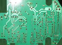
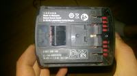
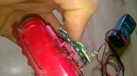
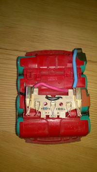
    The charger is charging, something squeaks (probably a transformer), but it works. The Bosch battery is 14.4 V, the cells are probably 18650-13q 1.3 Ah (after charging with a Bosch charger, a single cell is about 4.1 V, the battery is about 16.4 V), the nominal voltage for these cells is 3.6 V For my ICR 18650-22P it is 3.7V, but the charging voltage is the same for both, only the max charging current for 13q is 4A and for 22P it is 2.15A

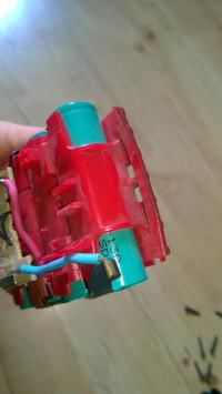
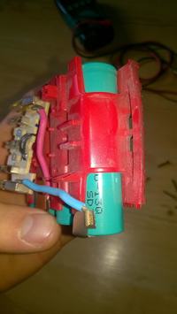
    I also have a question about the protection against over-discharge of the battery, I thought that there was a special circuit in the battery responsible for this, when I dismantled it, I noticed the lack of something like this. How can it be made, electronics in a screwdriver?
    Bosch AL1820CV Damaged Li-Ion Charger: Repairing After Faulty Electrical Connection Bosch AL1820CV Damaged Li-Ion Charger: Repairing After Faulty Electrical Connection
    Bosch AL1820CV Damaged Li-Ion Charger: Repairing After Faulty Electrical Connection Bosch AL1820CV Damaged Li-Ion Charger: Repairing After Faulty Electrical Connection Bosch AL1820CV Damaged Li-Ion Charger: Repairing After Faulty Electrical Connection
  • #19 15859275
    Strumien swiadomosci swia
    Level 43  
    Yes, the screwdriver has the processor and the rest of the control.
  • #20 16298122
    MeloSeb
    Level 13  
    Hello, I would like to continue the topic.
    I have an identical charger and a similarly damaged one. I have replaced the elements marked in the drawing, but unfortunately they are damaged again when connected to the power supply. All in all, this capacitor, a large electrolyte, has already been replaced, but it is rather functional. Can you advise me something else?
    Bosch AL1820CV Damaged Li-Ion Charger: Repairing After Faulty Electrical Connection
  • #21 19605569
    juniorK123
    Level 18  
    Can anyone give me the values of items: C3, C16, R4, R6, R8, R5, R3?
  • #22 19979588
    maher471
    Level 1  
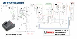
    Schemat Bosch GAL18V-20 Fast Charger.
    Electrical schematic of Bosch GAL18V-20 fast charger showing components and connections.

Topic summary

The discussion revolves around the repair of a Bosch AL1820CV Li-Ion charger that was damaged due to a faulty electrical connection. The user initially replaced a burnt resistor, capacitor, and fuse but encountered further issues, including a short circuit and burning components. Participants suggested checking the rectifier diodes, a TOP transistor (F3NK80Z), and other transistors like KT503 and 2N3904. The user confirmed the replacement of damaged parts and tested the circuit with a series bulb to limit current. After several measurements and replacements, the charger began to show signs of functionality, but questions remained about its compatibility with new high-current cells and the absence of over-discharge protection in the associated battery. The conversation included troubleshooting steps, component checks, and potential replacements for damaged parts.
Summary generated by the language model.
ADVERTISEMENT