logo elektroda
logo elektroda
X
logo elektroda

BOSCH AL 3640 CV - Short circuit after connecting the charger to the power suppl

daro19862 36726 43
ADVERTISEMENT
Treść została przetłumaczona polish » english Zobacz oryginalną wersję tematu
  • #1 13525362
    daro19862
    Level 25  
    Hello
    A friend gave me a broken charger with a battery.
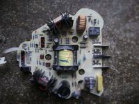
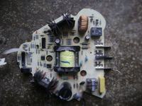
    After unscrewing it looks like this:
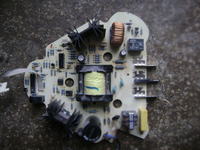
    BOSCH AL 3640 CV - Short circuit after connecting the charger to the power suppl

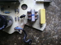
    I saw that the fuse is missing:
    BOSCH AL 3640 CV - Short circuit after connecting the charger to the power suppl

    I do not know what fuse was there, but in the manual I write something about BS 1363 / A and BS 1362 but I do not write for what current the fuse should be.
    I decided to bypass this fuse and see if the charger works, after bridging and connecting to the electricity the plug crashed.
    I measured the resistance on the power cable and there was no short circuit, the resistance is 0.5k Ohm.
    After looking at the board, I saw that there is a hole in the thermistor NTC 100-11:
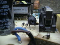
    BOSCH AL 3640 CV - Short circuit after connecting the charger to the power suppl

    I do not know when this hole in the thermistor was created, whether after bridging the fuse and connecting to the power supply, or if it was already there when I got the charger.

    I have a question:
    1) Does anyone know what current the fuse should be?
    2) Could this thermistor be the cause of a broken charger and should it work after replacement with a new charger?

    The charger is operational, I add a diagram of the primary part of the charger, it may be useful to someone:
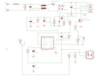
    BOSCH AL 3640 CV - Short circuit after connecting the charger to the power suppl
  • ADVERTISEMENT
  • Helpful post
    #2 13525560
    cezarjak
    Level 19  
    Hello.
    Thermistor 'evaporated' probably after bypassing the fuse or sooner. There is definitely a short circuit on or behind the bridge. Please check the diodes and whether there is a short circuit on the capacitor, then the driver and the transistor in the converter because it is definitely short-circuited. Please check if there is a short circuit after the thermistor on the diode bridge. What are the ICs there? Regards.
  • #3 13525738
    Marksrz
    Level 23  
    daro19862 wrote:
    Could this thermistor be the reason why the charger is not working and should the charger work after replacing it with a new one?

    Such a question means that you do not know what it is
    rather, you will not cope with yourself and the tips from the forum will not give you much, here you need to have some experience in repairing such power supplies
    The next short circuit you made definitely did more damage, don't try anymore
  • Helpful post
    #4 13525872
    filipski
    Level 17  
    The repair is simple.

    Remove the 4 1n4007 diodes, MOSFET transistor, NTC thermistor, fuse,
    Attach approx 16V power supply, - to n5 uc3845 a + to n7. In series with the power supply, a milliammeter should be about 20mA.
    Replace with new 4 1n4007 diodes, 8-10A and 600V MOSFET transistor, NTC 100 thermistor, 2A fuse.

    The repair cost is about PLN 10.
  • #5 13526183
    daro19862
    Level 25  
    cezarjak wrote:
    Hello.
    There is definitely a short circuit on or behind the bridge.


    Do you mean a rectifier bridge or some other?

    BOSCH AL 3640 CV - Short circuit after connecting the charger to the power suppl

    1) ST 1607502045
    2) ST LM324AN
    3) CNY17F-2
    4) UC3842B? probably because it is impossible to read.
    5) P6NK90Z I only saw that it is broken in half, there is 1.8 Ohm between the gate and the drain. It is located in front of the primary winding of the transformer marked 7 in Fig.
    6) STTH2003CT between leg 1 (A1) and leg 3 (A2) is 0.6 Ohm, these 2 legs go thick paths to transformer fig.7 for secondary output.

    I also noticed that 2 diodes from the rectifier bridge have a short circuit.

    So thermistor, rectifier diodes to be replaced, and how is it with P6NK90Z, I guess it's also broken and STTH2003CT?

    filipski wrote:
    The repair is simple.

    Remove the 4 1n4007 diodes, MOSFET transistor, ntc thermistor, fuse,
    Attach approx 16V power supply, - to n5 uc3845 a + to n7. In series with the power supply, a milliammeter should be about 20mA.
    Replace with new 4 1n4007 diodes, 8-10A and 600V MOSFET transistor, NTC 100 thermistor, 2A fuse.

    The repair cost is about PLN 10.


    After these measurements, what I have done, should I do as you write?
    All the elements that I checked were not desoldered from the board.
  • #6 13526518
    cezarjak
    Level 19  
    The rectifier bridge is these 4 diodes, it is best to replace all of the transistors for measurement, better to desolder p6nk90z, i.e. replace the mosfet because it is definitely damaged, it is not known uc3845 you need to check if there is no short circuit between the leg 7 and the leg 5. How will your colleague run the converters, I suggest connecting through a light bulb avoid burning, please read about it here on Electrode how to repair inverters, and take special precautions.
  • #7 13532952
    daro19862
    Level 25  
    I asked in the electronics store about the NTC 100-11 thermistor, the man from the store asked for the value in ohms, does anyone know what this value is?
  • ADVERTISEMENT
  • #8 13535519
    daro19862
    Level 25  
    Can I measure the resistance of an old thermistor and should I buy one?
  • #9 13536615
    filipski
    Level 17  
    Transistor, 4 diodes, fuse and thermistor replaced. I put on NTC 15D-15 because they were in the store :) Protection thermistor 15-30 Ohm diameter 10-15mm. this item is not critical. Watch out for soldering because the tracks tend to come off the laminate.
    Good luck.
  • #10 13543205
    daro19862
    Level 25  
    I replaced the transistor as it was, the original diodes that were inserted, the RL207, instead of them I put 4x FR206, instead of NTC 100-11 I put NTC 15D-15 15 Ohm, fuse 3A.
    And now I do not know if I should desolder STTH2003CT to check it, between leg 1 and leg 3 is 0.1 Ohm, these two legs go to the secondary winding of transformer No. 7, I do not know if it is normal that the resistance is so low.

    I am a bit afraid to connect to the network immediately so that nothing burns out again, can you write something more about connecting via a light bulb to avoid burning? I searched the forum but I can't find something.
  • ADVERTISEMENT
  • #11 13543676
    cezarjak
    Level 19  
    The bulb is connected in series with the power supply input, e.g. 60W to 230V, only ordinary, non-energy-saving and it consists in the fact that if there is a short circuit, the bulb will light up and will not damage the elements again, and when working properly it should only flash and go out because the inverter is not loaded with load. It is important not to load the inverter on the secondary side when connected through a light bulb, because it may be damaged. After taking measurements, we can disconnect the light bulb and test it under load. Regards.
  • #12 13546286
    daro19862
    Level 25  
    I replaced the diodes, the thermistor fuse and the transistor, after connecting to the electricity, the charger does not work. Transistor passes no current, no power on legs 5 and 7 of UC3842B.
  • #13 13547694
    cezarjak
    Level 19  
    In that case, what is the voltage on the main capacitor, it should be over 300V DC, please check the resistors and diodes supplying the system from the auxiliary winding, as well as the starting resistor, and check the system itself, maybe there is a zener diode in the circuit which is sticking, possibly a damaged resistor from measuring the current on the 3rd leg, what is its value, is connected between the transistor and ground as there was a short circuit, it could also be damaged.
  • #14 13547806
    daro19862
    Level 25  
    There is over 300V DC on the main capacitor.
    BOSCH AL 3640 CV - Short circuit after connecting the charger to the power suppl
    The resistor marked with 1 in the picture should power the UC3842B, before it is over 300V and behind it is already 0V, the resistance on the UC3842B power supply is 54 Ohm.
    The diode at UC3842B marked as 2 in the photo has a resistance of 67 Ohm, I checked in both directions without desoldering. The diode marked as 3 in the photo has a resistance of 54 Ohm one way.
  • #15 13547891
    cezarjak
    Level 19  
    I propose to raise at least one leg of the LEDs and then measure, or best to desolder the system and measure. I propose to measure this resistor and others by lifting at least one leg. Please check the optocoupler, it might also be damaged with such a short circuit. Unfortunately, unnecessarily, a colleague connected it without a fuse a second time and now these are the consequences, but we are only people and sometimes we will make a mistake.
  • #16 13548090
    daro19862
    Level 25  
    I desoldered the resistor No. 1 from the photo:
    BOSCH AL 3640 CV - Short circuit after connecting the charger to the power suppl
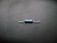
    Bar code: red, white and the latter, I do not know if yellow or green, if yellow, it should have 290k Ohm, if green is 2.9 Mohm, measure it with a 2M ohm meter and it closes the meter, I do not know how many Ohm it has.
    I desoldered the diode No. 2 and 3 from the photo, they have about 2 k Ohm in one direction, after desoldering these parts, there is still 54 Ohm in the UC3842B power line.
    Without a fuse, I only connected 1 time at the very beginning.
  • #17 13549664
    daro19862
    Level 25  
    I desoldered UC3842B and there is already high resistance on the power line of this IC. There is a resistance of 54 Ohm on the power supply legs of the IC, does that mean that the UC3842B needs to be replaced? How can it be instead of its UC3845 or some other replacement because I do not know if they will have such a part in my electronics store.
    As for the optocoupler, is there any way to check it?
    There is no short circuit on the 1st and 2nd legs as well as on the 4th and 5th legs.
  • #18 13550767
    cezarjak
    Level 19  
    As for the resistor, it should probably have 290, at least this is the result of the datasheet of this scalak, as for the scaler, it is certainly to be replaced with the same, it is said that it can be replaced with UC3843, but I only read it and never did it, let my colleague measure it other resistors because they can also be damaged and replace the UC chip.
  • #19 13551048
    daro19862
    Level 25  
    I already have a new chip, but I don't know what to do with this resistor.
  • #20 13551299
    cezarjak
    Level 19  
    It can be soldered at most, the system will not start because it is a starting resistor.
  • #21 13552771
    daro19862
    Level 25  
    I put in this old resistor and the UC3842B power supply was 1V and I changed it to 390 Ohm (I did not have 280 ohms) and the power supply was 15V but the diode does not light in the charger and after inserting the battery it also does not work.
  • #22 13555361
    cezarjak
    Level 19  
    And the inverter started working?
    What voltage behind the diodes on the capacitors after the secondary?
    Was only a colleague measured the power supply of the system? I suggest you measure the voltages on the capacitors, if the inverter started, if not either a short circuit on the secondary side or something else stoned.
  • #23 13555629
    daro19862
    Level 25  
    I also have a problem with 2 resistors, the first goes from 1 leg of P6NK90Z (gate) to the 6th leg of UC3842B (output) through another 67 Ohm resistor has a barcode orange black black so it should be 30 Ohm and over 2M Ohm (the meter closes) Ohm I put 32 Ohm for him.
    The second resistor is from the auxiliary winding, it is yellow, purple and black, so it should be 47 Ohm and it has 4.7 Ohm I put in place of 47 Ohm. I replaced the starting resistor with 300 Ohm and after connecting to the power the fuse, transistor, UC3842B and resistor 32 burned Ohm. Is it normal that the resistance on the transformer from the secondary side as well as from the main and auxiliary side has a resistance of 0.1 Ohm?
  • #24 13557037
    daro19862
    Level 25  
    However, I think I misread this barcode from the resistors.
    The one from the auxiliary winding, however, should have 4.7 Ohm, not 47 Ohm, as I read these 5 stripes confused me.
    Now I'm trying to determine the rest of the resistors, namely the starting resistor and the resistor that goes to the gate of the transistor and looks like this:
    BOSCH AL 3640 CV - Short circuit after connecting the charger to the power suppl
  • ADVERTISEMENT
  • #25 13557604
    cezarjak
    Level 19  
    I see, if instead of 300, he put a colleague 300, but om no, the system had to go, probably the colleague did not connect through the bulb and therefore such losses, you need to calmly check the elements once again and whether there is a short circuit on the primary and secondary side and run through the bulb then the colleague will avoid such damage.
    As for the measurement of the impulse transformer, this is how the meter will indicate because it has a very small number of turns and a large cross-section.
  • #26 13557647
    daro19862
    Level 25  
    I wrote it wrong, I did not insert 300 ohms, as I wrote above, only 300K Ohm.
    Today I will replace UC3842B, P6NK90Z, CNY17F-2 diode at UC3842B and diode from auxiliary winding. I just don't know the value of the resistor in the photo above and the starting resistor.
  • #27 13557701
    cezarjak
    Level 19  
    The resistor in the picture above is 1 ohm, the starting one will be rather 290 kom or if it is a brown first strip is 190 kom. I am giving a link to the datasheet, this is an example diagram, anyway, please enter the name of the system in google and press to show the graphics and the diagrams will pop up, you can use them. Good luck.

    http://www.onsemi.com/pub_link/Collateral/UC3842B-D.PDF
  • #28 13557886
    TONI_2003
    Moderator
    cezarjak wrote:
    The resistor in the photo above is 1 ohm

    You are wrong if the first strip is brown, the resistor value is 10 ? / 5% tolerance ...
    BOSCH AL 3640 CV - Short circuit after connecting the charger to the power suppl
  • #29 13558095
    cezarjak
    Level 19  
    Indeed, Toni 2003 is ourpartly vigilant and noticed my oversight, bronze -1 black-0 multiplier -0
    So actually 10 ohms, sorry for the mistake and thank you to Toni 2003 for noticing my mistake.
  • #30 13559752
    daro19862
    Level 25  
    I don't know the starting resistor anymore:
    BOSCH AL 3640 CV - Short circuit after connecting the charger to the power suppl
    It is next to the 10k Ohm resistor which has stripes: brown, black, black, red, bronze
    and the latter brown strip looks almost identical to the first strip of the starting resistor, while the third strip of the starting resistor looks green. So either 190k Ohm or 1.9M Ohm?

    The second resistor goes from the transistor's gate to the leg output UC3842B:
    BOSCH AL 3640 CV - Short circuit after connecting the charger to the power suppl
    It lies next to the resistor which has a value of 1.37k ohms and has stripes: Brown, orange, purple brown, green, the second strip, i.e. orange, is almost identical to the first strip of the resistor that goes to the gate of the transistor.
    Is it really 10 Ohm and not 30 Ohm?

    In the electronics store, they did not have CNY17F-2, only CNY17-3, I see that they differ a bit in the datasheet, can I solder the CNY17-3 to the charger?

Topic summary

The discussion revolves around troubleshooting a BOSCH AL 3640 CV charger that experienced a short circuit after a user attempted to bypass a missing fuse. The user discovered a damaged thermistor (NTC 100-11) and several other components, including diodes and a MOSFET transistor, which were also found to be faulty. Various responses provided guidance on testing and replacing components, including the use of a light bulb to prevent further damage during testing. The user successfully replaced several parts, including the UC3842B chip, and adjusted resistor values to restore functionality. Ultimately, the charger began to operate correctly, indicated by a blinking LED during battery charging and a steady light when fully charged.
Summary generated by the language model.
ADVERTISEMENT